Advanced Sheet Metal Design Using NX Cad Challenge_2_Box Assembly
PROJECT: Advanced sheet metal design using Siemens NX CAD - Box assembly.
OBJECTIVE: To design a box assembly and create a draft of it using the Siemens NX Sheet metal application.
INTRODUCTION: Sheet metal is formed by an industrial process into thin, flat pieces. Sheet metal is one of the fundamental forms used in metalworking, and it can be cut and bent into various shapes. Countless everyday objects are fabricated from sheet metal. Thicknesses can vary significantly; extremely thin sheets are considered foil or leaf, and pieces thicker than 6 mm (0.25 in) are considered plate steel.
DESIGN METHODOLOGY: The design methodology is explained by the flow chart as follows:
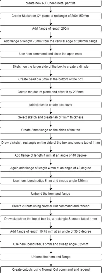
DESCRIPTION:
Sketch: It is the basic of any design.
Tab: It is used to create a base feature of sheet metal by extruding a sketch along a vector by a thickness value. Here tabs were created as the base of the top and bottom hinges as well as the base of the box.
Flange: It is used to create an extended part (bend) of a sheet metal. There are a total of twelve flanges created in the box assembly.
Unbend: This feature is used to unbend the adjacent bends and flatten them. Here it is used to create cutouts for the hinges.
Rebend: It is used to rebend the corners that were bent before along with any features added after the unbend feature.
Dimple: It lifts an area of the model inside a sketch that simulates a stamping tool. Here three dimples are created,i.e., in the middle of the base and two at the sides of the box.
Bead: It lifts material along the contour of a sketch that simulates a stamping tool, it is used for giving strength to the sheet metal. There are a total of four beads created around the dimple at the base.
Normal Cutout: It cuts the material by projecting a sketch onto the model and then cutting perpendicular to the faces intersected by the projection. Here a rectangular-shaped cutout was created to create the top and bottom hinges.
Mirror Feature: It copies a feature and mirrors it across a plane. Here the dimple on the side wall and beads on the bottom of the tab are created using this feature.
Hem Flange: It modifies the model by folding the edge of a sheet metal flange over onto itself for safe handling or to increase edge stiffness. It is used to create flanges on the walls of the box, on the sides of the lid, and also on the hinges.
Break Corner: It rounds or chamfers a sharp corner of a tab or flange. It is used in the tab created for the hinge.
Closed Corner: It closes a corner where two adjacent flanges meet by extending the bends and flanges. It is used to close the gap between the flanges used to create the walls of the box.
Mirror Body: It copies a body and mirrors it across a plane. The box, lid, and hinges are mirrored as a body using this command.
Unite: It combines the volume of two or more bodies into a single body. Two box and lid parts are combined using this feature to create a single body.
Flat Pattern: It creates a flat pattern feature from the formed sheet metal part. Separate flat patterns are created for the box, lid, and hinges.
Datum Plane: It creates a datum plane used to construct other features. It is created to form the lid.
Datum Coordinate System: It creates a datum coordinate system used to construct other features. It is created as a reference to mirror the bodies and the features.
IMAGES:
FRONT VIEW:
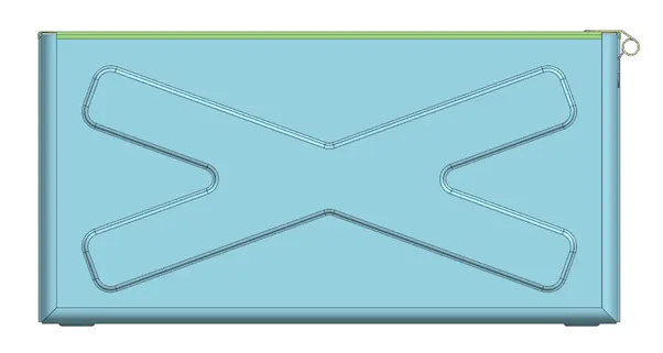
Back View:
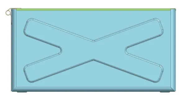
TOP VIEW:
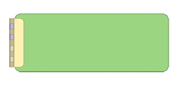
BOTTOM VIEW:
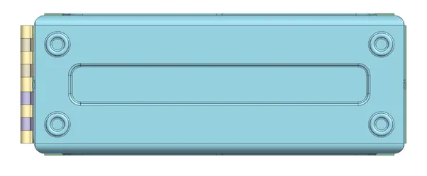
SIDE VIEW:
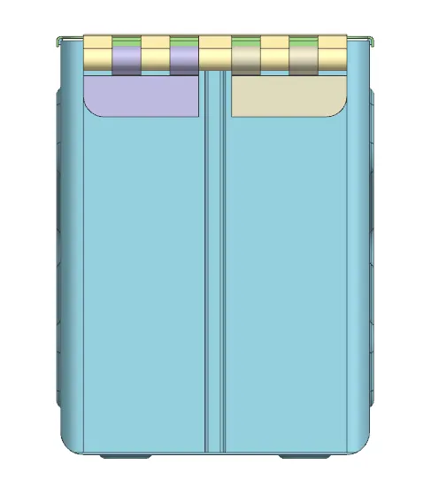
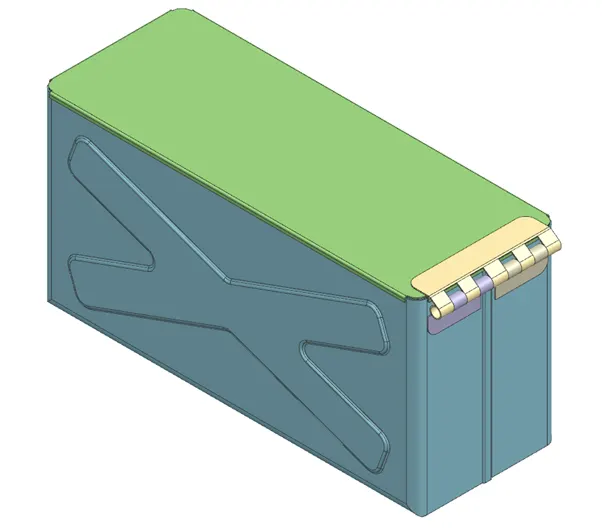
ISOMETRIC VIEW:
Conclusion: By performing this task, I have learned how to use features like tab, flange, break corner, closed corner, dimple, hem flange, bead, rebend, datum plane, datum coordinate system (Datum CSYS), flat pattern, mirror feature, mirror body, unite, normal cutout and unbend by creating a box assembly.