Advanced Sheet Metal Design Using NX Cad Challenge_2_Box Assembly
Advanced Sheet Metal Design Using NX Cad Challenge_2_Box Assembly
Objective: To Create a Sheet metal box
Introduction
Sheet Metal Fabrication is the process of forming parts from a metal sheet by punching, cutting, stamping, and bending. 3D CAD files are converted into machine code, which controls a machine to precisely cut and form the sheets into the final part.creating parts in sheetmetal cads can help to identify if the sheet can actuly be produceble from single punch,or in a single sheet.
Application of sheet metal designing can be small structures like supports, or products like small boxs, to large as aircraft ,cars,ISS etc.
Design methodology / approach (To be explained with the help of Flowcharts only)
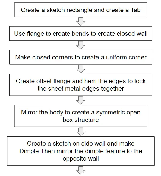
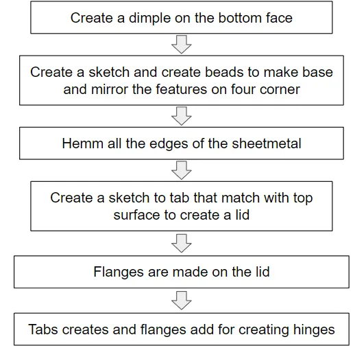
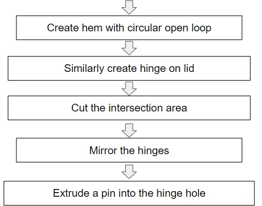
Description (Need to explain tools/ Features used while designing)
Tab: Tab is a tool used to create a base and the material properties sush as thickness bend radius to be followed to that sheet metal operation
Flange: Flange is a tool used to create bend sheet metal and extend
Closed corner: used to create a close walls where adjesent exted walls meet.
Dimple: a tool that creates closed sketches to stamped like projection,to increase strengths ,support or asthetics.
Unite: a comand used to combine bodies to singlebody
Bead: Convert sletches ,curves /line to stamped surface ,here we used to create a base stand
Hemm: Used to bend edges of sheetmetal to strengthen,avoid sharp edges, or to join sheetmetals
Mirror body: usesd to mirror selected body with respect to a plane
Normal cutout: Used to remove material with respect to the sketch drawn
Break corner: round and chamfers the corner.
Unbend: an operation used to unbend and flaten a bend surface to do some operation on the bend
Rebend: rebend is used to bend back the thend flage surface
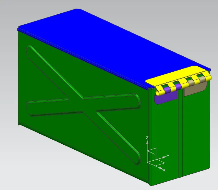
Top view
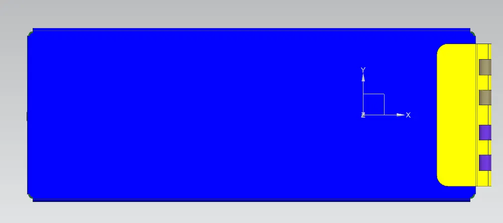
Bottom view
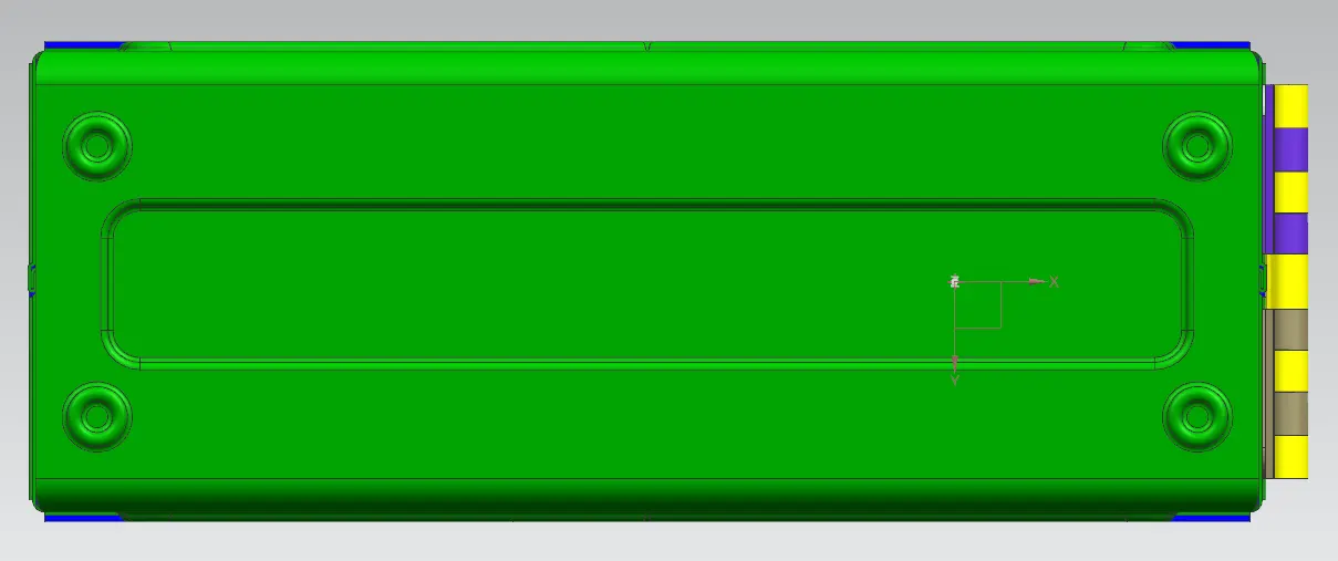
Side view
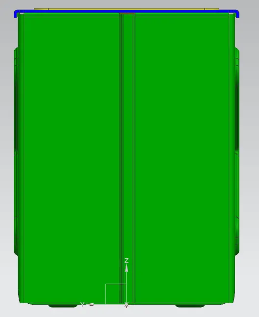
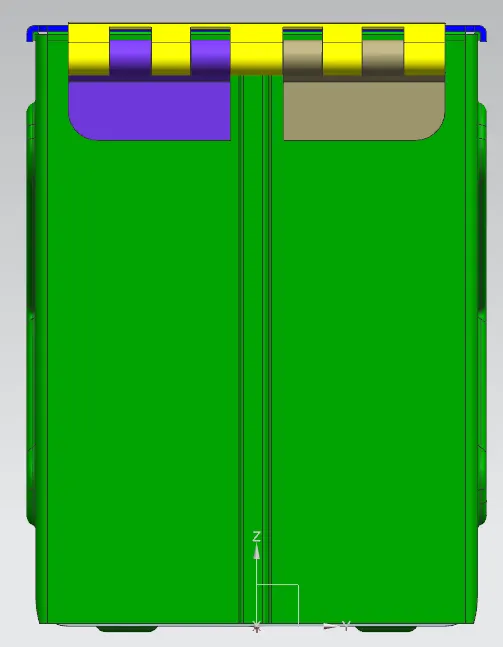
Conclusion
Box assy was done on nx12 and results seem satisfactory