Advanced Sheet Metal Design Using NX Cad Challenge_2_Box Assembly
ADVANCED SHEETMETAL DESIGN OF BOX ASSEMBLY USING NX CAD
OBJECTIVE: To create a box assembly using various tools available in NXCAD
INTRODUCTION: Sheet metal parts are widely used in machinery, enclosure, brackets, and automobile due to its various advantages. The parts are normally manufactured with break press. Sheet metal is nothing but the thin sheets made from metal of size ranging from 0.5 to 6mm. In this project I used NX CAD tool for designing the sheet metal bracket. NX CAD is used as design tool in more than 85% of the sheet metal industries.
DESIGN METHADOLOGY AND FEATURES USED WHILE CREATING
1. Tab
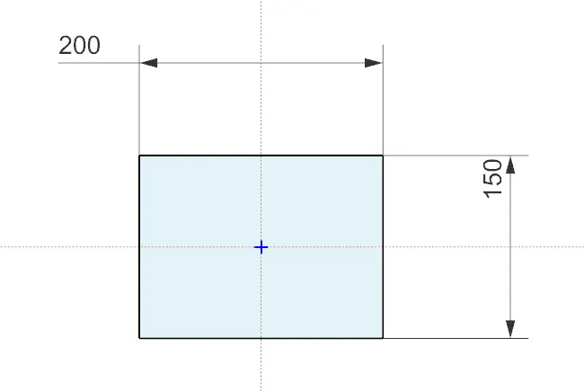
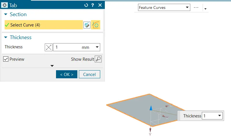
Tab is the first parent feature in sheet metal designing using Siemens NX tool. All the other feature are usually based on tab.
2. Flange
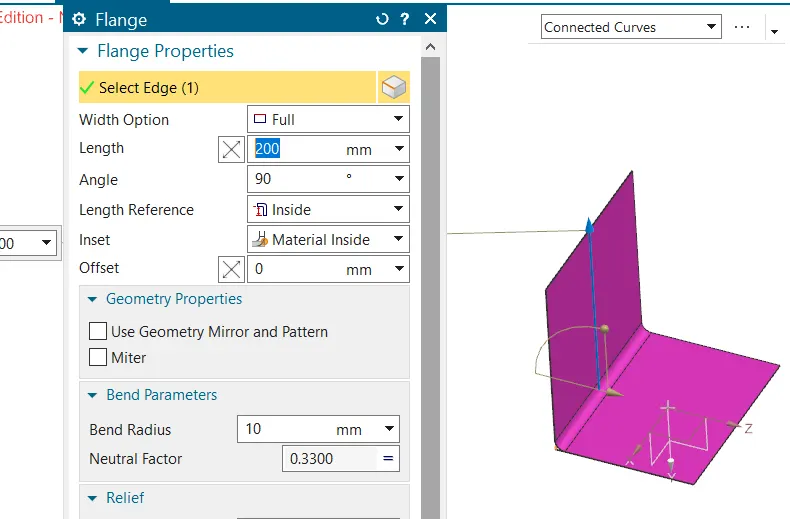
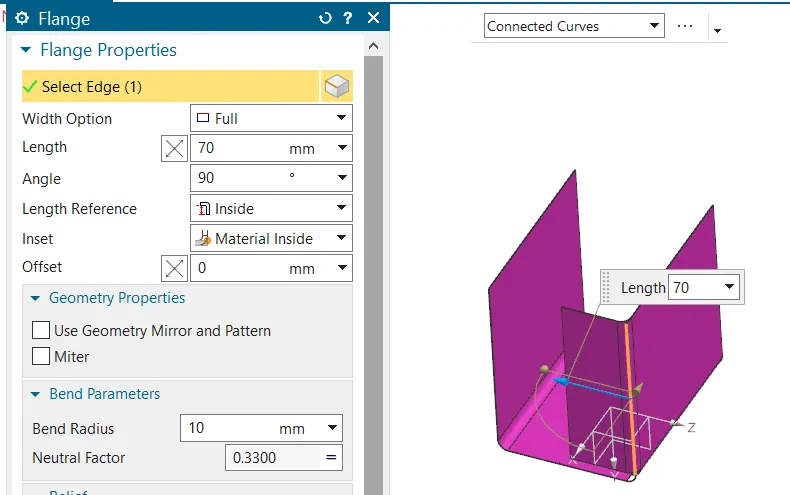
Flange is used to add extra material to the existing edge at any angle and of any size. For this project of box assembly design, I added four flanges on different edges, firstly I added two flanges with 200 mm length normal to the XY plane and then another two flanges with length of 70 mm were added normal to XZ plane.
3. Closed corner
Close corner feature is used to close a corner where two adjacent flanges meet by extending the bends and flanges. For this box assembly I used the closed corner feature twice to close the open corners at the bottom side of the flanges.
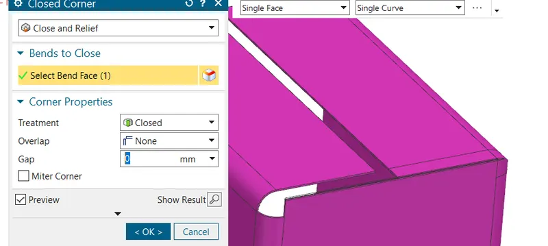
4. Flange for fastening
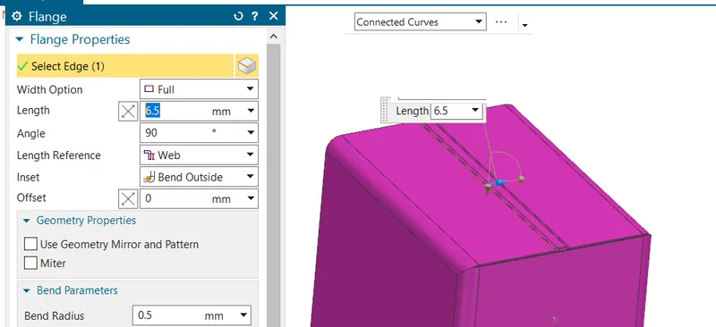
For fastening or connecting the two flanges on side of box assembly I first created a flange without length and then another flange having dimension of 6.5 mm length with outside bend.
5. Hem flange
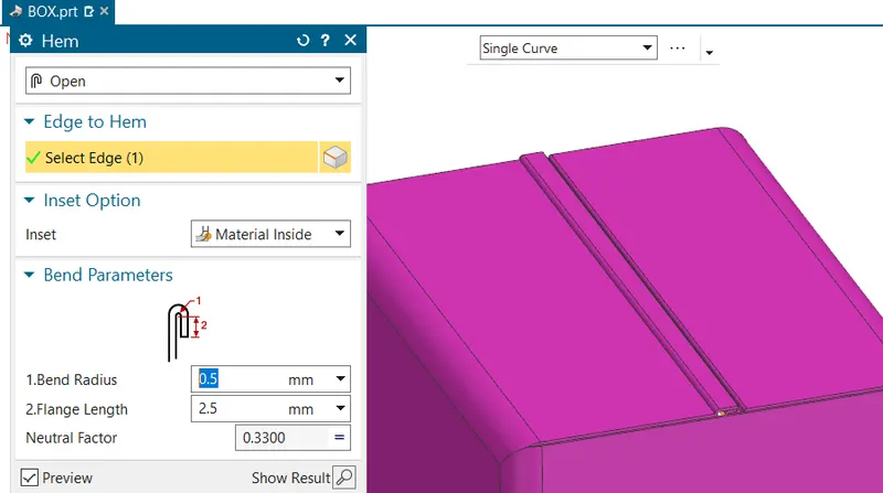
Hem flange feature is used to modify the model by folding the edge of a flange. The main purpose of this feature is to increase the stiffness and for safe handling.
6. Mirror body
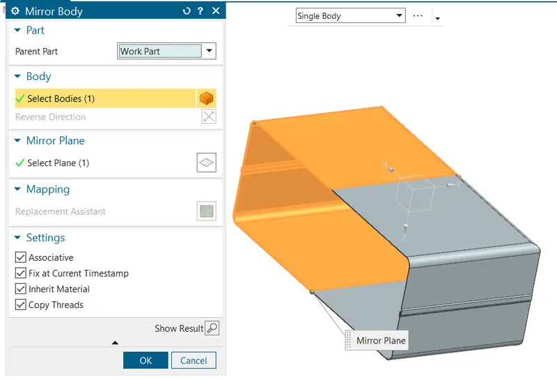
As of now half part of the box assembly was designed remaining half part was designed by using mirror body feature, which saves lot of time. I used to mirror body feature to mirror the half body about YZ plane.
7. Unite
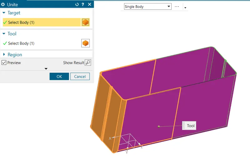
Unite feature is used to combine two different bodies which are in contact. I used unite feature to combine the body before the mirror and after the mirror feature.
8. Dimple
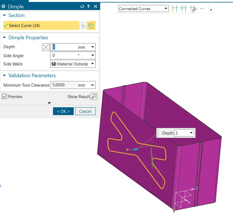
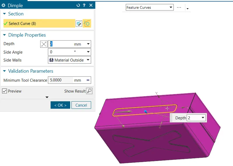
Dimple is the feature that lifts the area of model inside the sketch that simulates a stamping tool. Generally, it helps to strengthen the flat structure. For this box assembly I first created an appropriate sketch and then I used dimple feature to create the final dimple on one side of box assembly. Same dimple was mirrored to the other side of box. One rectangular dimple was also added at the bottom of the box assembly for the purpose of perfect landing.
9. Bead
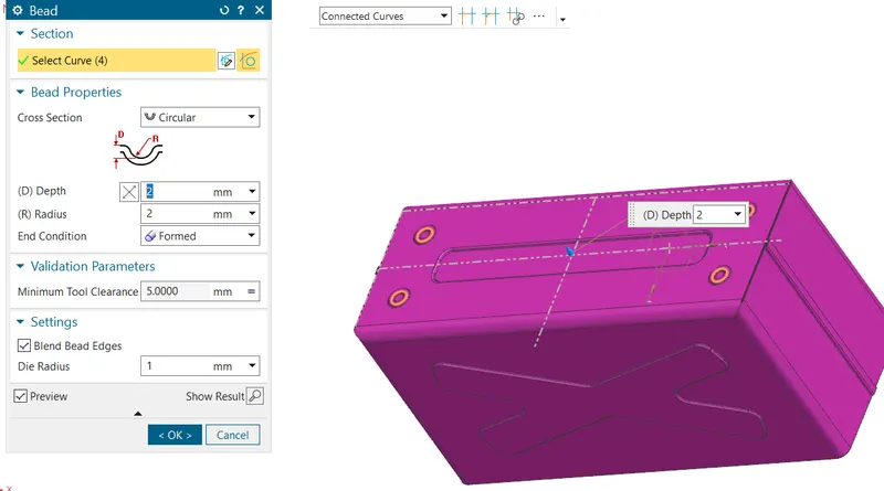
Beads are similar feature like dimple the only difference is that by using dimple we lift an area while in bead we lift the contour of the sketch. It also added to strengthen the component.
10. Hem flange
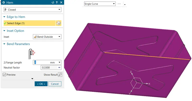
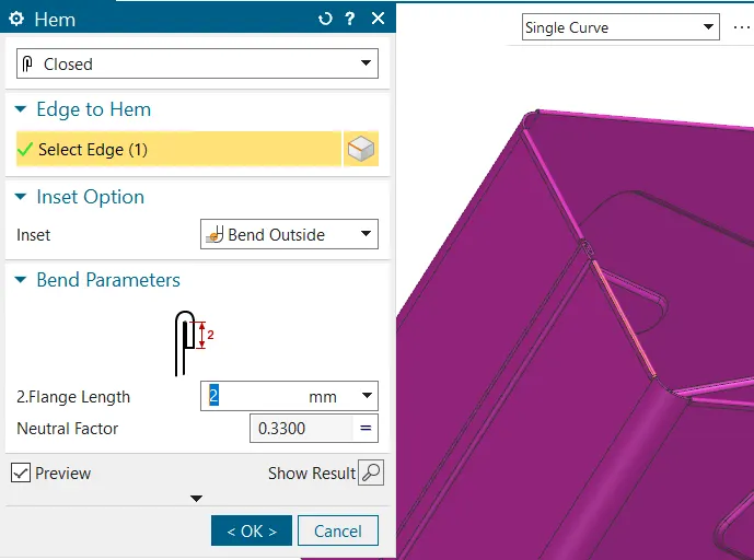
At this stage hem flange is used to create rounded edge at the top which helps in easy handling.
11. Lid creation
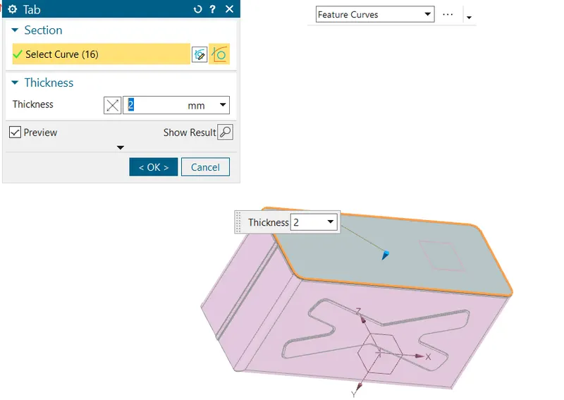
For creating the lid for the box, a datum plane was created at a distance of 202 mm from XY plane. The sketch was created by taking the reference of the edges from the top view of the box design. Then the base tab was created with the sketch to create the lid.
12. Flanges
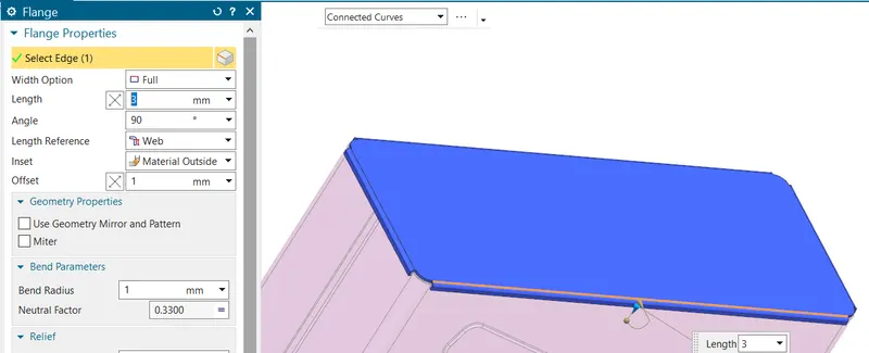
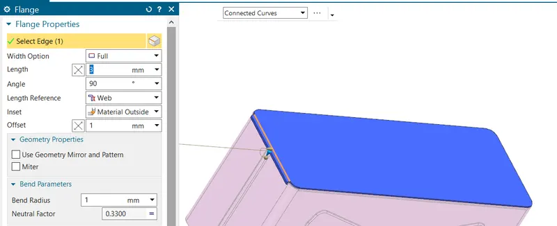
For closing box with proper alignment flanges having web length of 3 mm were added to both sides.
13. Tab for creation upper hinge
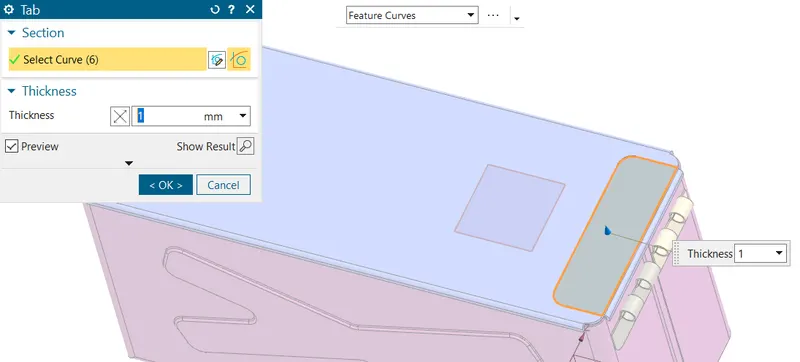
A single rectangular tab was created on top surface of the lead.
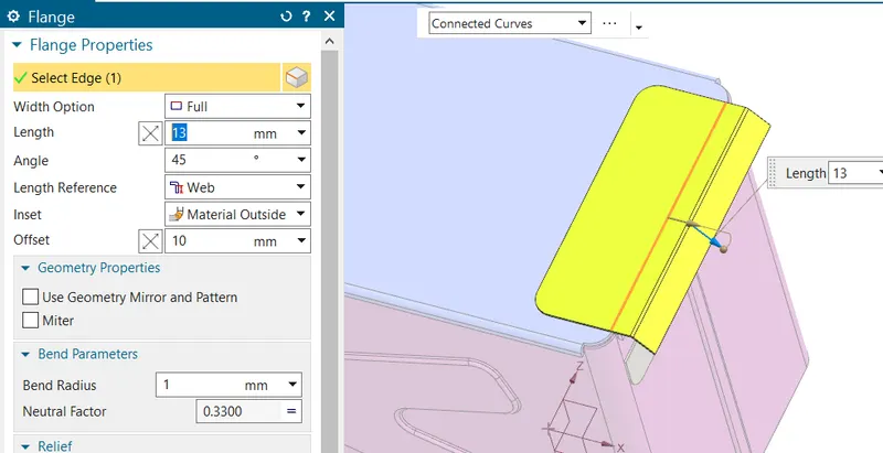
14. Flange
15. Hem flange
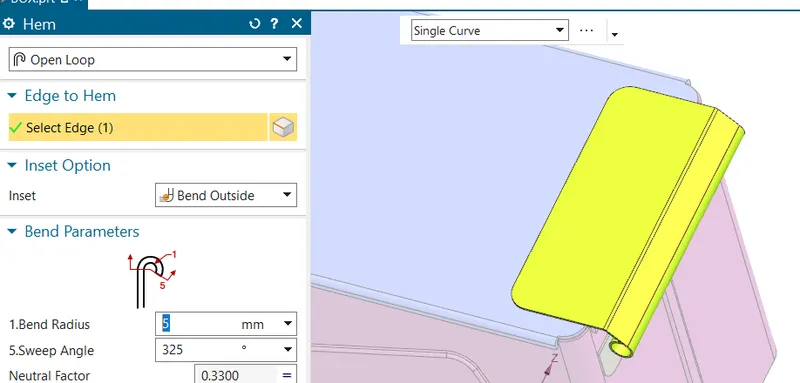
Similar to the earlier process, an open hem flange of radius 5 mm with angle of 325 degree was created.
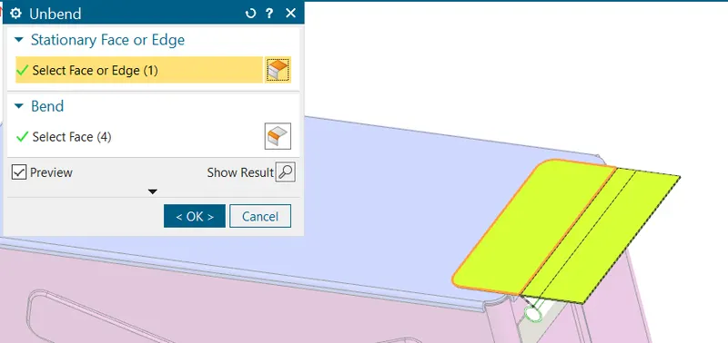
16. Unbend
Unbend the tab for creation of cutouts.
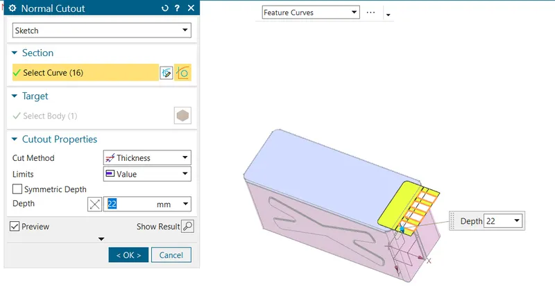
17. Normal cutout
As per the requirement material is removed in the form of four rectangles by using normal cutout feature for creating the hinge barrel.
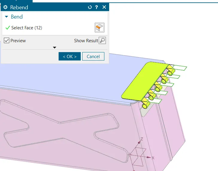
18. Rebend
Part of upper tab which was unbended for crating the hinge barrel was rebended and the design for box assembly completes.
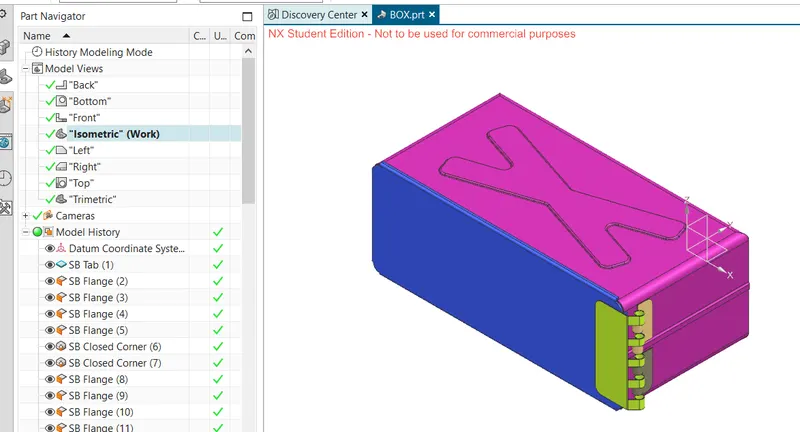
ORIENTATIONS OF BOX ASSEMBLY
Isometric view
Front view
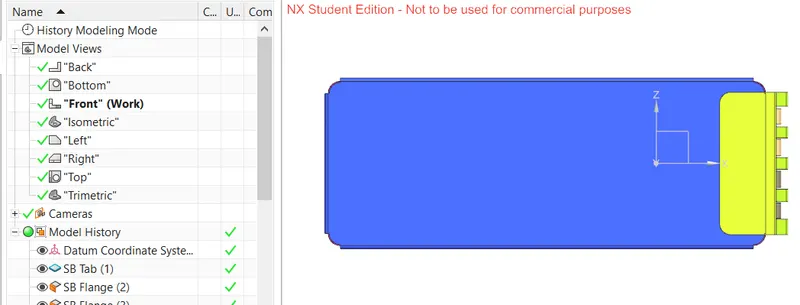
Top view
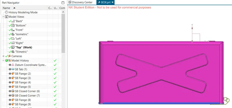
Side view
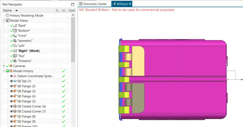
Drawing sheet
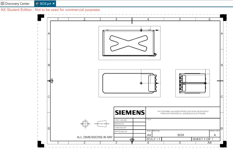
CONCLUSION: Thus we have successfully created BOX ASSEMBLY using NXCAD commands