Advanced Sheet Metal Design Using NX Cad Challenge_2_Box Assembly
DESIGN OF SHEET METAL BOX ASSEMBLY USING SIEMENS NX CAD
Objective
The aim of the project is to design the sheet metal box assembly (box with its features) by following the industrial design methodologies for manufacturing a sheet metal component.
Introduction
Sheet metal is any metal that has a thickness in between 0.4 to 6 mm and it can be obtained by any metal rolling process method (cold rolled and hot rolled). Sheet metal widely used in industries like automobile, aerospace, electronic appliance, medical, construction, furniture, etc. To utilize sheet metal to its full extent we must understand standard measurements, materials, differences in manufacturing, possible forming methods and the material properties.
Sheet metal fabrication is the process of forming metal sheets to the desired shape using different manufacturing methods. The completion of a product usually comprises of many steps – from cutting and bending to surface treatment and assembling.
Sheet metal box assembly design
Sheet metal box are mainly used for storage of sensitive equipment and thus protect it from external hazards. Here we are going to design the sheet metal box with a lid, hinge reinforcement and other supporting features by following the industrial standards and manufacturing process.
Design methodologies
- For designing any component the first step is to select the appropriate material which is exactly suitable for the component.
- Required size and thickness for the base body should be calculated and fixed.
- Calculating the dimensions of other features and freeze it.
- Finalizing the manufacturing process which is suitable for the component.
- Now the designer will start developing the component /part with reference to the input data.
- Here for the box design first we have to create the base sheet for the main body with reference to the input data.
- From the base sheet develop the main body of box by following step by step operation used for manufacturing process: like cutting, punching, drawing, bending, notching, etc.
- The lid for the box should be developed by suitable dimensions and positioned.
- Then additional features like hinge bracket, reinforcement, pin hinge provisions are developed and positioned with reference to the main body and lid of the box.
- All the sheet metal box components are developed by applying step by step operation used for manufacturing process: like cutting, punching, drawing, bending, notching, etc.
Steps followed
- Create the fully constraint sketch for the main body of sheet metal box by following the dimensions from the input data and set the sheet thickness and other parameters in the sheet metal preference tool bar.
- Convert the sketch into the base sheet by using tab operation with appropriate thickness.
- From the base sheet flanges are created on the four sides expect the center part with appropriate dimensions to form a box structure.
- Corners between the main sheet and the bottom surface of two small adjacent flanges are closed by using closed corner command.
- Additional flanges are added to create a hem joint between the adjacent flanges at smaller side.
- After applying the hem operation entire sheet metal body is mirrored to form a full box.
- Unite the mirror body with his parent body to from the required box.
- To increase the structure stability dimple are applied on the larger side of the box using a sketch and the same I mirrored to the opposite side.
- Another dimple is applied to the bottom surface of the box using a rectangular shaped sketch.
- Unbend and re-bend command is applied to validate the sheet metal.
- Bead is applied to the all four corners of the bottom surface by using a single sketch and mirror it on all other three corners.
- Now all the outer edges at the top side of the box are close hemmed.
- The second part of the box assembly will be the lid and this is designed by using a sketch on the plane which at an appropriate distance from the base sheet.
- Flanges are added to the edges of the lid to make it proper fit with the main body.
- The functional features (pin hinges) of the box and the lid will be developed by positioning the sketch on the appropriate place and create the base sheet using tab command.
- First create the sketches on the smaller side of the main body and apply tab command to form the base body
- Corner reliefs are applied to the required areas by using break corner command.
- Additional flanges are added with proper angle to make them open loop hems to get a cylindrical shape for the supporting bracket of the pin hinges.
- After applying hemming the sheet metal is un-bend for creating a sketch which is used for cutting the sheet metal and remove excess material gives a proper shape.
- Re-bend the material for getting the original shape.
- Now the feature is mirror to the adjacent side of the main body to form a single unit.
- From the top surface of lid another base sheet is develop by a sketch and added additional flange at an angle facing downwards.
- An open loop Hem is applied to the flange to get the proper shape.
- Unbend the feature and by using a sketch cut the unwanted sheet metal from the unbend sheet which should be match with the feature on the main body.
- Finally, the re-bend tool is applied to get the final product.
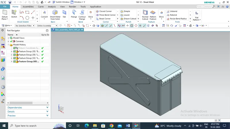
ISOMETRIC VIEW OF SHEET METAL BOX ASSEMBLY
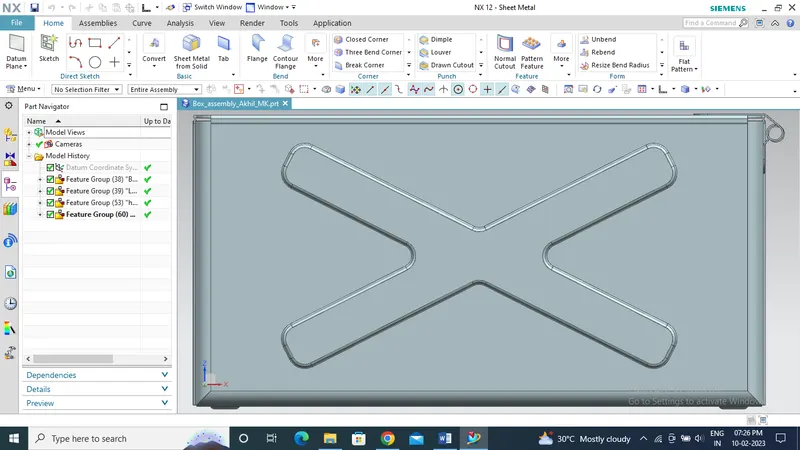
FRONT VIEW OF SHEET METAL BOX ASSEMBLY
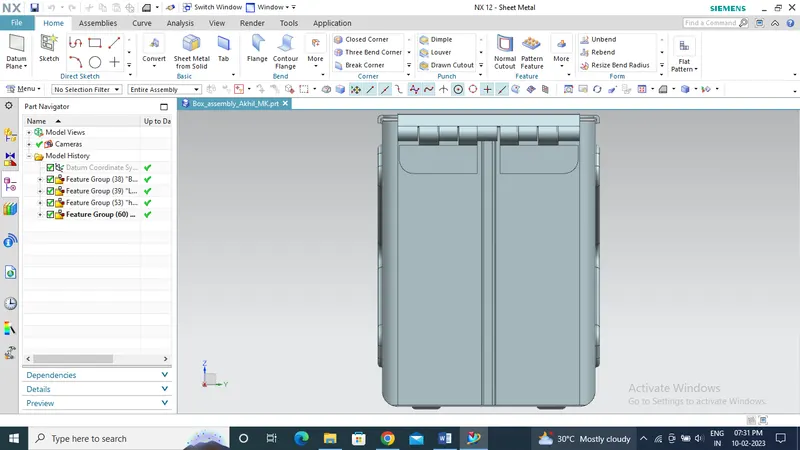
RIGHT SIDE VIEW OF SHEET METAL BOX ASSEMBLY
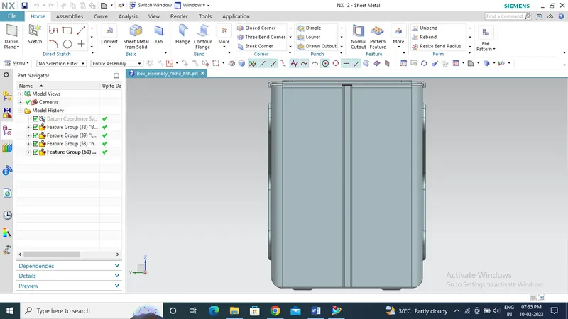
LEFT SIDE VIEW OF SHEET METAL BOX ASSEMBLY
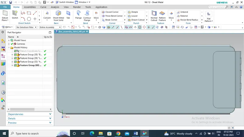
TOP VIEW OF SHEET METAL BOX ASSEMBLY
Conclusion
Sheet metal box, lid and its features was designed with the help of SIEMENS NX CAD by following the manufacturing process and input data.