Advanced Sheet Metal Design Using NX Cad Challenge_2_Box Assembly
BOS ASSEMBLY DESIGN
OBJECTIVES-
Create a Box assembly design model following the given guidelines by using NX Sheet metal application.
https://drive.google.com/open?id=1kjkKrjCXfoGbNzqP9lZ9ogPpNIswBoLR
INTRODUCTION-
Sheet metal parts are widely used in machinery, enclosure, brackets, and automobile due to its various advantages. The parts are normally manufactured with break press. Sheet metal is nothing but the thin sheets made from metal of size ranging from 0.5 to 6mm. In this project I used NX CAD tool for designing the sheet metal bracket. NX CAD is used as design tool in more than 85% of the sheet metal industries.
DESIGN METHODOLOGY-
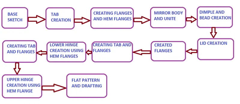
DESCRIPTION-
- SKETCH: This is used to create a basic sketch of the design on selecting the desired plane, then later it can be modelled for a requirement.
- TAB: This feature is used to create a base tab on selecting the curve drawn in sketch mode with the appropriate thickness on our desire and it can be easily converted that sketch into a sheet.
- FLANGE: Flange is used to add flanges on selecting the edges of our sheet, it works as a BEND feature along with that extra material can be added by adjusting the length of the flange.
- CLOSED CORNER: This feature is used to close the corners by selecting two flanges.
- HEM FLANGE: This feature is used for different purposes like stiffening and also for easy holding without making any physical hurts.
- DIMPLE: It is used to draw a dimple on selecting a curve for modelling the sheet.
- MIRROR BODY: This feature is used to create a copy of the body part in the opposite direction.
- BEND: This feature is used to bend the sheet metal along the sketched curve upon our requirement.
- BREAK CORNERS: Break corners is used to make the edges round for easy handling when using.
- NORMAL CUTOUT: This feature is used to cut the portions of the sheet metal by giving sketch curves.
- UNBEND: Unbend is a feature used to analyze the model whether it has perfectly assigned the alignments, which ensures for the modeler to do further operations on it.
- BEADS: This feature is used to create a bead on the sheet which generally strengthens it.
- REBEND: This is used to re-bend the object after all conformations.
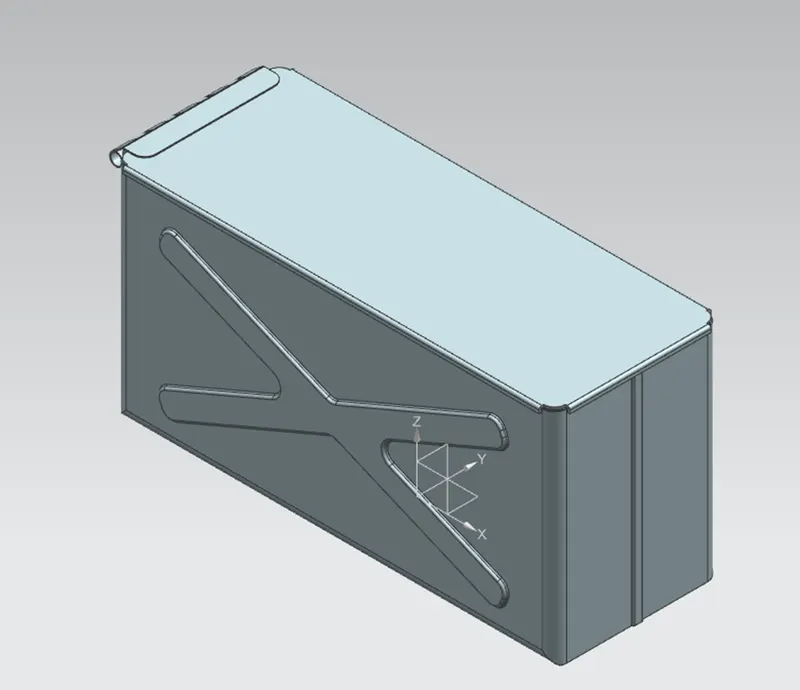
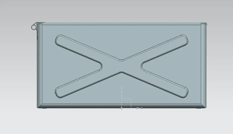
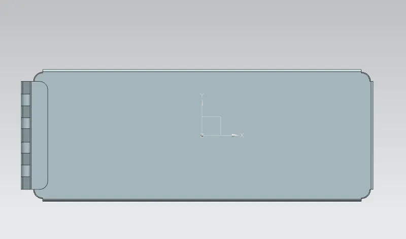
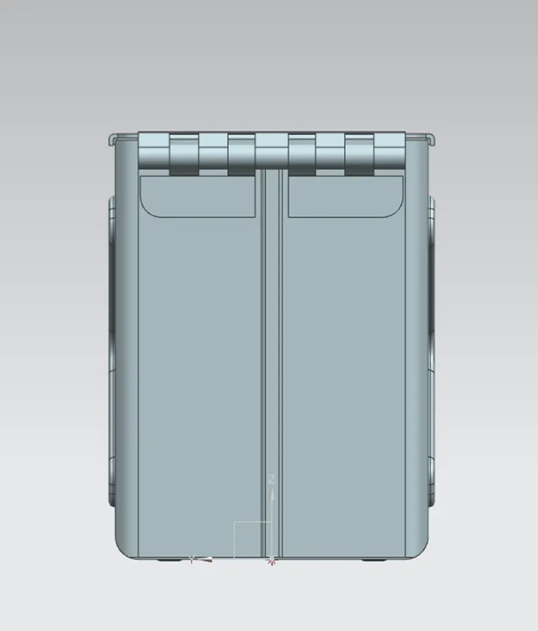
VARIOUS VIEWS OF MODEL-
- ISOMETRIC VIEW-
- FRONT VIEW-
- TOP VIEW-
- SIDE VIEW-
CONCLUSION-
In this challenge we created the sheet metal Box assembly model using given guidelines. We learn about the various commands in NX Sheet metal application.