Advanced Sheet Metal Design Using NX Cad Challenge_2_Box Assembly
Title: Box Assembly.
Objectives: To design a Box assembly using Siemens NX sheet metal application.
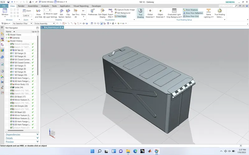
Introduction:
- NX is one of the world’s most advanced and tightly integrated CAD/CAM/CAE product development solutions. Spanning the entire range of product development, NX delivers immense value to enterprises of all sizes. It simplifies complex product designs, thus speeding up the process of introducing products to the market.
- The term “sheet metal” refers to any metal that can be formed into flat pieces of varying thicknesses. Thick metals are called plate. Metals used in the sheet metal industry include cold rolled steel, mild steel, stainless steel, tin, nickel, titanium, aluminum, brass, and copper.
- Base was created using Tab command.
- Walls were created using Flange command.
- Corners were closed using Close corner feature.
- Used Flange and Hem flange feature to lock the walls.
- Whole box was created using Mirror feature command.
- Unite the two bodies.
- Create a profile on the side walls.
- Created a Dimple using the previous profile.
- Using the mirror feature copied the dimple on the opposite side.
- Created a emboss on the base using dimple feature.
- Unbend and Rebend the box.
- Four beads were created on the base using Bead and Mirror feature.
- Created hem flange on the top of walls on all four sides.
- Box cover was created using tab command.
- Flange was created on one side of the box cover.
- Tab was used to create base for the hinge.
- Using flange, Hem flange normal cut out hinge was creation the side wall.
- Using mirror feature another hinge was created.
- Similarly another hinge was created on the box cover.
- Changed the colour of the box and cover.
Description:
STEP 1 (TAB): Using sketch create tab of desired shape and size.
STEP 2 (FLANGE): Create flanges on both sides of the tab with desired height.
STEP 3 (FLANGE): Close the above flange with another set of flanges over the existing once.
STEP 4 (CLOSED CORNER): Generate a comer between flanges using closed corner command.
STEP 5 (FLANGES): Provide extension to the flanges to lock each other,
STEP 6 (HEM FLANGE): Using hem command create bend outside the length of the flange to enable it to interlock with other flange.
STEP 7 (MIRROR BODY): By using Mirror body feature the existing arrangement is replicated on the opposite side just like a mirror.
STEP 8 (UNITE): Unite the two different arrangements as one using Unite feature.
STEP 9 (DIMPLE): Create dimple using sketch plane on the side of the box.
STEP 10 (MIRROR FEATURE): By using mirror feature command repeat the dimple on the other side of the box.
Step 11 (DIMPLE): This time create dimple at the base of the box.
STEP 12 (UNBEND AND REBEND): Unbend and rebend the entire design model to adjust the features according to their bends.
STEP 13 (BEADS AND MIRROR FEATURE): Create one bead using bead feature. Multiply the bead feature using mirror feature with reference point at its symmetry.
STEP 14 (HEM FLANGE): Smoothen the box edges by applying hem flange to it.
STEP 15 (TAB): Create new sketch plane and sketch the lid of the box. Use tab feature to give a sheet metal format to lid.
STEP 16 (FLANGES): Using flanges generate a interlock shape to the lid to fix it on to the box.
STEP 17 (TAB): Sketch the handle support on both lid and the box. Provide an extension to the lid for handle support.
STEP 18 (BREAK CORNER): Provide a curvature on the support created on the box by invoking Break Corner.
STEP 19 (FLANGES AND HEM FLANGE): By using suitable combination of flange and hem flange generate the shape of the handle on both lid and the box.
STEP 20 (NORMAL CUT OUT): Unbend the hem and by using Normal Cut-out command create a desired handle shape which will not interfere each other. Use sketch as a reference point for cut outs
STEP 21 (MIRROR BODY): Rebend the hem and apply Mirror body for two such handles.
Images:
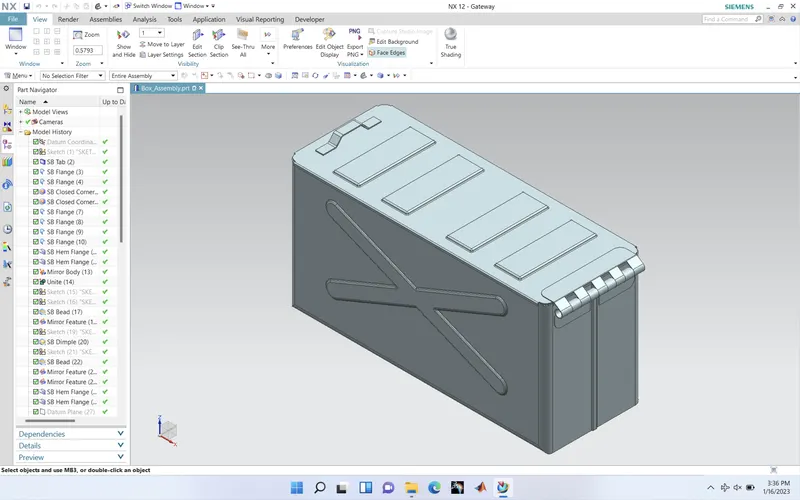
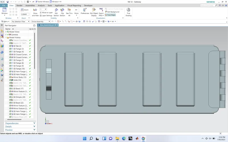
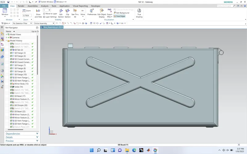
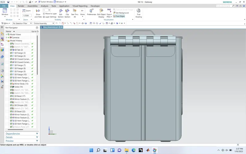
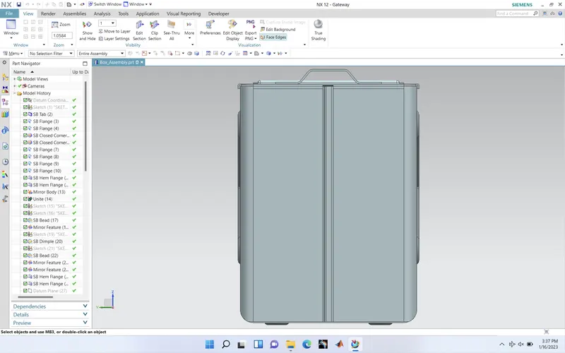
Conclusion:
In this report we have analysed a detailed stepwise approach of design sheet metal Box Assembly and established path procedure in creating features at desired locations with suitable parameters.