Advanced Sheet Metal Design Using NX Cad Challenge_2_Box Assembly
TITLE: BOX ASSEMBLY
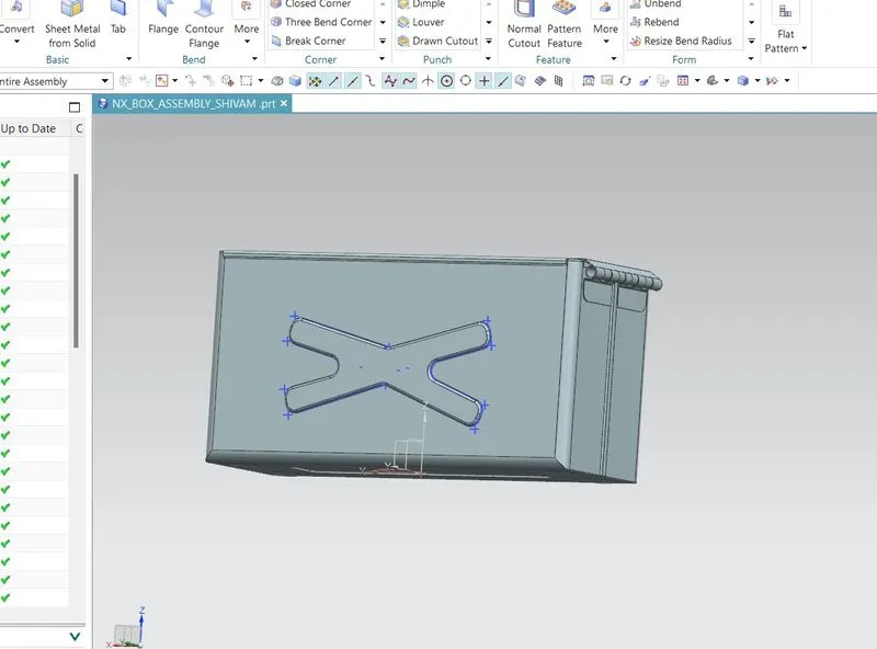
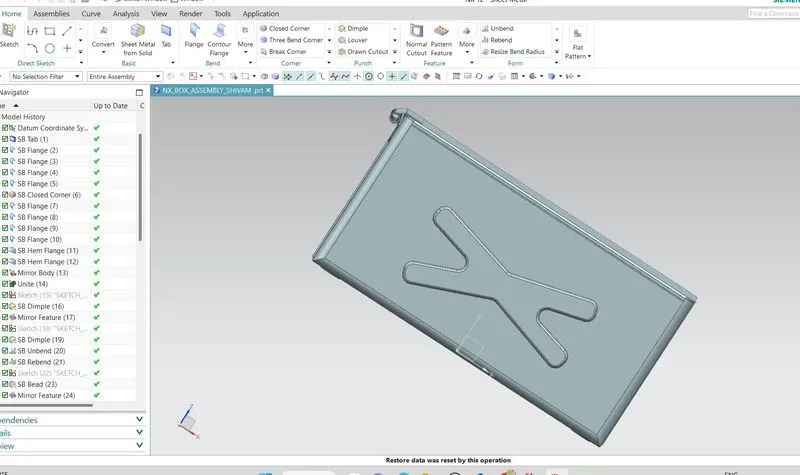
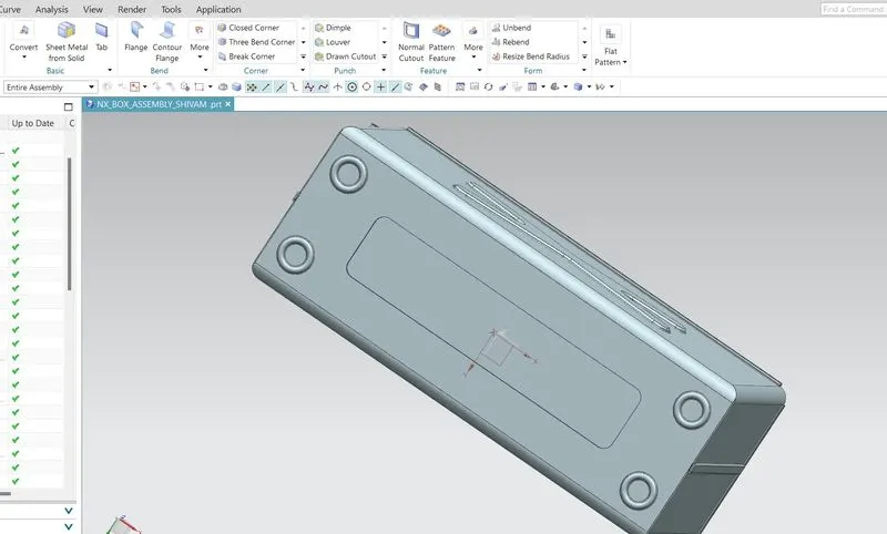
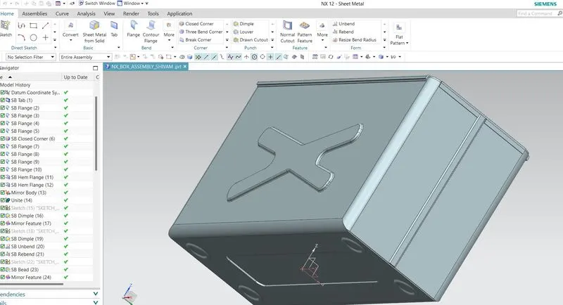
OBJECTIVE: To design a sheet metal model of BOX ASSEMBLY by using Siemens NX CAD tool.
INTRODUCTION:
Sheet metal fabrication is a non-additive, non-subtractive process. It begins with flat material and, by definition, maintains constant material thickness throughout apart. In some cases, areas of a part can be selectively thickened by welding multiple metal sheets together, but this is a costly and uncommon practice.
Designing for sheet-metal fabrication has its own criteria, which differ from those of other production processes. The more that’s known early in the design phases about a part’s features and functions, the sooner a manufacturable design will finalized. If, however, a design has problematic features, a manufacturing supplier should be able to point those out and suggest ways of addressing them. In some cases, the supplier may even have design analysis software that can quickly highlight issues for design improvement. Some design consideration:
- Sheet metal fabrication is most economical when it uses configurations of “universal” tools rather than part-specific tooling. If a single part becomes too complex, consider welding or riveting together parts that can be made using universal tools.
- Because bends stretch the metal, features must stand away from bends to avoid distortion. A useful convention is 4T—four times the material thickness.
- A press brake creates a bend by pressing sheet metal into a die with a linear punch, so the design does not allow the creation of closed geometry.
- Sheet metal tolerances are far more generous than machining or 3D printing tolerances. Factors affecting tolerances include material thickness, machines used, and a number of steps in part production. Suppliers will typically provide detailed information on tolerances.
- A uniform bend radius such as 0.030 in. (industry standard) should be used across a single part to reduce the number of machine setups and accelerate production.
- Where possible, maintain a standard distance of four times the material thickness from bend to edge. This will eliminate the need to remove excess material required to make the bend.
- Welding thin materials can lead to cracking or warping. Other assembly methods are preferable.
There are some of the design tool software are available like CATIA, AUTOCAD, NX CAD, SOLID WORKS, PROE, etc. I have chosen the NX CAD of SIEMENS to design this CASING part.
DESCRIPTION:
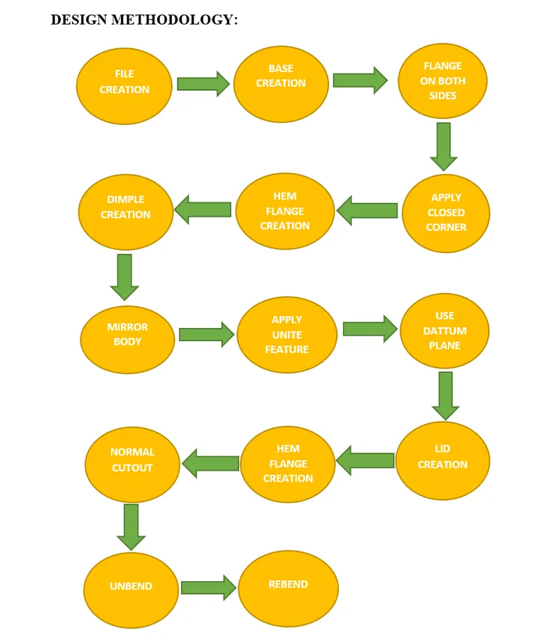
FEATURES USED:
- SKETCH: This is used to create a basic sketch of the design on selecting the desired plane, then later it can be modeled for a requirement.
- TAB: This feature is used to create a base tab on selecting the curve drawn in sketch mode with the appropriate thickness on our desire and it can be easily converted that sketch into a sheet.
- FLANGE: Flange is used to add flanges on selecting the edges of our sheet, it works as a BEND feature along with that extra material can be added by adjusting the length of the flange.
- CLOSED CORNER: This feature is used to close the corners by selecting two flanges.
- HEM FLANGE: This feature is used for different purposes like stiffening and also for easy holding without making any physical hurts.
- DIMPLE: It is used to draw a dimple on selecting a curve for modeling the sheet.
- MIRROR BODY: This feature is used to create a copy of the body part in the opposite direction.
- BEND: This feature is used to bend the sheet metal along the sketched curve upon our requirement.
- BREAK CORNERS: Break corners is used to make the edges round for easy handling when using.
- NORMAL CUTOUT: This feature is used to cut the portions of the sheet metal by giving sketch curves.
- UNBEND: Unbend is a feature used to analyze the model whether it has perfectly assigned the alignments, which ensures for the modeler to do further operations on it.
- BEADS: This feature is used to create a bead on the sheet which generally strengthens it.
- REBEND: This is used to re-bend the object after all conformations.
RESULTS OF BOX ASSEMBLY DESIGN: