Advanced Sheet Metal Design Using NX Cad Challenge_2_Box Assembly
Advanced Sheet Metal Design for Box Assembly In NX CAD
Objective: To design the sheet metal Box assembly using NX CAD and understand how to use the different sheet metal design elements needed to make the sheet metal components based on industrial purpose.
Introduction: "Sheet metal" refers to any metal that may be formed into flat pieces of various thicknesses. Thick metals are referred to as plates. The sheet metal industry uses a variety of metals, including cold-rolled steel, mild steel, stainless steel, tin, nickel, titanium, aluminium, brass, and copper. To design the sheet metals, we employ programmes like Creo, NX, Catia, etc. Depending on the product and manufacturing method, straight brake sheet metal forming is the most common. NX Within the NX design environment, Sheet Metal provides a collection of tools that make it simple and rapid to design sheet metal components. The advanced characteristics of NX can be utilised to design box assembly, one of the sheet metal components needed to encase or protect the inside sections.
Design methodology:
The following processes are carried out in order to create a sheet metal component.
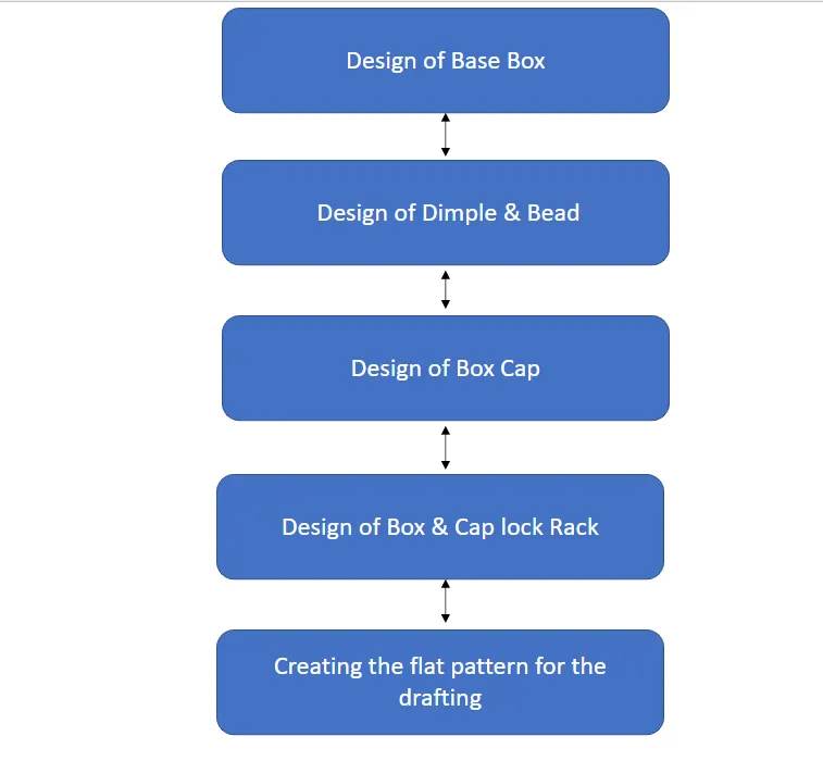
Description:
The following features are used to complete the box assembly design in order to design the box assembly.
Step 1: Creating bottom tab with flanges on each side.
Tools Used:
Sketch: Sketch generates a 2D visual for the model when there are many sketch commands present, such as lines, rectangles, circles, etc.
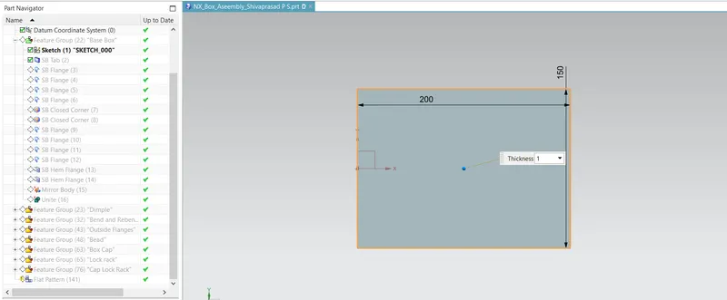
Tab: Tab creates a Base Extrude feature with thickness and direction for the supplied Sketch.
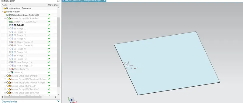
Flange: By adding a flat flange at an angle to a planar face, the sheet metal flange command in Siemens NX may combine two surfaces.
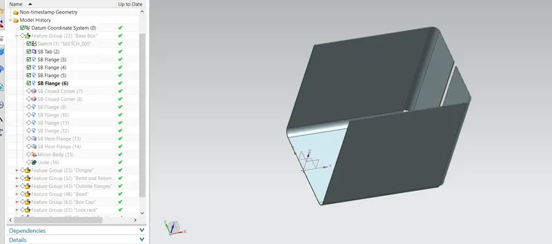
Closed Corner: This tool was used to enclose two or three faces' edges.
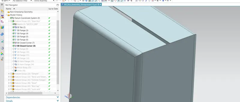
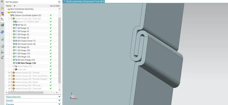
Hem flange: Modify the model by folding a sheet metal flange's edge over into itself for edge rigidity or safe handling.
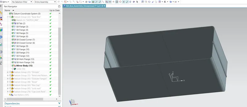
Mirror Body: which mirrors and copies a body across a plane.
Unite: Add the combined volume of two or more distinct solid entities to one body.
Step 2 : Dimple Creation
Tools Used:
Sketch: Sketch generates a 2D visual for the model when there are many sketch commands present, such as lines, rectangles, circles, etc.
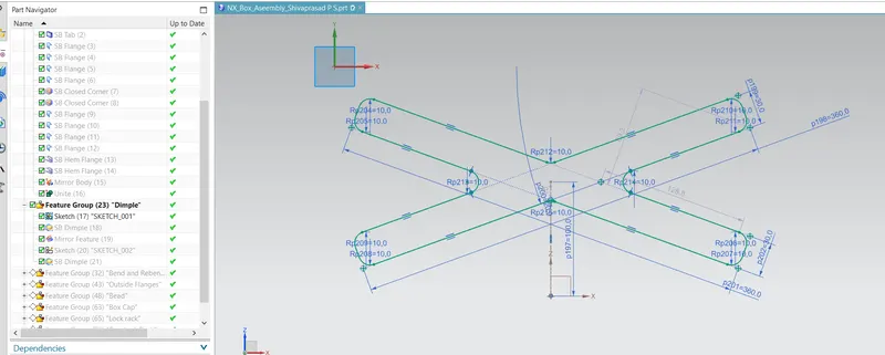
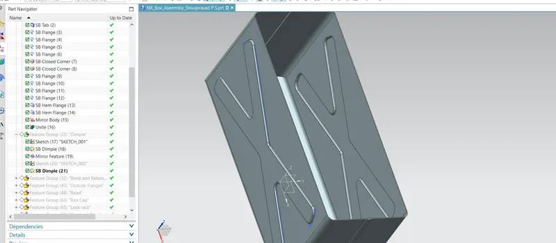
Dimple: Dimples are utilised to strengthen the part's strength. The flat portion of the part is less stiff and weaker. As a result, there is a high likelihood that the component will malfunction. The dimple increases the part's strength and rigidity while lowering the likelihood of default.
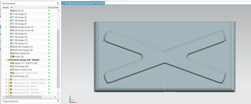
Mirror Feature: which mirrors and copies a feature across a plane.
Step 3 : Unbend & Rebend
Tools Used:
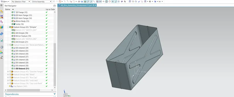
Unbend: Bent metal can be flattened with this feature. To add features to the bent part, we must unbend the body.
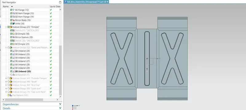
Rebend: The feature is then returned to its initially bent state after the characteristics have been added.
Step 4 : Outside Edge Flange on base box
Tools Used:
Hem flange: Modify the model by folding a sheet metal flange's edge over into itself for edge rigidity or safe handling.
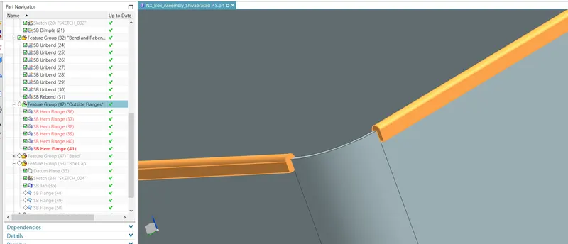
Step 5 : Bead on bottom face
Tool Used:
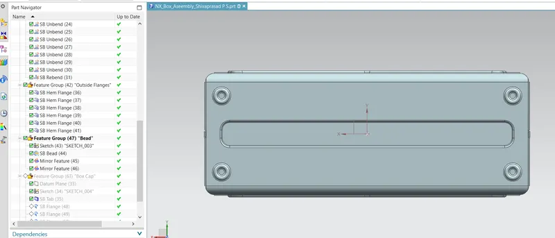
Bead: The material is raised along the lines of the sketch by a bead that looks like a stamping tool.
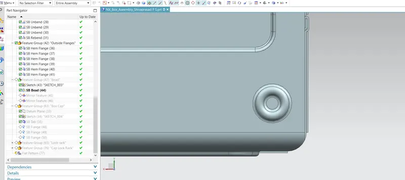
Mirror Feature: which mirrors and copies a feature across a plane.
Step 6 : Creating Cap for Box Assembly
Tools Used:
Datum Plane: Making a datum plane that will be used to build other features with the specified dimensions
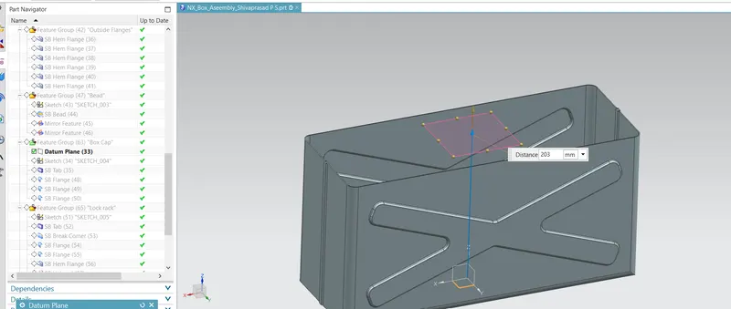
Sketch: Sketch generates a 2D visual for the model when there are many sketch commands present, such as lines, rectangles, circles, etc.
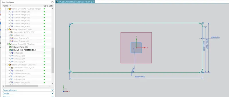
Tab: Tab creates a Base Extrude feature with thickness and direction for the supplied Sketch.
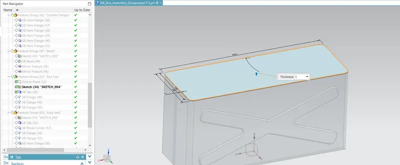
Flange: By adding a flat flange at an angle to a planar face, the sheet metal flange command in Siemens NX may combine two surfaces.
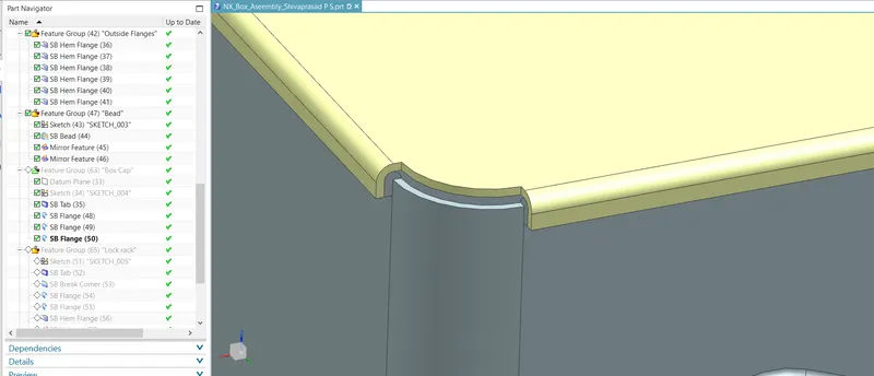
Step 7 : Base Box Lock Rack
Tool Used:
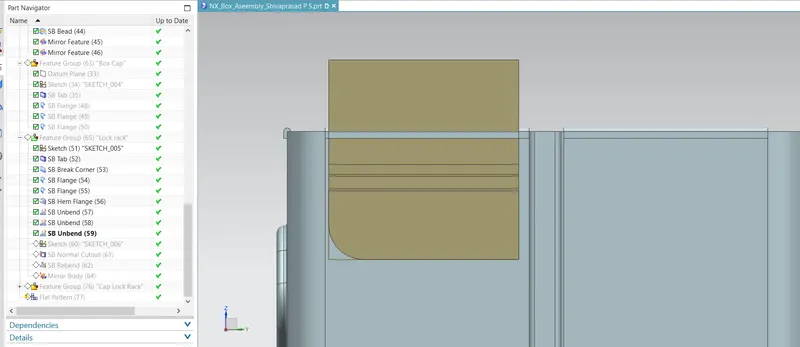
Sketch: Sketch generates a 2D visual for the model when there are many sketch commands present, such as lines, rectangles, circles, etc.
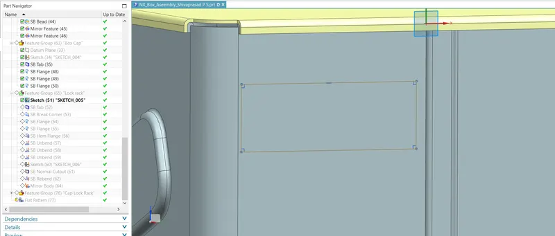
Tab: Tab creates a Base Extrude feature with thickness and direction for the supplied Sketch.
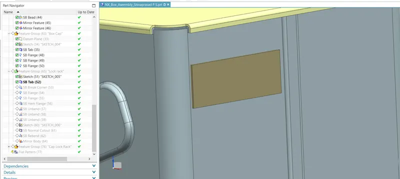
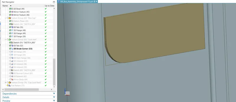
Brake Corner: It is the tool used to chamfer and round the Sharp edges.
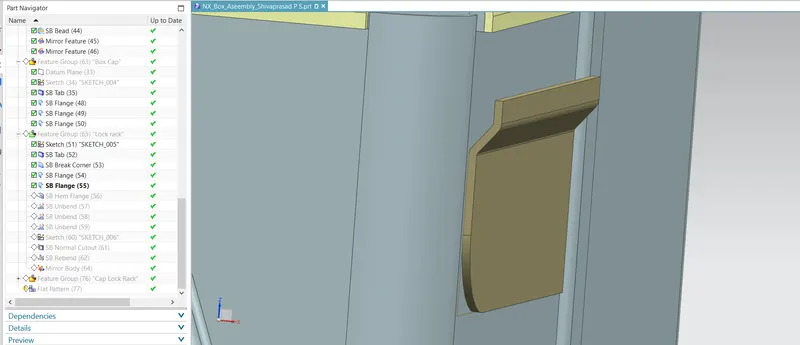
Flange: By adding a flat flange at an angle to a planar face, the sheet metal flange command in Siemens NX may combine two surfaces.
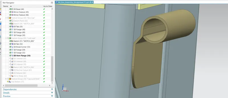
Hem flange: Modify the model by folding a sheet metal flange's edge over into itself for edge rigidity or safe handling.
Unbend: Bent metal can be flattened with this feature. To add features to the bent part, we must unbend the body.
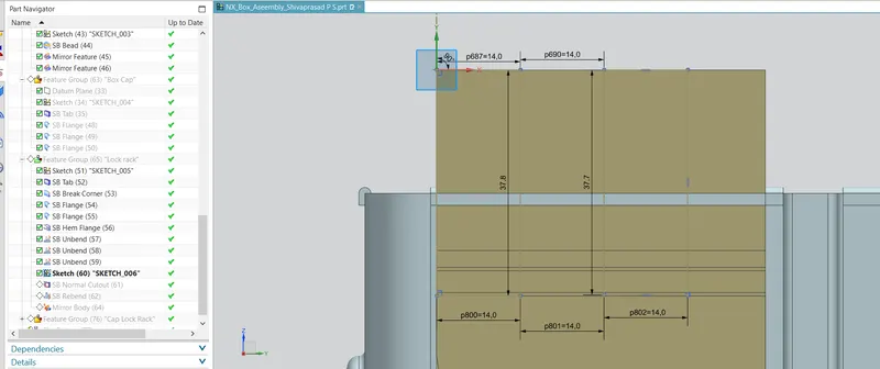
Sketch: Sketch generates a 2D visual for the model when there are many sketch commands present, such as lines, rectangles, circles, etc.
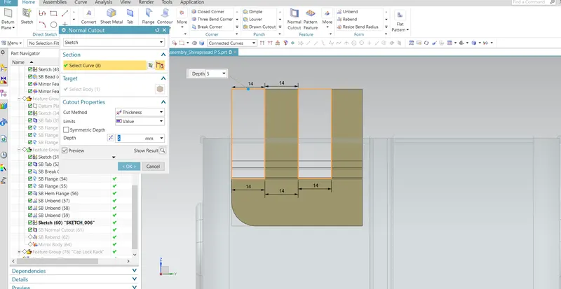
Normal Cutout: Normal Cutout commands use the principles of sheet metal manufacture to extract volumes from the sheet. Cutting faces will be parallel to the surface of the sheet metal.
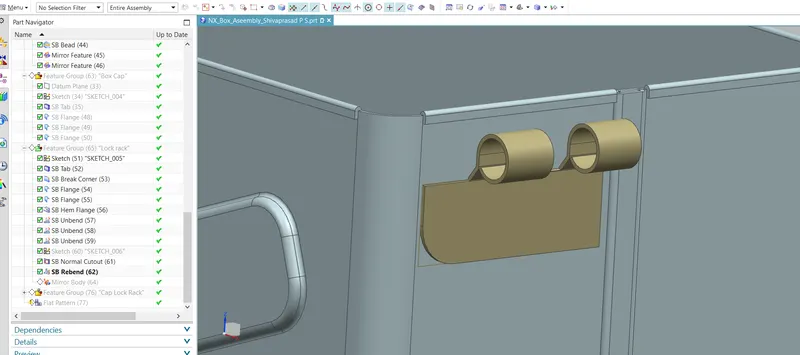
Rebend: The feature is then returned to its initially bent state after the characteristics have been added.
Mirror Body: which mirrors and copies a body across a plane.
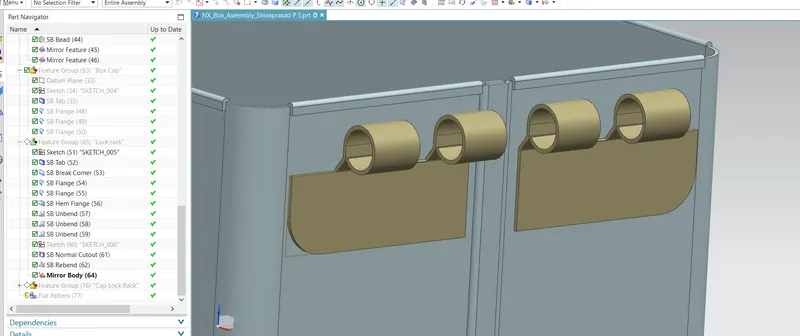
Step 8 : Cap Lock Rack
Tool Used:
Sketch: Sketch generates a 2D visual for the model when there are many sketch commands present, such as lines, rectangles, circles, etc.
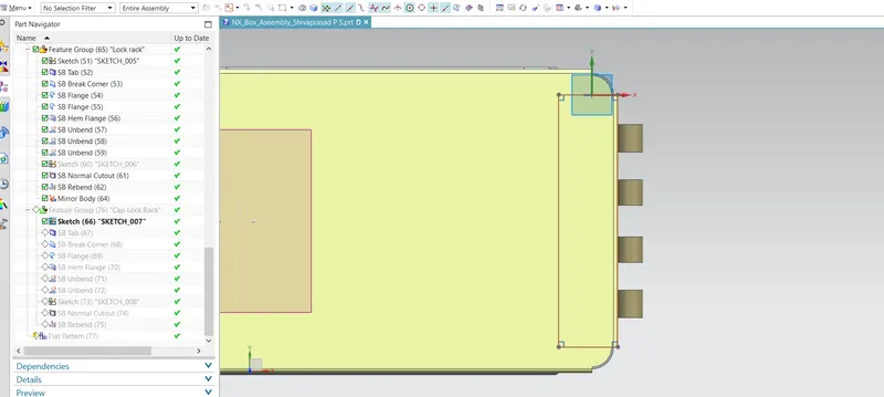
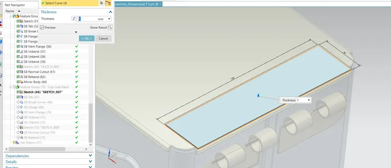
Tab: Tab creates a Base Extrude feature with thickness and direction for the supplied Sketch.
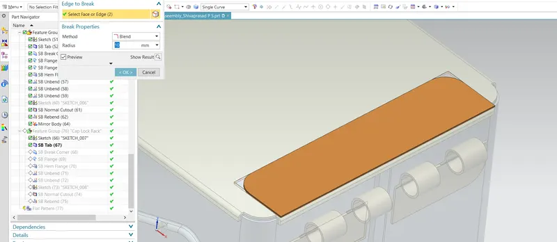
Brake Corner: It is the tool used to chamfer and round the Sharp edges.
Flange: By adding a flat flange at an angle to a planar face, the sheet metal flange command in Siemens NX may combine two surfaces.

Hem flange: Modify the model by folding a sheet metal flange's edge over into itself for edge rigidity or safe handling.
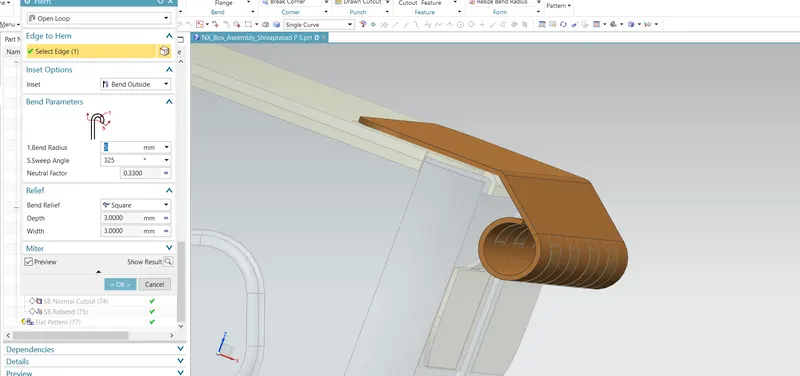
Unbend: Bent metal can be flattened with this feature. To add features to the bent part, we must unbend the body.
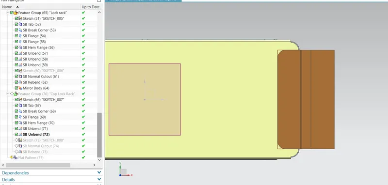
Sketch: Sketch generates a 2D visual for the model when there are many sketch commands present, such as lines, rectangles, circles, etc.
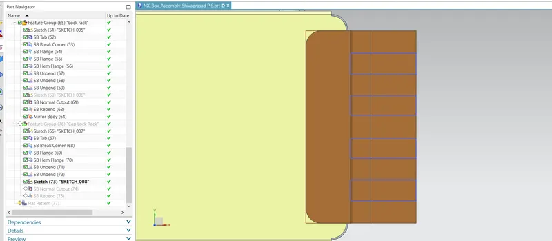
Normal Cutout: Normal Cutout commands use the principles of sheet metal manufacture to extract volumes from the sheet. Cutting faces will be parallel to the surface of the sheet metal.
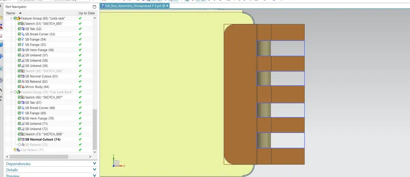
Rebend: The feature is then returned to its initially bent state after the characteristics have been added.
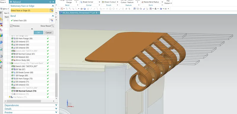
Step 9 : Flat Pattern
A flattened pattern of the sheet metal item is made to be used in drafting.
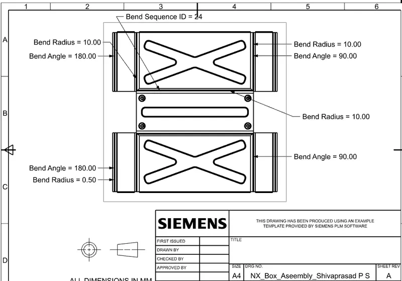
Views:
Isometric Views
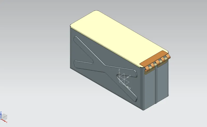
Front View
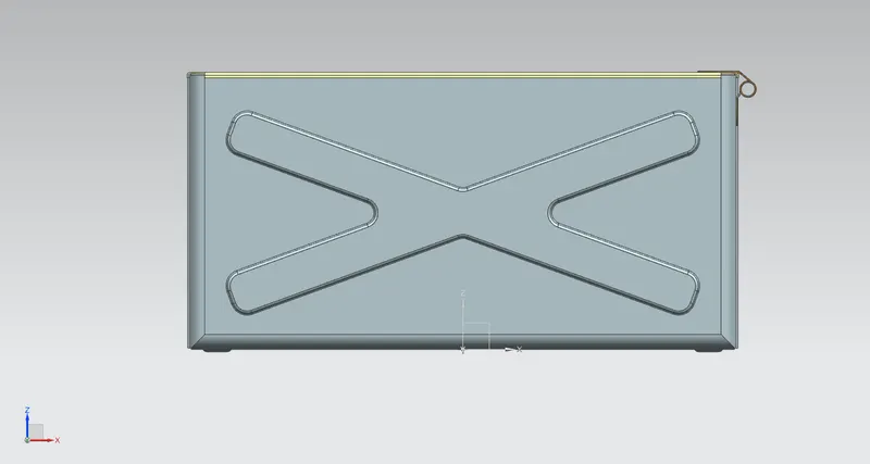
Left View
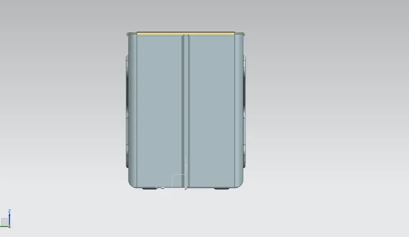
Right View
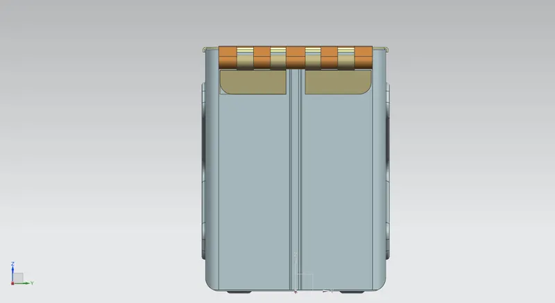
Top View
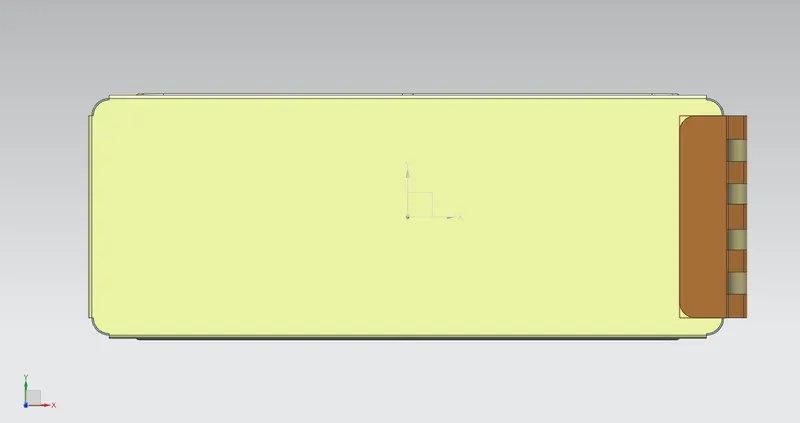
Drafting:
Conclusion: Hence the box assembly is designed with the use of several commands, such as mirror feature, hem flange, mirror body, flange, and tab, through this challange.