Advanced Sheet Metal Design Using NX Cad Challenge_2_Box Assembly
BOX ASSEMBLY DESIGN USING NX CAD
OBJECTIVE:
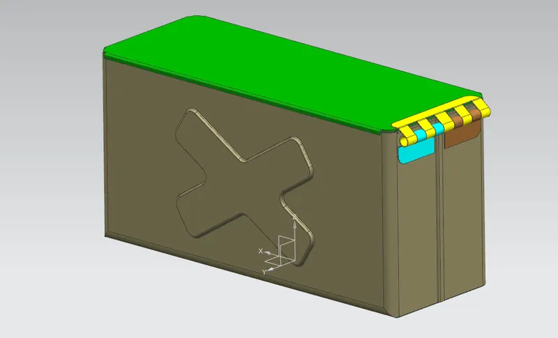
The main objective of this project is to design a sheetmetal Box Assembly in NX Cad sheet metal application workbench.Also to perform the drafting for casing part.
INTRODUCTION:
Sheet metal is metal formed by an industrial process into thin flat pieces sheet metal is one of the fundemental forms used in metalworking and it can be bent to various shapes. Thickness can vary significantly extremely thin sheets are considered as foil or leaf and pieces thicker than 6mm are considered plate steel or structural steel.
The sheet metal application in NX CAD provides an enviorment for the design of sheet metal parts used in machinery,Automotive and Areospace.Enclosures ,Brackets and the other parts are normally manfactured with break press.The sheet metal application widely used every industry i.e mining,construction,farming,catering,hospitality,shipping,manufacturing,aviation,medical and transport.
In sheetmetal application we can create uniform thickness parts using basic features such as flange , tabs,and jogs.the complex sheet metal part can be designed in the solid model work benchand can be converted to sheet metal part. We can also import ,clean up and covert a non cheet metal part into a sheet metal part.Flat pattern sheet metal data can be used for manfacturing process . the material parameters such as thickness bend radii and bend relief can easily set as default settings.
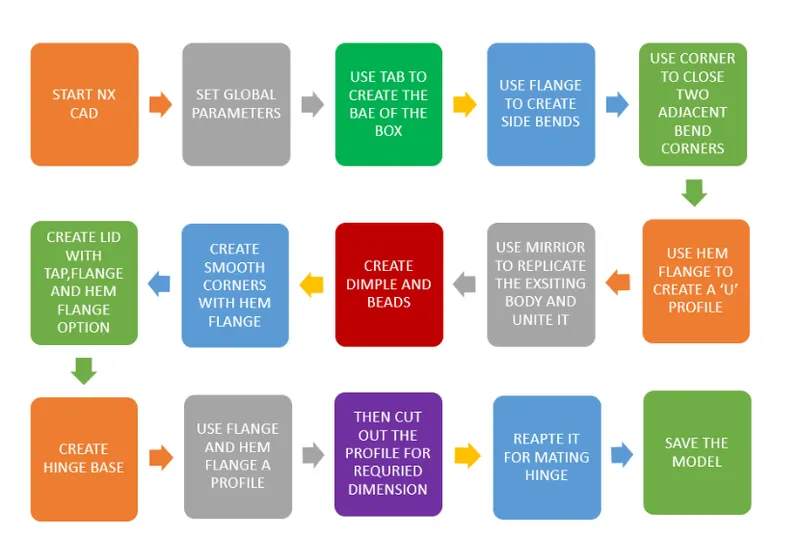
DESIGN METHODOLOGY:
DESCRIPTION:
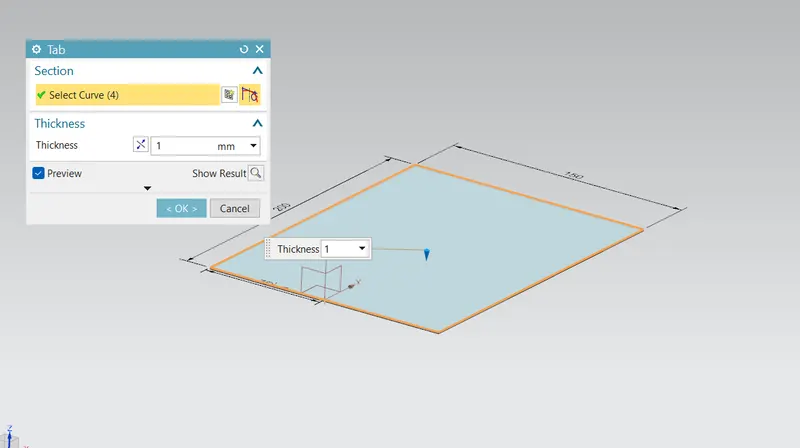
Design a base sketch for box and create a base with tab option
TAB:this command is used to create the base feature by extruding the sketch along a vector by a thickness value
Use flange option to form the sides for box.
FLANGE: This command is used to add a flat flange at an angle to the planar face and add a bend between the two.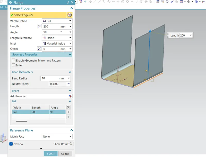
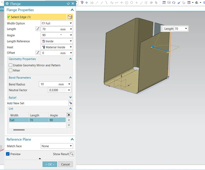
Then apply a closed corner at adjacent bends for both sides .
Closed Corner: This feature helps to close a corner where two adjacent bends meet.
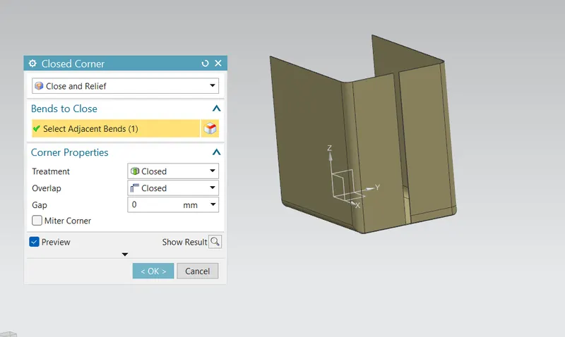
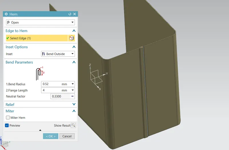
After closing the corner use hem flange to create a U profile which self-locks the sheet metal after bending.
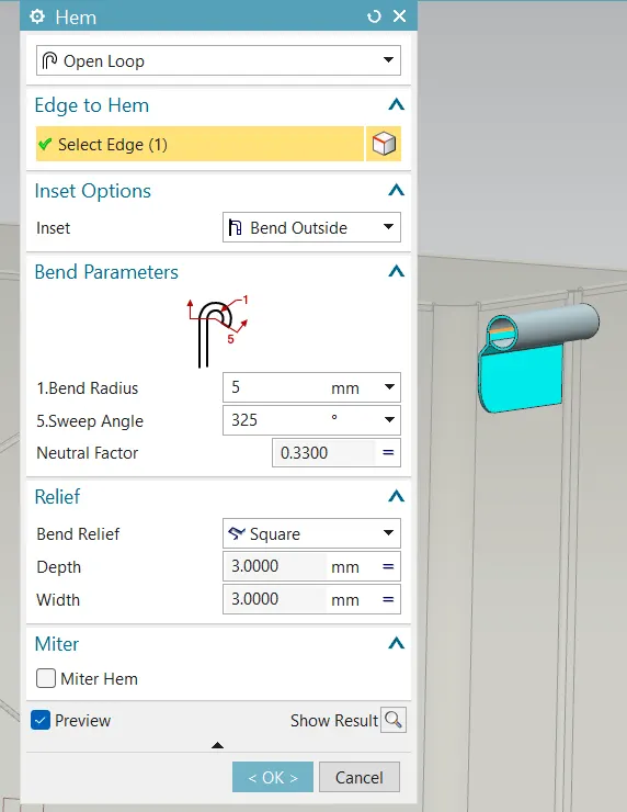
Hem Flange: Hem flange is used to modify the model by folding the edge of sheet metal flange over onto itself.
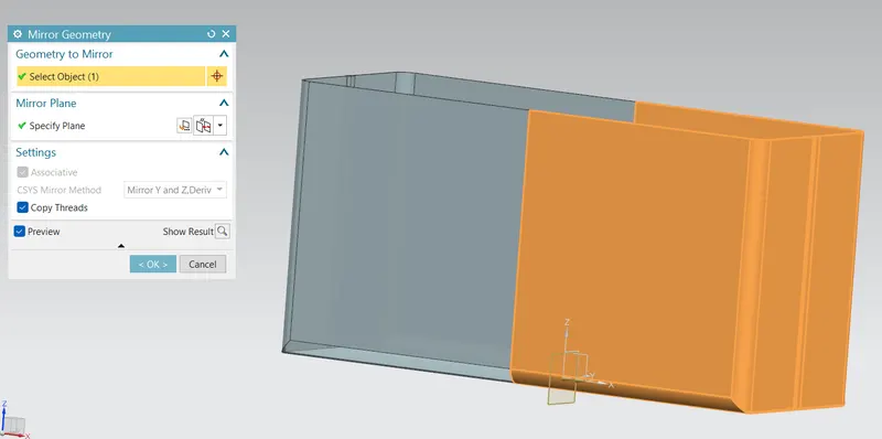
Now mirror the body to form a replicate of existing body using mirror geometry option.
Mirror geometry: this feature mirrors the selected geometry and features across selected planes or lines.
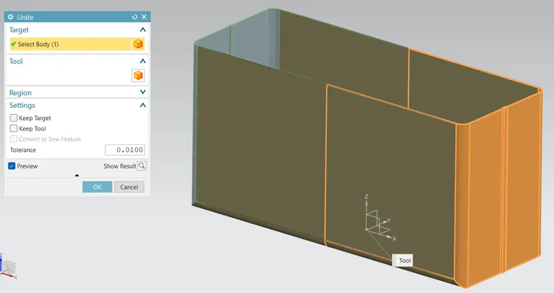
the unite the bodies existing body and mirrored body
Unite: This feature used to unite selected bodies into single body.
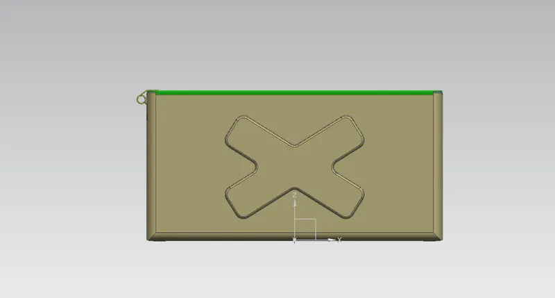
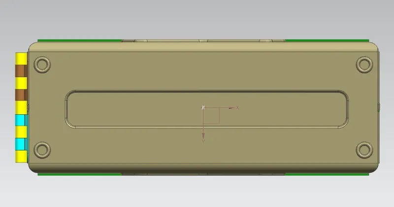
Now create a sketch and make a dimple on the front and bottom side of the box and mirror it on the backside.
Dimple : This is one of punching processes which is used to raise an area of the model perpenducular to face where contour sketch is drawn.
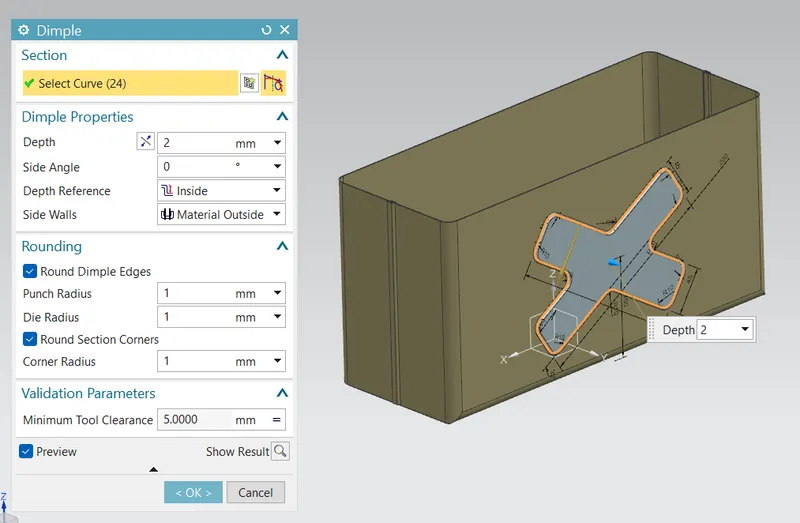
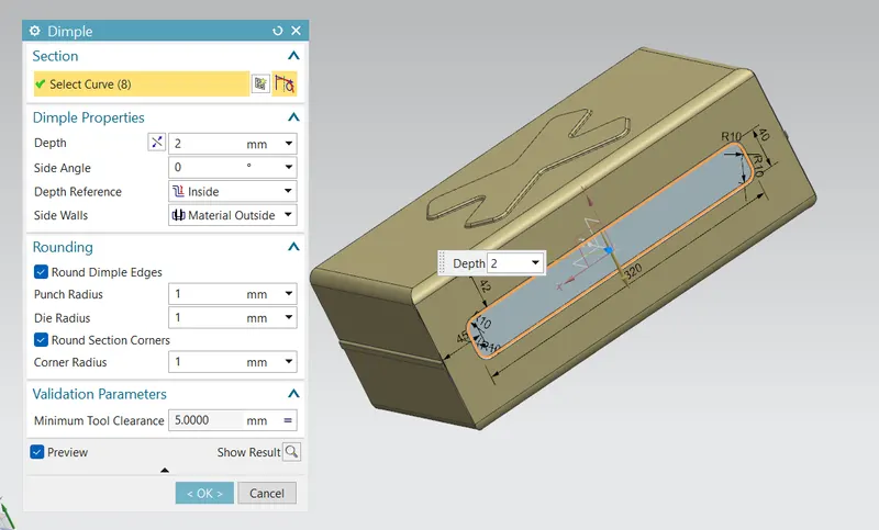
Then create a sketch for creating beads .then select bead optionwith circular cross section and mirror it on other three corners.
BEADS : this are used to lift a material along the contour of the sketch.
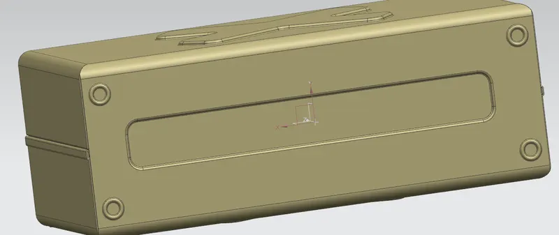
Then use hem flange at top edges to create a U shaped corners which neglect the sharp edges and create a smooth and safe edge.
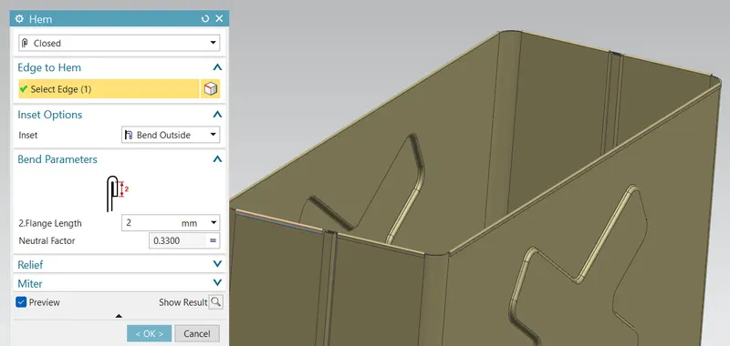
hence box lower part design is done.
LID
Now for lid Create a datum plane which is offseted from xy plane at 203mm distance
then create a sketch on new plane create a base with tab option.
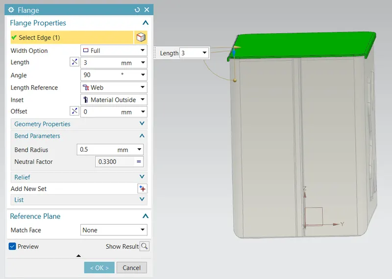
Use flange to create the bends in the lid which seats on sides of box.
HINGE
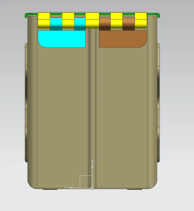
Using right side face of the box as reference , create a base for the hinge using tab option.
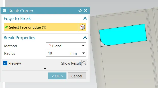
then use break corner option to avoid sharpe edges.
BREAK CORNER: This command is used to round or chamfers sharp corner of a tab or flange.
Then using the flange and hem flange , create a circular profile with dia where the hinge rod gets inserted to lock.
After creating flange , unbend the profile with use bend of unbend option.
UNBEND: This command is used to unbend the sheet metal. the punching operation can be performed only by unbending the sheet metal.
Create a sketch that has to cutout from profile with normal cutout option.
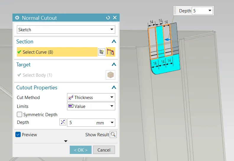
Then rebend the model and mirror it to get the best view of model with replication of existing body.
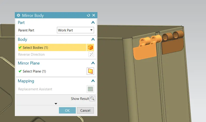
Likewise create a mating hinge by taking top side of lid as reference for creating tab.
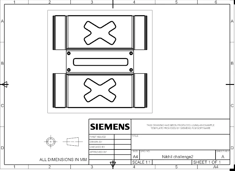
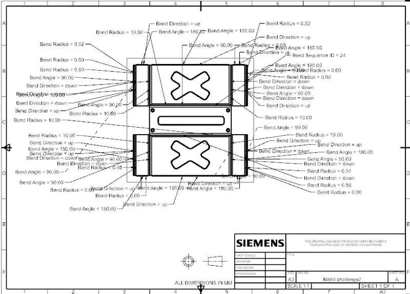
FLAT PATTERN:This is used to create a qutomatically flattened version of sheet metal parts and this is taken for drafting purpose which is used for reading model.
then go to drafting option then choose A4 sheet and oreint it to fit to sheet.
thus whole Box assembly model completed .