Advanced Sheet Metal Design Using NX Cad Challenge_2_Box Assembly
BOX ASSEMBLY DESIGN REPORT
Objective:
To design the Box Assembly by using the NX 12.0 (NX Cad Challenge_2_Box Assembly).
Introduction:
Siemens NX CAD sheet metal design software incorporates material and process information in sheet metal-specific modeling features such as Tab, flanges, Bend, Closed Corner, Hem Flange, Mirror feature, Unite, Cutouts, Dimple, Beads, Break Corner and edge treatments, and other formable features.
In this challenge, the box assembly consists of three parts.
1) Box (Main Body)
2) Lid
3) Hinge
This challenge is designed by NX 12.0 software.
Design Methodology:
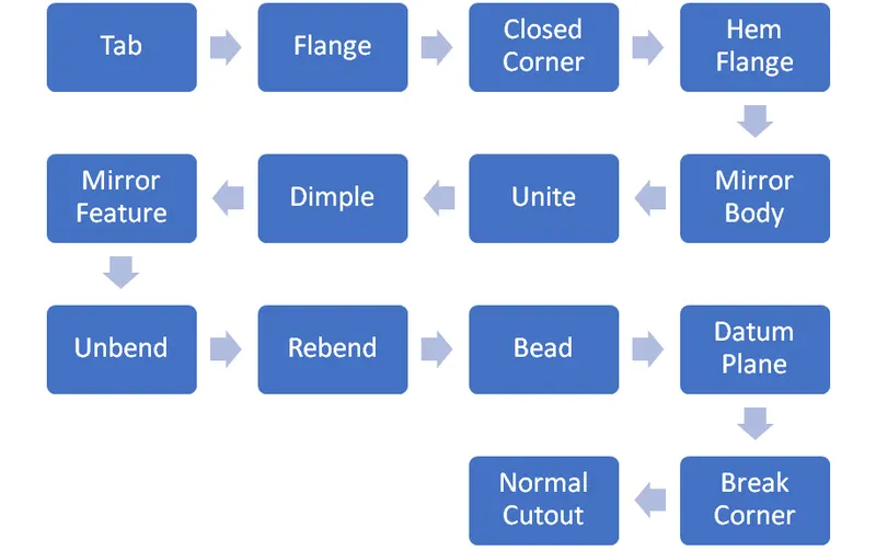
This Design considers the features such as Tab, Flange, Closed Corner, Hem Flange, Mirror Geometry, Unite, Dimple, Mirror Feature, Unbend, Rebend, Bead, Datum Plane, Break Corner, Normal Cutout and Drafting. The design methodology used for this challenge can be summarized as depicted in the flowchart mentioned above image.
Feature Description:
1) Box Assembly:
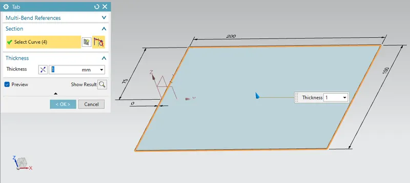
Tab:
- The tab is most used to design the base solid by using sheet metal.
- I created the tab by using the sketch on the XY plane having the dimensions are 150*200.
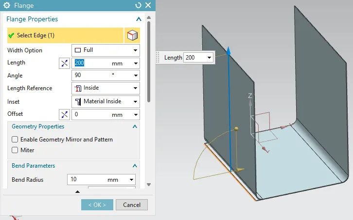
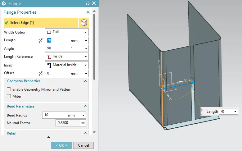
Flange:
- The flange is external or internal edges or rim for strength as the flange and selects the edge to add the flat flange.
- Apply the same flange to the corresponding symmetric edge of the sheet metal.
- I created two flanges with 200 mm length normal to the XY plane and then another flange with 70 mm was created normal to the ZX plane.
Closed Corner:
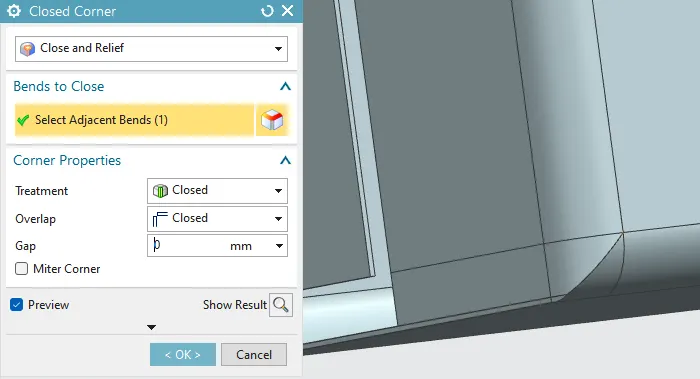
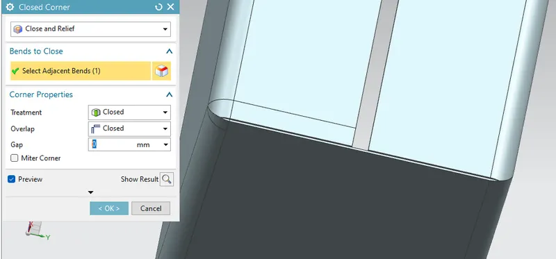
- The closed corner is used for the closed corner where two adjacent faces of the flanges meet by extending the bends and flanges.
- For this box assembly, I used the closed corner feature twice to close the open corners at the bottom portion of the flanges.
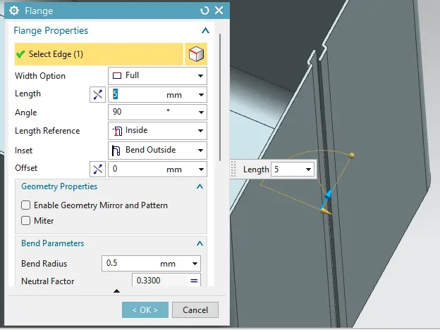
Flange for fastening:
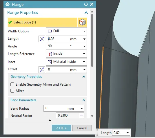
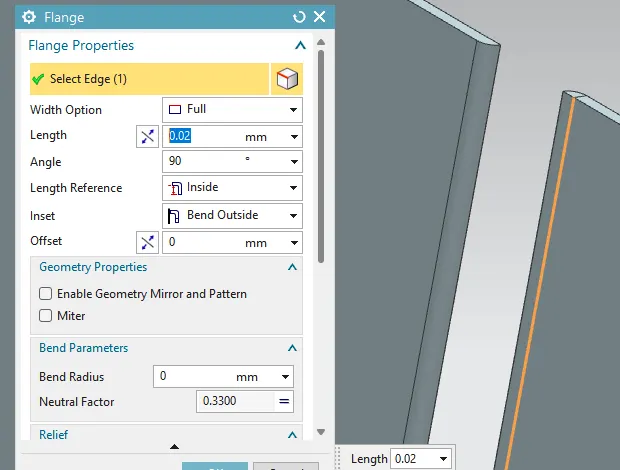
- For fastening or connecting the two flanges on side of the box assembly.
- I first created the flange with a length is 0.02 mm and another flange is created at 5 mm length with an outside bend.
Hem Flange:
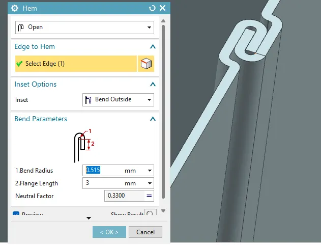
- Hem flange is used to modify the design by folding the edge of a flange.
- The main purpose of this feature for increase stiffness and safe handling.
- For this box assembly, I created the hem flanges with a 0.515 mm bend radius and length is 3 mm.
Mirror Geometry:
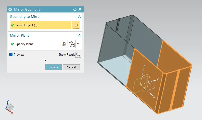
- Now half part of the box assembly was designed remaining the half was designed by using the mirror geometry feature, which saves a lot of time.
- I used to mirror geometry feature to mirror the half body of the YZ plane.
Unite:
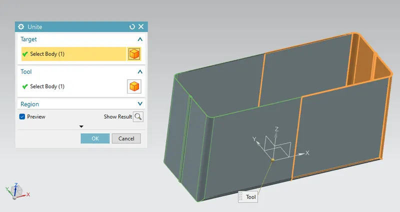
- Unite is used for the two different bodies are combined to the single body.
- I used unite feature to combine the body before the mirror and after the mirror geometry feature.
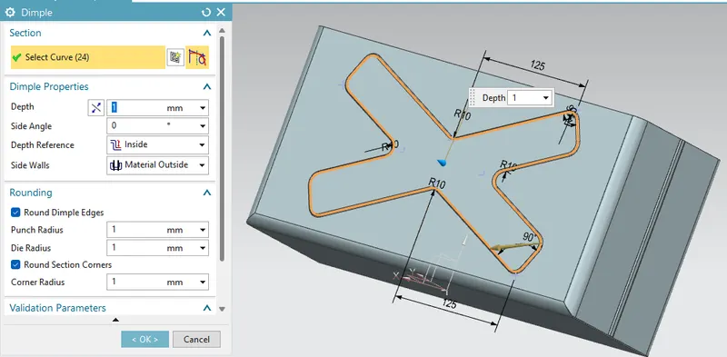
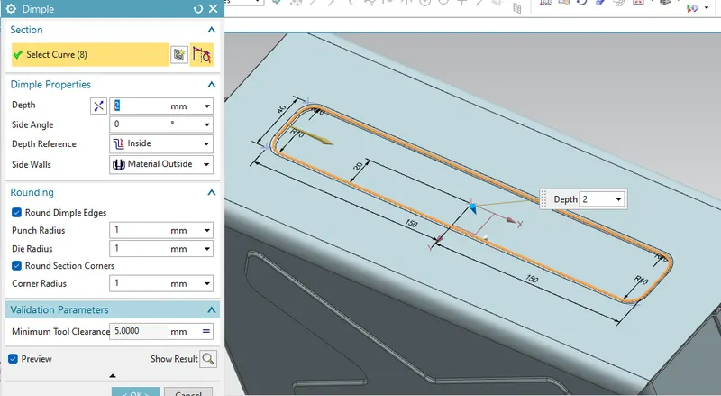
Dimple:
- Dimple feature that lifts an area along the contour of a sketch that forms a stamping tool.
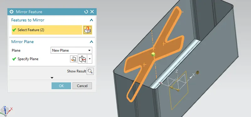
Mirror Feature:
- Another dimple is created by using the mirror feature that is normal to the ZX plane.
Unbend:
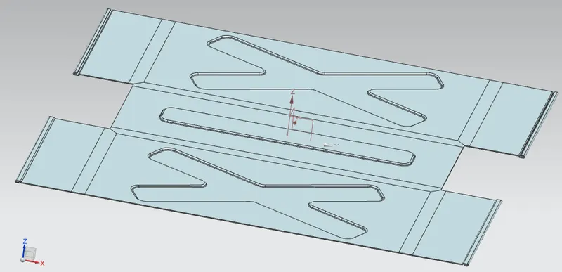
- Unbend is a very useful tool in the NX-CAD. In the Unbend dialog box, select as stationary face the larger horizontal (inside the plane) face of the metal sheet.
- Select the Bend face one of its adjacent faces.
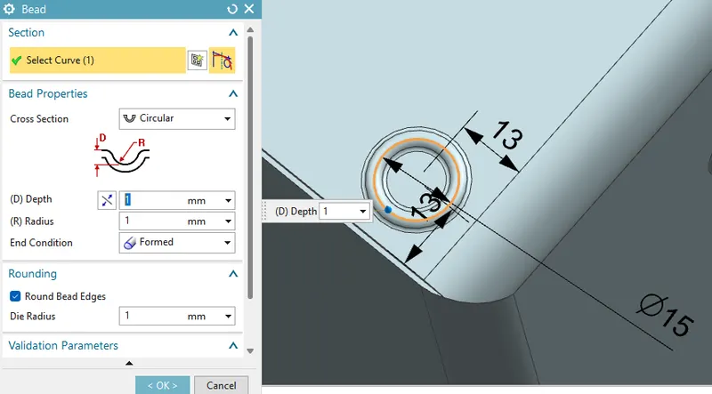
Bead:
- Bead is created to conture shape according to the sketch in the required direction with a required punch.
- For this design, one bead was created near the bottom left corner having a diameter is 15 mm.
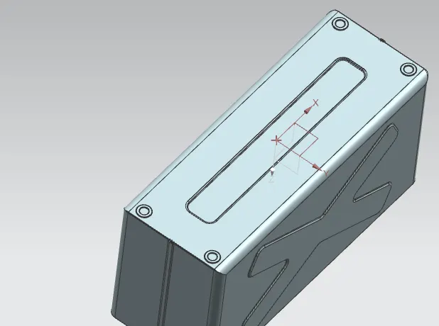
- Then it was created by using the mirror option that is normal to the ZX plane and YZ plane to obtain the four beads on each corner.
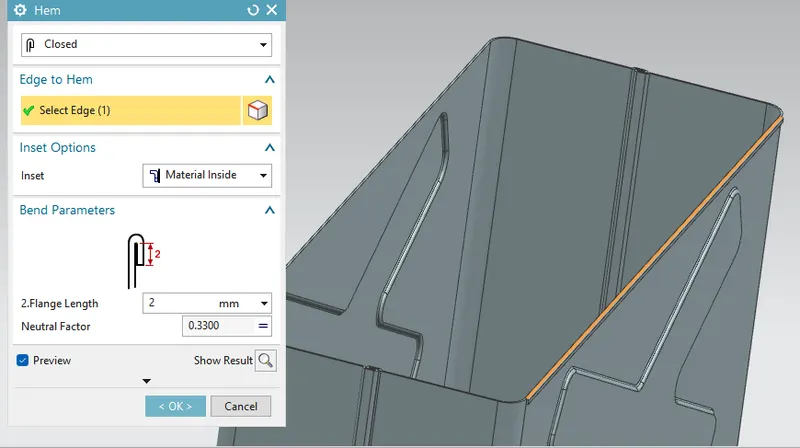
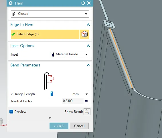
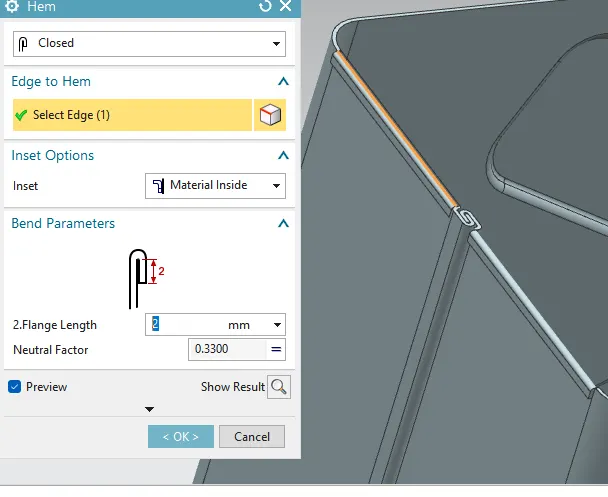
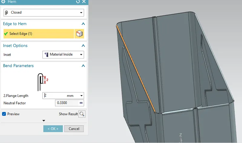
Hem Flange:
- At this stage, hem flange is used for the created rounded edge at the top and it helps in the easy handling.
2) Lid Creation:
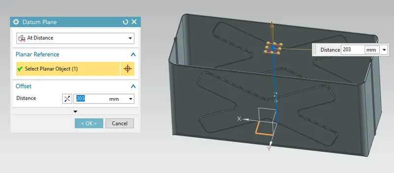
Datum Plane:
- For creating the lid for the box, the datum plane was created at a distance is 203 mm from the XY plane
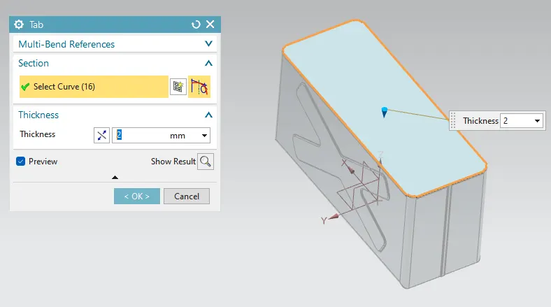
Lid Tab:
- The sketch was created by taking the reference edges from the top view of the box design.
- Then the base tab was created by using the sketch option.
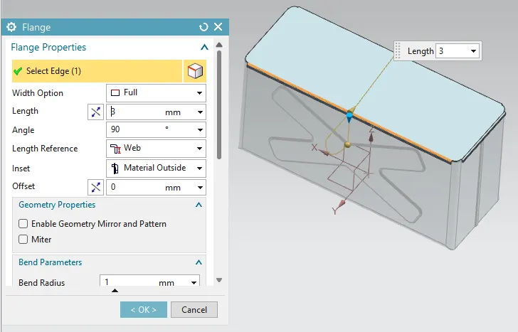
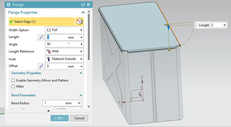
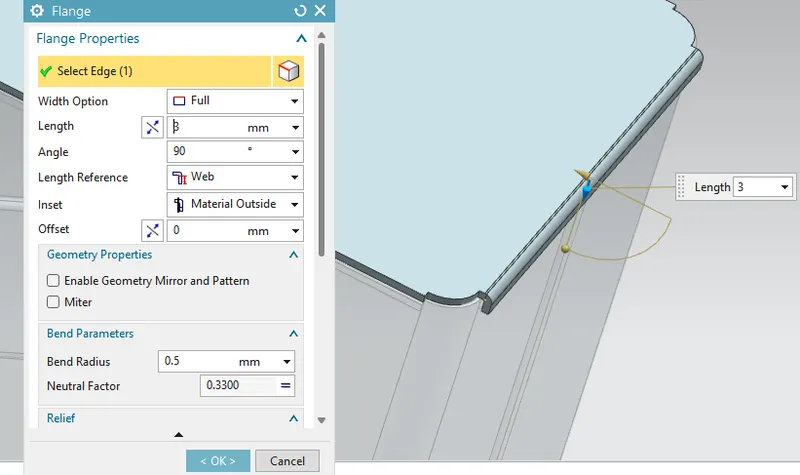
Lid Flanges:
- For a closing box with proper alignment flanges having a web length of 3 mm were added to both sides and backside.
3) Bottom Hinge Creation:
Hinge Tab:
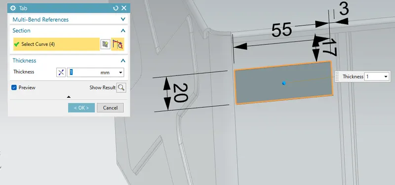
- A rectangular tab was created by using a datum plane.
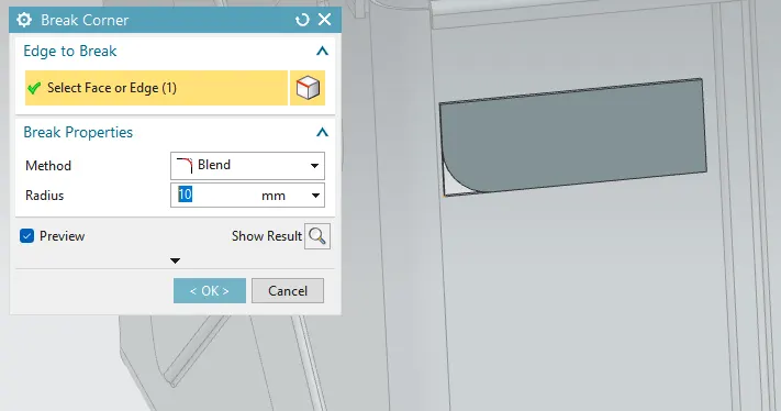
Hinge Break Corner:
- The break corner feature breaks the sharp edge in the corner and makes it round.
- Break corner helps to prevent stress relief and fracture breaking and I used a blend radius is 10 mm.
Hinge Flanges:
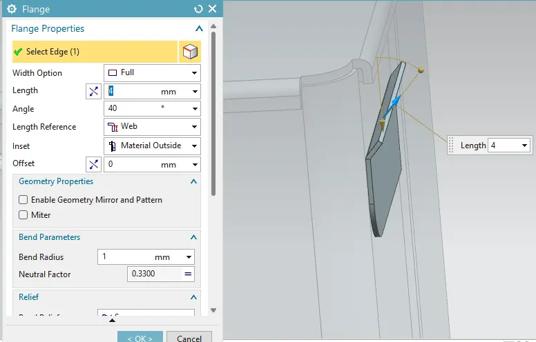
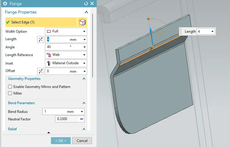
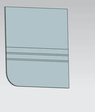
- For obtaining the required two flanges of 40-degree bend each of the lengths is 4 mm were created adjacent to each other.
Hem Flange:
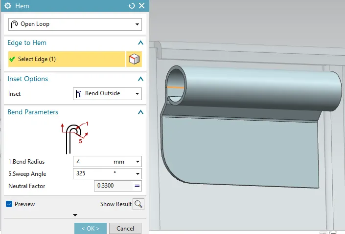
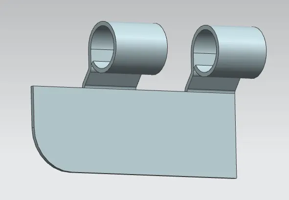
- For creating the hinge for the box lid an open bend outside type flange with a radius of 5 mm and sweep angle of 325 degrees was added to the end of the last flange.
Unbend, Normal cutout & Rebend:
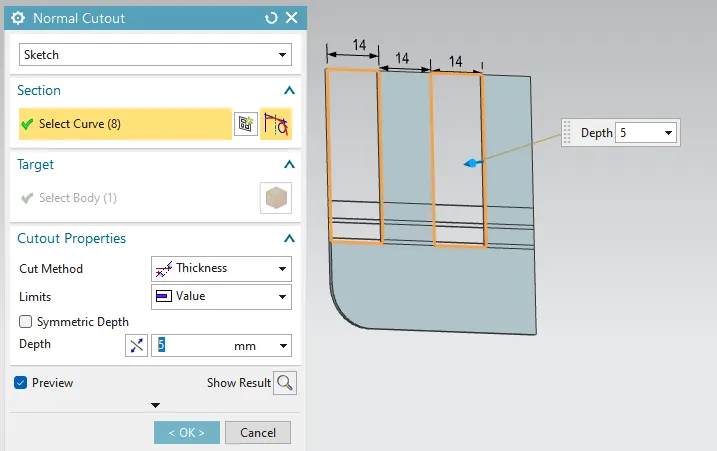
- Flattened hinge portion to perform normal cutout and then the rebend to get hinge in its original position.
Mirror Body:
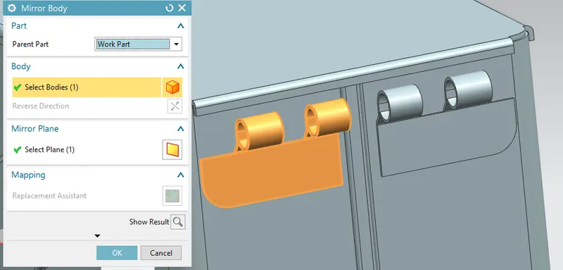
- Now one hinge body was designed and another hinge body was created by using the mirror body
Upper Hinge Creation:
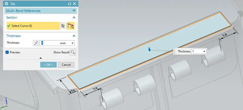
Tab:
A single rectangular tab was created on the top surface of the lid.
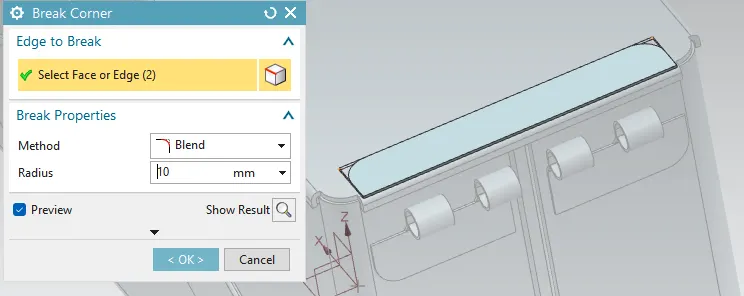
Hinge Break Corner:
- The break corner feature breaks the sharp edge in the corner and makes it round.
- Break corner helps to prevent stress relief and fracture breaking and I used a blend radius is 10 mm on both sides of the corners.
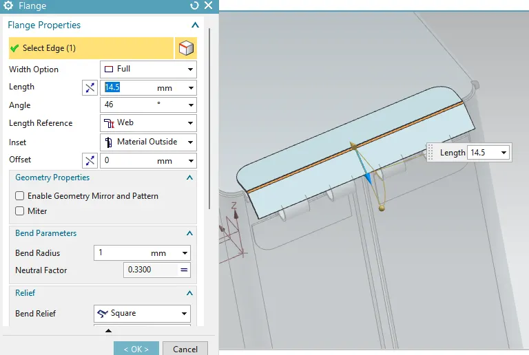
Flange:
- The flange is similar to the bottom hinge, a flange was also added to the upper tab at 46 degrees and the length is 14.5 mm.
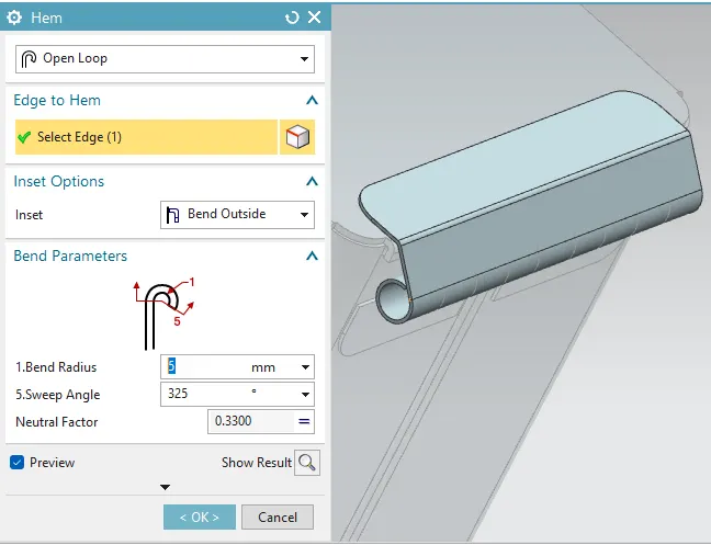
Hem Flange:
- The flange is similar to the earlier process, an open hem flange of radius 5 mm with an angle is 325 degrees were created.
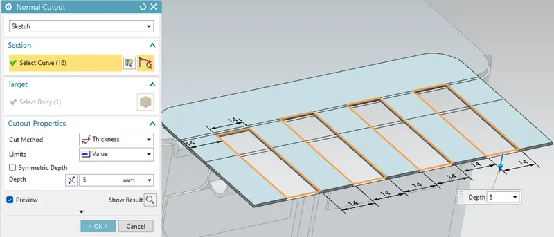
Normal cutout:
- As per requirement material is removed in the form of four rectangles by using a normal cutout for creating the hinge barrel.
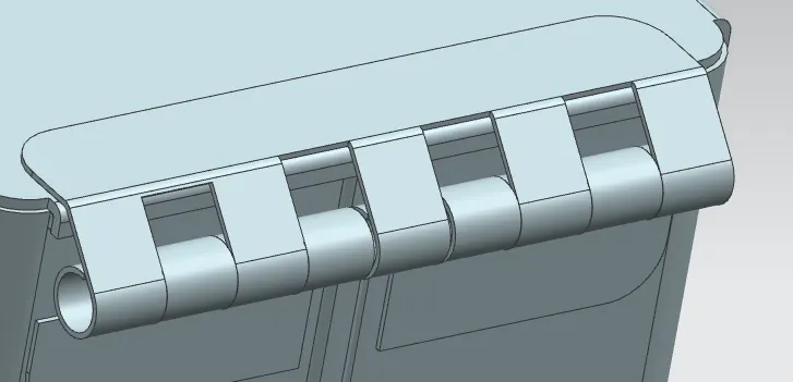
Rebend:
- The upper tab Hinge barrel was created by using the rebend is bring the original position.
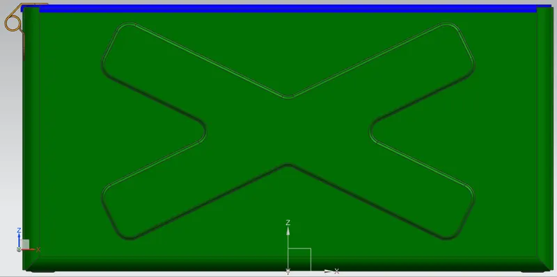
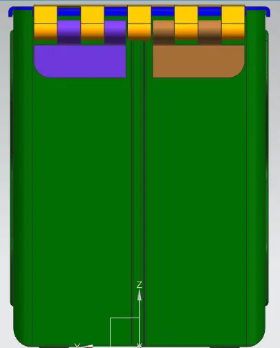
Various Views of Box Assembly:
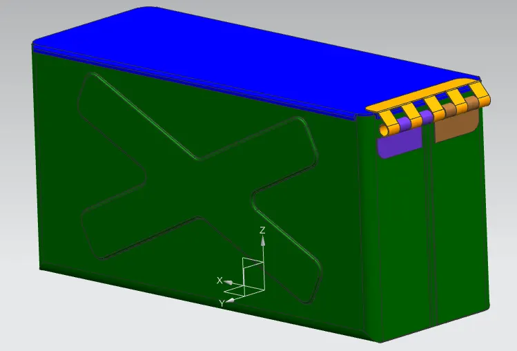
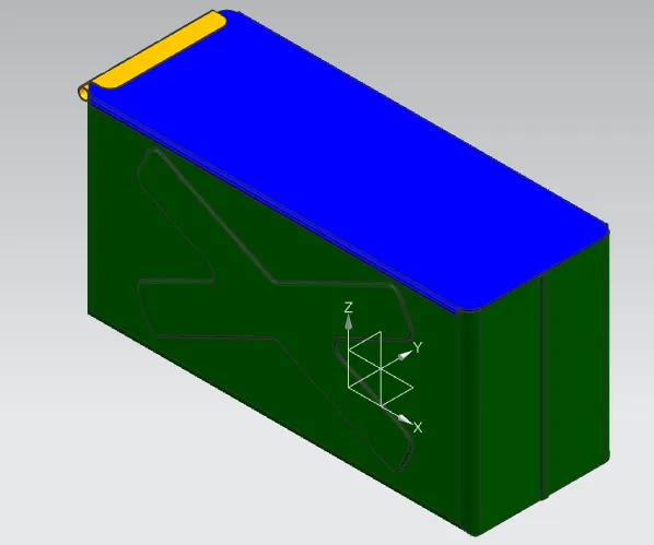
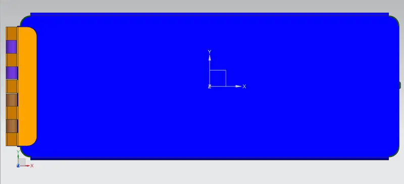
Draft Drawing:
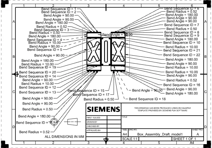
- After the modeling, the manufacturing of the component a technical 2D drawing of the component with accurate dimensions or scales is denoted.
- The draft is created with a scale of 1:2 and using A4 size. and add a new Base View.
- In the Base View dialog box, select the option Model View to use FLAT-PATTERN#1.
- Set the scale ratio is 1:10.
Final Conclusion:
- Box Assembly Design is completed by using the sheet metal and its application tools such as Hem flange, Closed corner.
- I got an understanding of the design methodology to create the box assembly and successfully completed it for Box Assembly.
- All the basic features are prepared to create the box assembly design.
- This challenge is finished by using NX-12.0 (Unigraphics Design).