Advanced Sheet Metal Design Using NX Cad Challenge_2_Box Assembly
CHALLENGE-2
ADVANCE SHEET METAL DESIGN USING NX CAD-CREATE BOX ASSEMBLY
Aim: Create a box assembly using the NX-CAD as per the provided data. Also provide a detail report on the manufacturing technique used in the challenge.
Comment:
Manufacturing technique used in the present challenge
A variety of operation i.e., bending, hemming, cut, punched rolled etc., were used to create the provided box.
Steps used in the NX-CAD for creating the BOX-ASSEMBLY
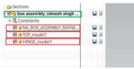
1. First Box assembly file was created and marked with green box and then three model file were created under the assembly file marked with the red box.
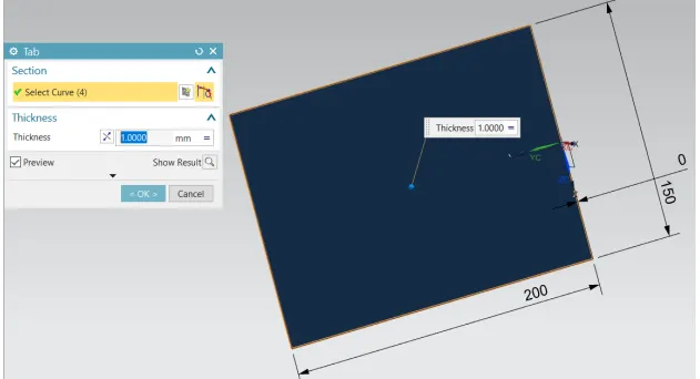
2. Create base tab as per the given dimension.
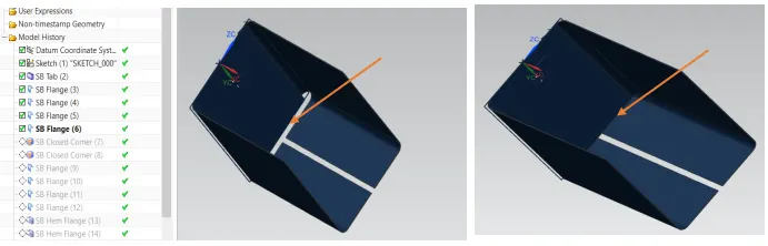
3. Use the flange operation to create the three legs to the base surface and closed corner operation used to close the space marked by the arrow.
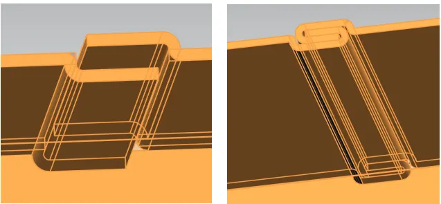
4. Flange and hem flange operation were used to create the locking presented in the below figs. And the created part was mirrored. Further the component was unbdended and rebended.
5. Further, the operation Dimple and Bead used to lift the material from the base material. This operation provide the additional strength to the sheet metal part.
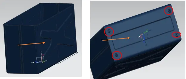
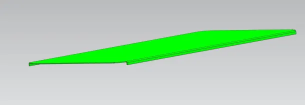
6. Top cover was created separately and presented in the below fig. The wave geometry linker commend used to create the outer part from the box, which was created in the previous section. Further the flange commend used to give side coverage to the box.
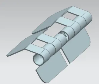
7. Further the hinge was created separately using the wave geometry linker commend. Additionally flange, hem, normal cutout, break corner, unbend and re-bend operations were used to create this part.
8. Full assembly
Different view of the Box Assembly
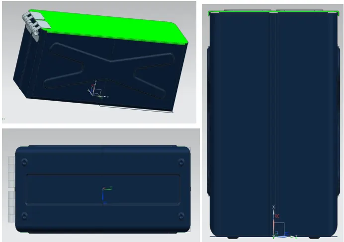
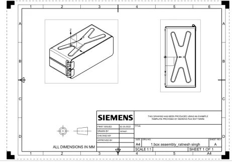
9. At the last use the flat pattern operation to get the actual sheet dimension of the blank sheet. Then use
the drafting commend to provide the drawing for the manufacturing purpose.
Conclusion: As per the given dimension and detals box assembly was created in the NX-CAD using the different commend.