Advanced Sheet Metal Design Using NX Cad Challenge_2_Box Assembly
Title: Box Assembly
Objective: Design of the Box Assembly using Nx CAD.
Introduction: The design of Box assembly is designed using NX CAD according to the industry standards of the design of sheet metal and process. Basic Principles Sheet Metal Fabrication is the process of forming parts from a metal sheet by punching, cutting, stamping, and bending. 3D CAD files are converted into machine code, which controls a machine to precisely cut and forms the sheets into the final part.
Design Methodology:
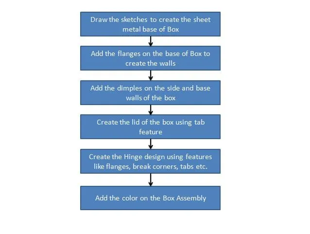
Description of tools and features used in Design of the Box Assembly:
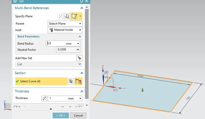
Create a sketch of a rectangle of 200mm length and 150mm breadth on the XY plane.
Use the Tab feature and create the sheet metal base of the box.
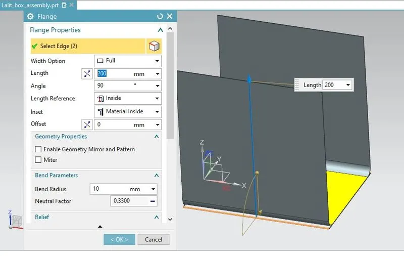
Create the flanges of 200mm length with a bend radius of 10mm to create the sidewalls of the base.
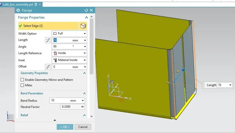
Create flanges of 70mm length with a bend radius of 10mm on the side walls.
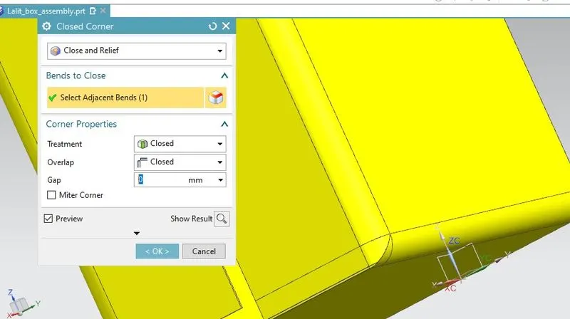
Use the closed corner feature to close the corners of the box.
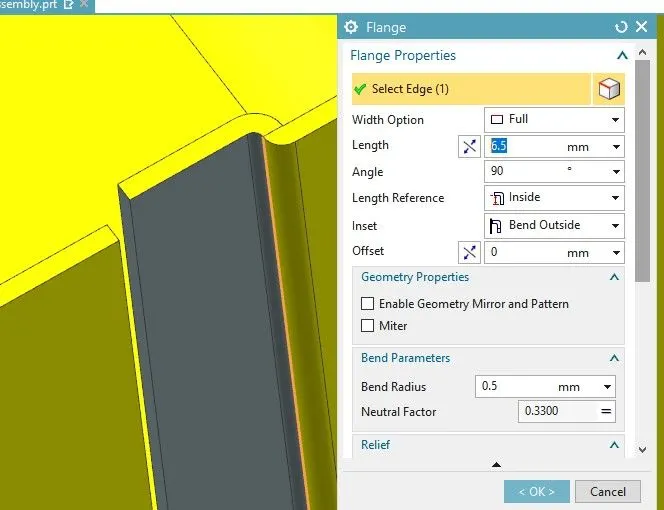
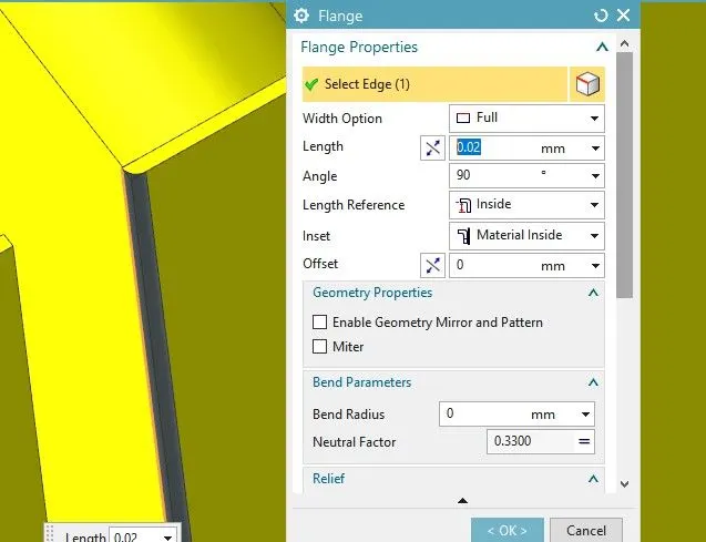
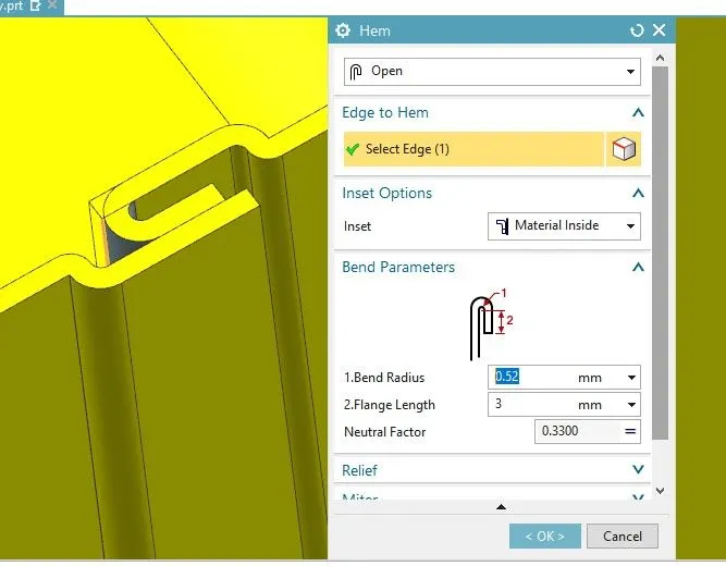
Use Flange and Hem Flange features to create the flanges.
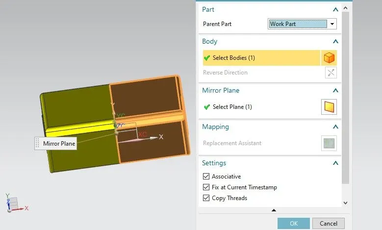
Use the Mirror Feature and mirror the body about the ZY plane.
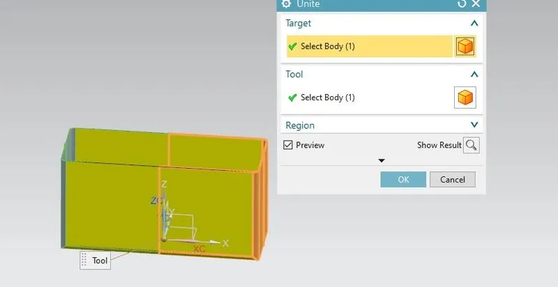
Use Unite feature to join both the body.
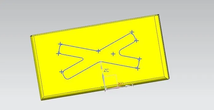
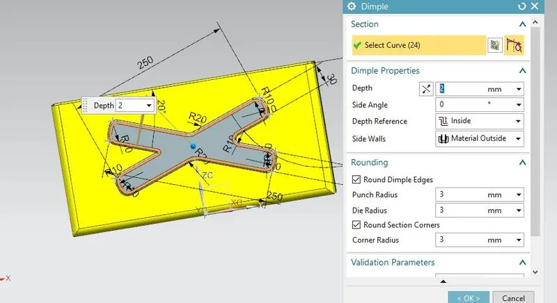
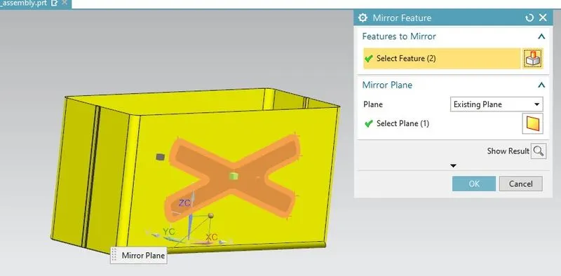
Create the sketch on the sidewalls of the box and add dimples using the Dimple feature.
Use the Mirror Feature and mirror the dimple about the ZX plane.
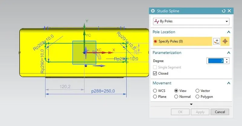
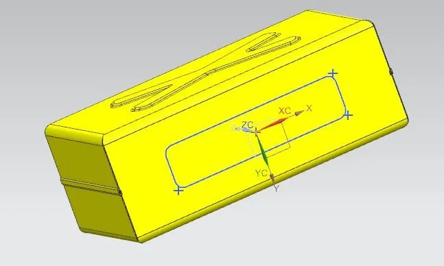
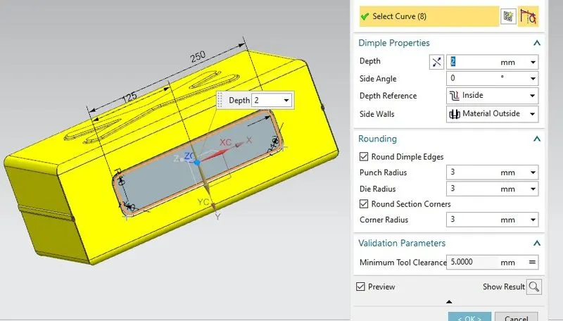
Create the sketch on the base of the box and add the dimple on the base.
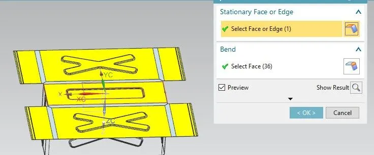
Unbend and Rebend the design of the box.
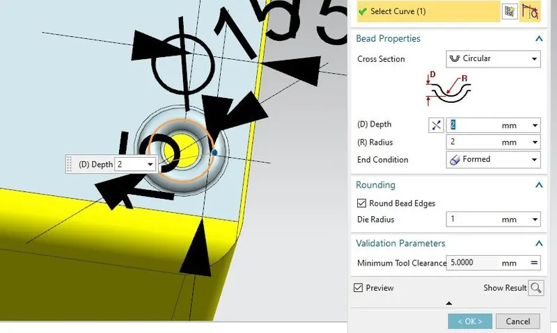
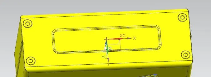
Draw a circle on the base of the box and add a bead on the base using the Bead feature.
Mirror the bead about the YZ and ZX planes.
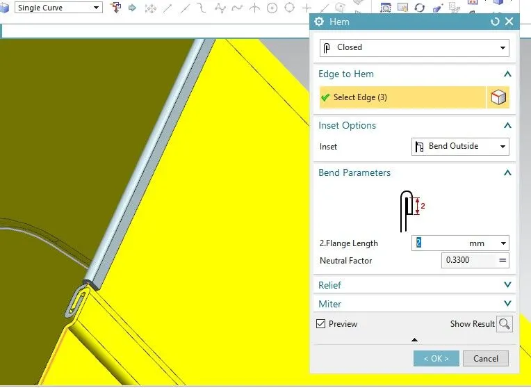
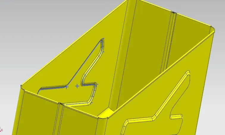
Use the Hem Flange to create the flange on the side walls.
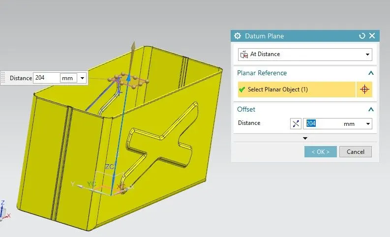
Create a new plane with an offset distance of 204mm from the XY plane.
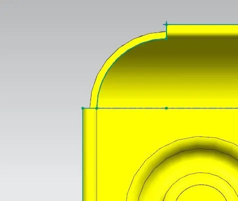
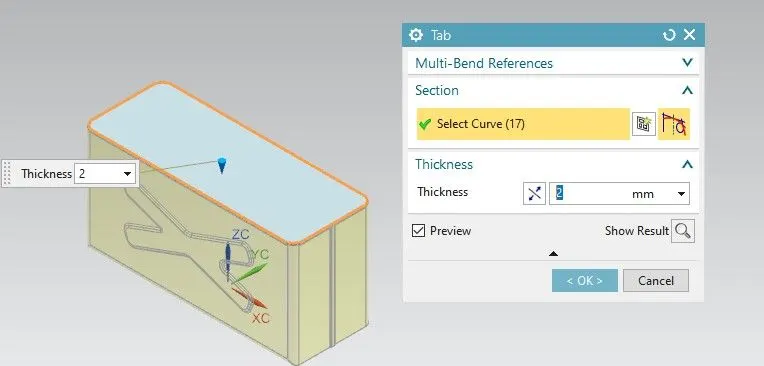
Draw the lid sketch and design the lid using the Tab feature.
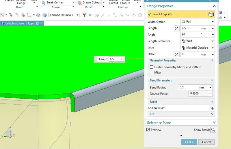
Create the flanges on the lid sides.
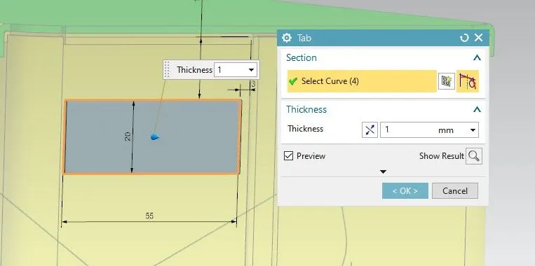
Create the base of the hinge on the right side walls using the Tab feature.
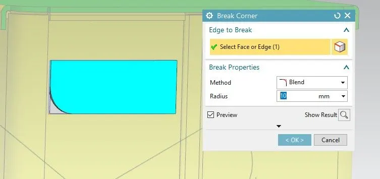
Use break corner and make the round corner of 10mm radius.
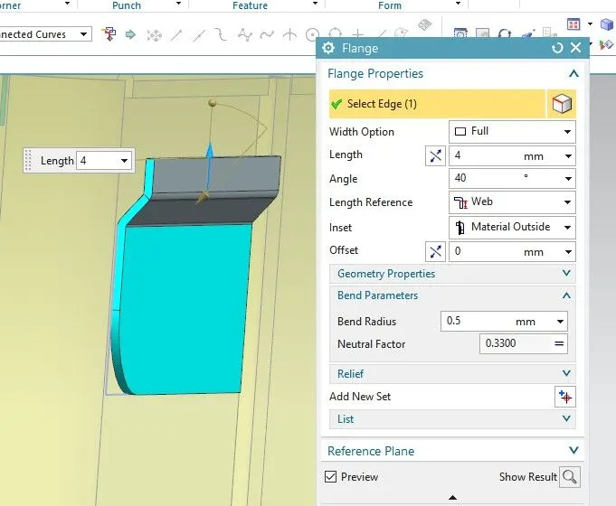
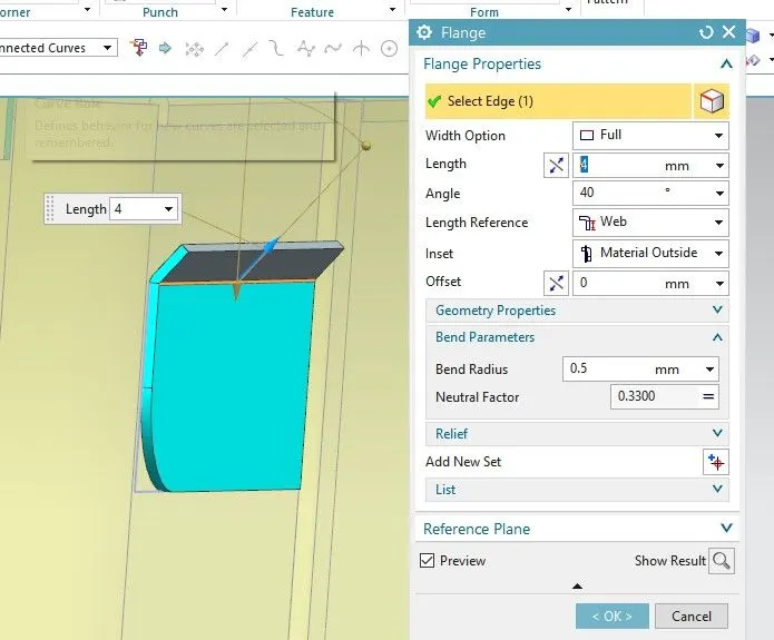
use the flange feature to create the flange of 4mm length at 40 degrees angle with 0.5mm bend radius.
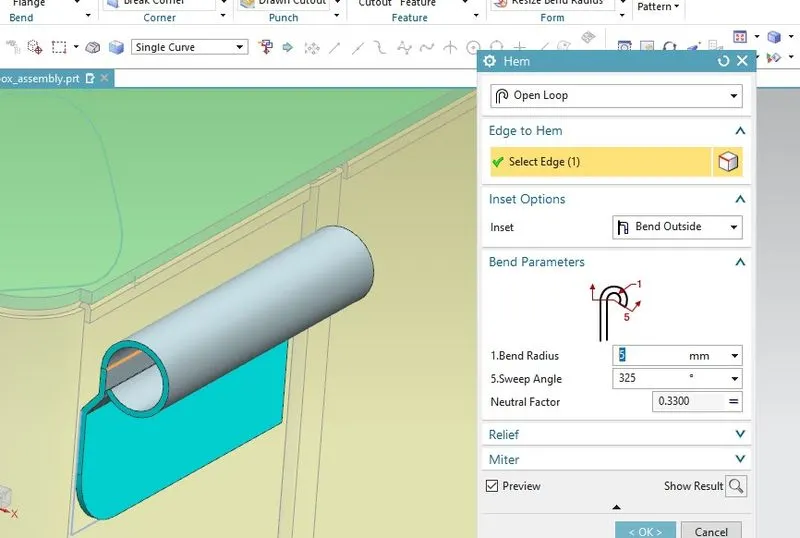
Use the hem flange and create the flange of 5mm bend radius with the 325 degrees sweep angle.
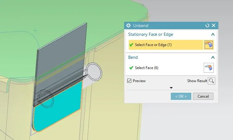
Unbend the design.
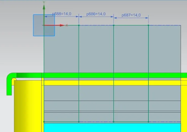
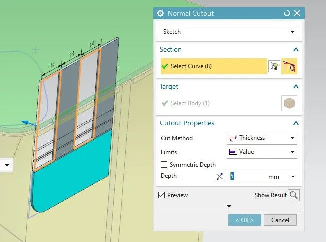
Draw the sketch and remove the unnecessary material using the Normal Cutout feature.
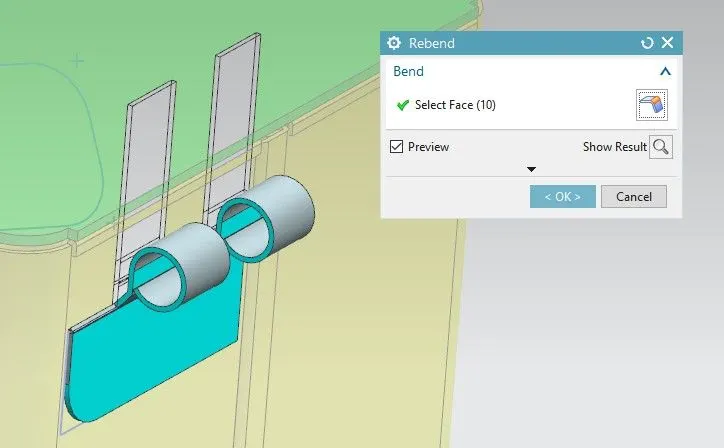
Rebend the design of the Hinge.
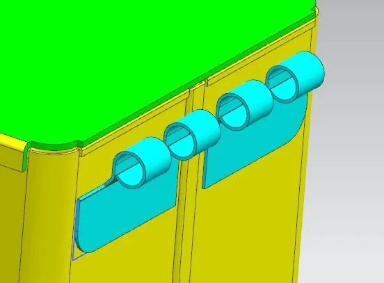
Mirror the Hinge.
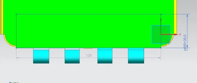
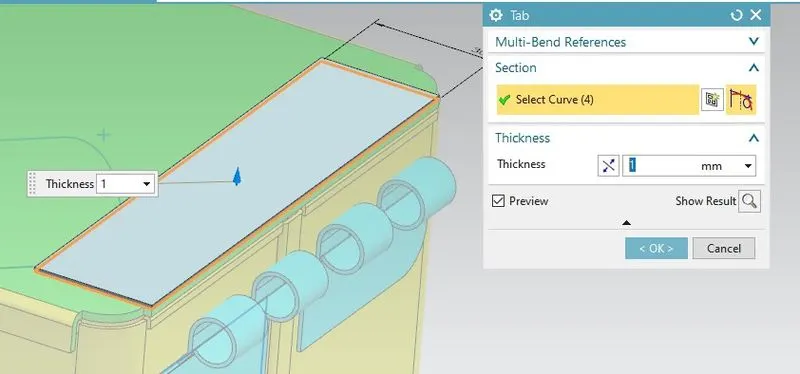
Create the sketch for another hinge and design the hinge based on the surface of the lid.
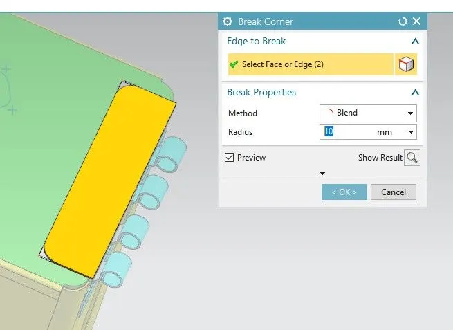
Use the Break Corner feature to make the round corners.
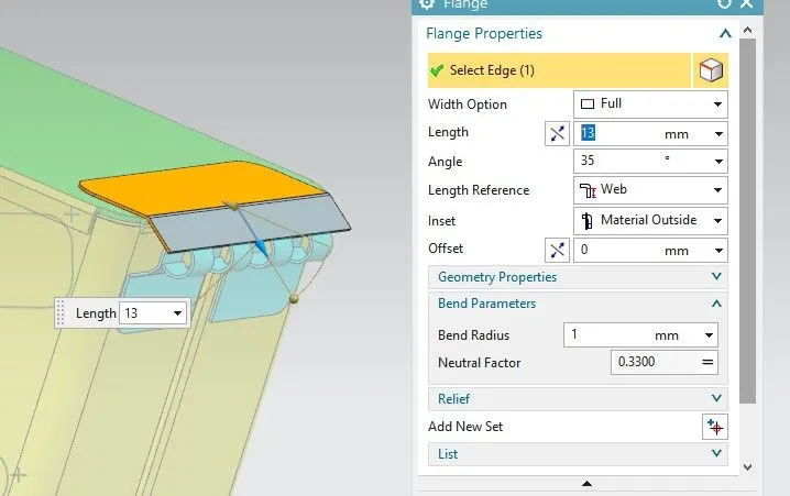
Use the Flange feature of 13mm length at 35 degrees angle with a bend radius of 1mm.
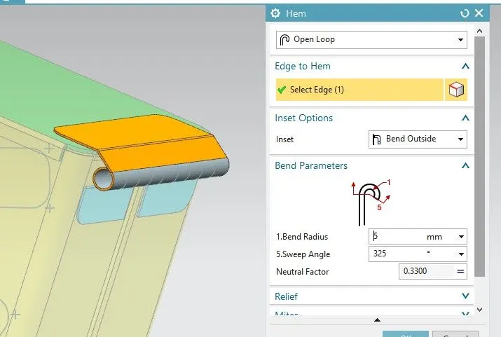
Use the Hem Flange feature of bend radius of 5mm with sweep angle of 325 degrees.
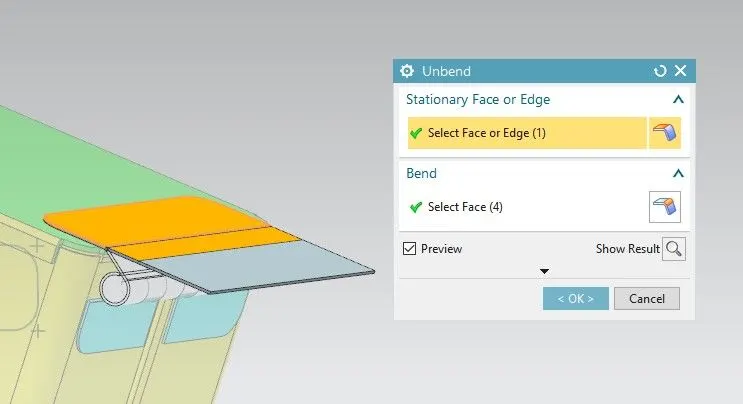
Unbend the design using the Unbend feature.
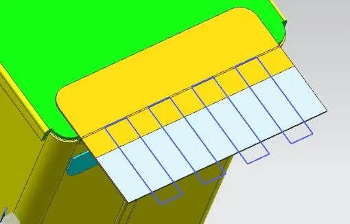
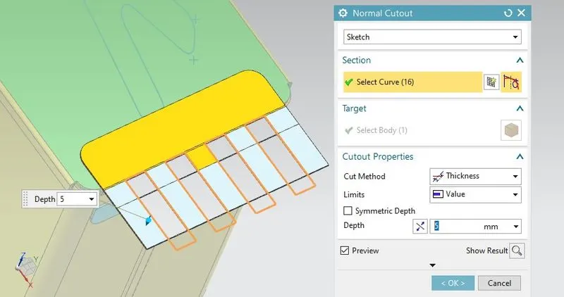
Create the sketch on the surface of the hinge and remove the unnecessary material using the Normal Cutout feature.
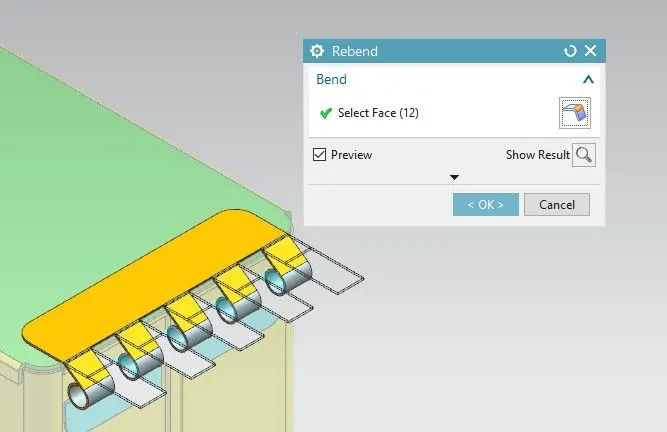
Unbend the hinge design.
View:
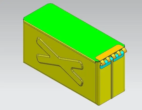
Isometric view:
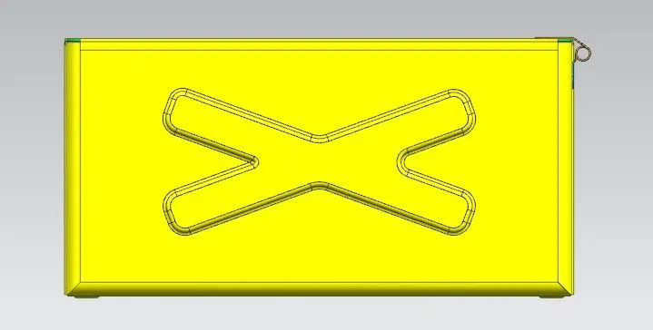
Front view:
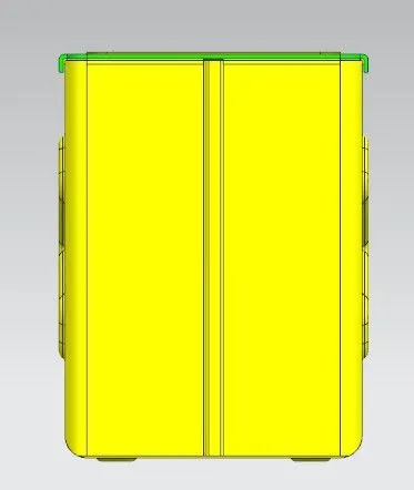
Side view:
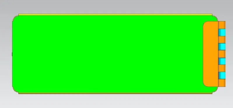
Top view:
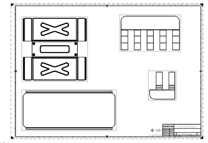
Drawing sheet of the Box Assembly:
Conclusion:
- Learn about the feature such as flange, tab, normal cutout, etc. in the design of Box Assembly using Siemens NX CAD.
- Learn about the standards of sheet metal used in industries.
- Creation of drawing sheet of box assembly using Siemens NX CAD.