Advanced Sheet Metal Design Using NX Cad Challenge_2_Box Assembly
The Title of the Project:
- Advanced sheet metal using NX CAD of Box Assembly is made with the proper method.
Objective:
- To create the Box assembly using sheet metal application of NX 12.
- We will learn about the features and tools used in this Design.
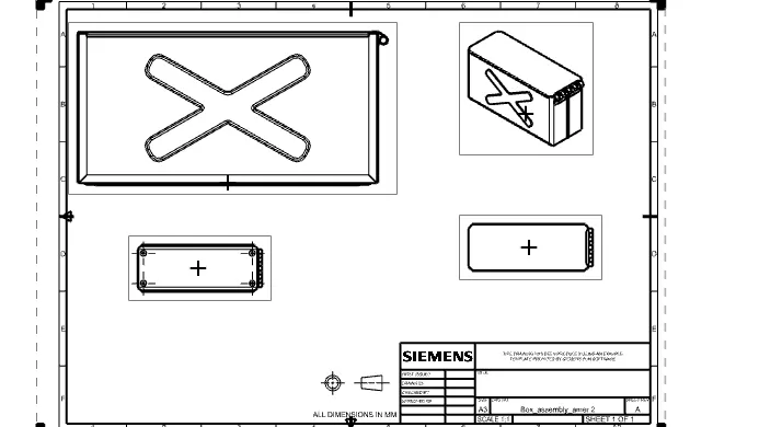
Introduction:
- Sheet metal formed by an industrial process into thin and flat pieces.
- Form guidelines for designing components using the two different manufacturing methods:
bending and pressing.
Investigate potential weight reduction using pressing rather than bending.
Investigate the potential usage of composite materials or the use of composite materials for
reinforcing metal.
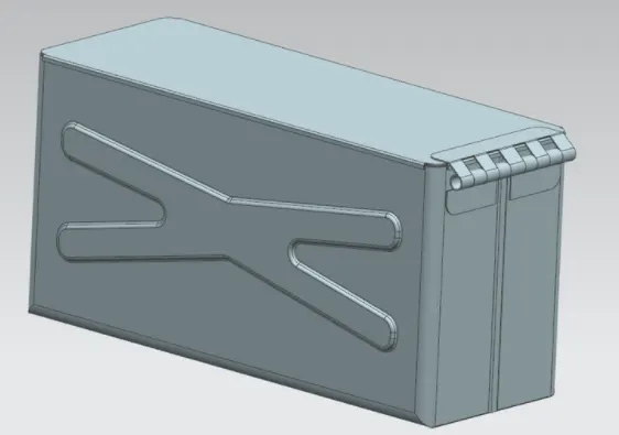
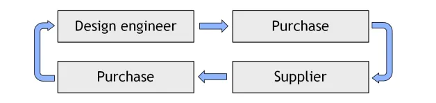
During the design of a new component, the design engineer's initial solution usually receives product
critiria from the supplier. This results in a lot of communication, both in and outside of the
company.
Design methodology of the Box Assembly.
1) Create the sketch and use the tab to make a strenght to it.
2) After the tab make the Flanges on it.
3) Use the Hem flanges and miorror the body.
4) Unbend the sheets, make a new sketches and rebend it.
5) Create a Dimple and Make a bead on it.
6) Create a drafting of the final model.
Features and tools used in the process are:
1) SKETCH: To create / drawing the geometries this is the basic tool we will used.
2) TAB : It is used to create the thickness of the sketched part of model.
3) FLANGES: This tool is used to create the bend regions of the sheet metal.
4) NORMAL CUTOUT: This tool is used to cut the selected cutouts to get the corners of it.
5) CLOSED CORNER: Its purpose is to closing the open edges of the sheetmetal application part of the component.
6) BEND AND UNBEND : This tool is used to bend and unbend the feature of the component for the required shape of the component.
7) MIRROR BODY: This feature is used to mirror the component of the body with respect to the selected planes.
8) HEM FLANGE: This tool is used to create the bend region of the compponent with angle and bend radius.
9) BREAK CORNER: This tool is used to create the sharp corners of the sheetmetal part application.
10) BEAD: Thia tool is used to create the punch on the surface of the sheetmetal part with respect to the basic sketch of it.
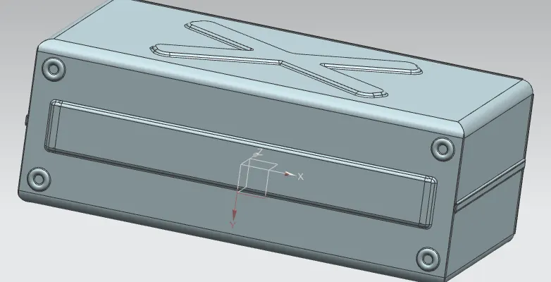
Creation of the dimple on both the sides if the component and beads formation to provide the strengthing to the component of sheetmetal part.
Mirror the component of all the beads formation to the edges of the sheet metal part component.
Bead formation.
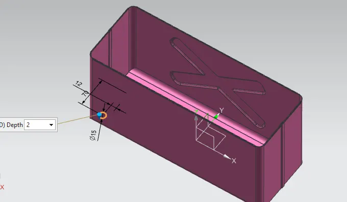
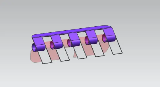
Hem formation.
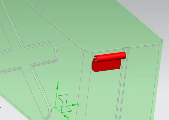
Normal Cutout fomation.
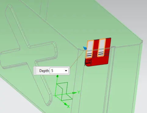
Tab and Hem formation.
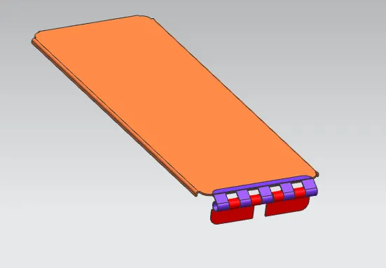
Unbend of Box assembly.
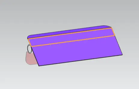
Rebend formation of the hem flanges.
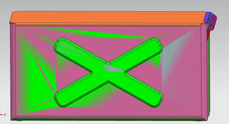
Different views of Box Assembly is shown in the below figures.
1)Trimetric view.
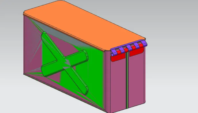
2) Left view.
3) Bottom view.
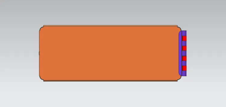
4) Top view.
Drafting of the Box Assembly.
Conclusion:
- Finally the Box Assembly is designed in Sheetmetal With the help of NX CAD 12.
- Got the knowledge of creating the different parts in the box assembly in sheet metal.
- Finally drafting the box assembly model with the proper method and mentioned in the format.