Advanced Sheet Metal Design Using NX Cad Challenge_2_Box Assembly
Title of the object: Box Assembly
Objective: To design a Box assembly using Siemens NX-CAD software.
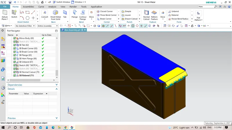
Introduction: In this project i have design a Box which is a sheet metal part by using NX-CAD software version 12.0.1 have explained all the tools and feature which are used in this sheet metal part modeling such as Tab, Flange, Dimple, Bend, Bead, Hem flange, Unbend, Rebend and Normal cutout etc.
Design Methodology of Box:
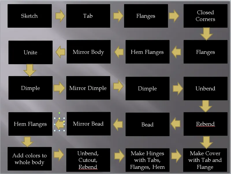
- Creation of rectangle of dimension 200X150 in XY plane and thickness of sheet metal is 1mm using Tab command.
- Creation of side flange of length 200mm and 90 degree with bend radius 10mm as well as another flange of length 70mm and 90 degree with bend radius 10mm.
- Modification of upper edge by using the Hem feature.
- Creation of Lock type using features like Tab, Brake, Corners, Hem and Mirror Features.
- Take a new plane at a distance 202mm from the datum plane for generateb a close top by using the feature Tab of thickness 1mm.
- Making a close surface by using feature closed corner both side.
- To give the particular shape with different dimensions by using Flange command.
- Creation of X type extrusion in both side using Dimple command and simple feature on bottom suface as well.
- Rebend the buttom portion by using the feature Rebend.
- Addition of some punch feature by using feature Unbend.
- Creation of 4 beads depth of 2mm and radius 2mm by using bead around the four corner on the bottom surface.
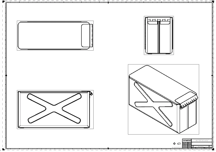
Different views of the model:
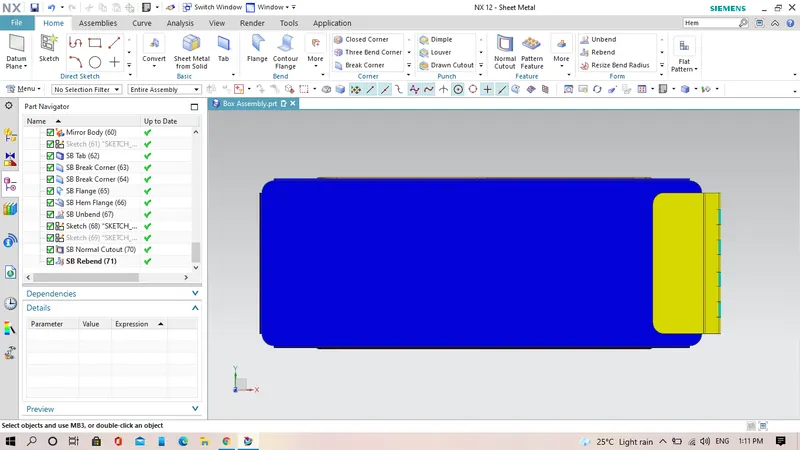
Top view:
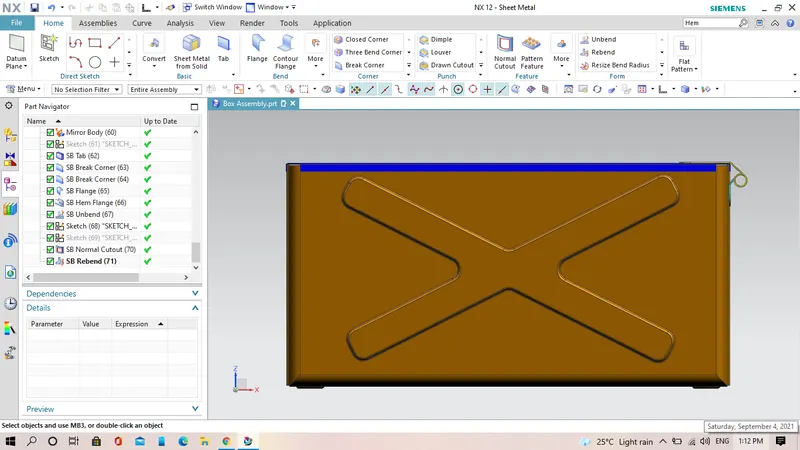
Front View:
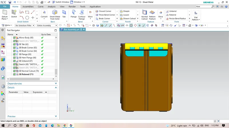
Right View:
Isometric View:
Drawing Sheet:
Conclusion:
In this challenge, i have completed the Box assembly use some features like Tab, Dimple, Brake Corner, Mirror body, Mirror Feature, Hem, Normal cutout and so on.