MODELLING OF SHEET METAL CASING
Project Report on Design of Sheet metal Casing
Title :
Design of sheet metal casing
Objective :
To design 3D model of sheet metal casing using NX 12
Introduction :
Sheet metal is metal formed by an industrial process into thin, flat pieces. Sheet metal is one of the fundamental forms used in metalworking, and it can be cut and bent into a variety of shapes. Countless everyday objects are fabricated from sheet metal. Sheet metal casing is a cabinet for electrical or electronic equipment to mount switches, knobs and displays and to prevent electric shock to equipment user. It is also used to protech the equipment from environment. It may be designed not only for its utilitarian requirements, but also to be pleasing to the eye. Sheet metal casing/enclosures are usually made from rigid plastics, or metals such as steel, stainless steel, or aluminum. Polycarbonate, glass-reinforced, and fiberglass boxes are used where stronger cabinets are required, and may additionally have a gasket to exclude dust and moisture.
Design Methodology
Description :
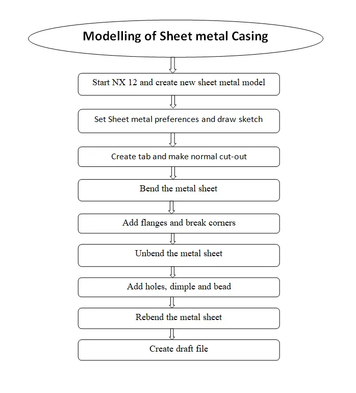
Various steps performed while designing the model are explained in detail as follows
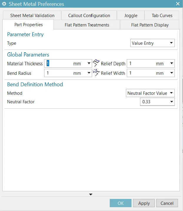
1. SHEET METAL PREFERNCES
Set the sheet metal preferences as shown below
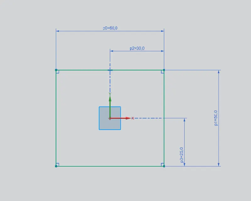
2. SKETCH
Select XY plane and draw the sketch using given dimensions
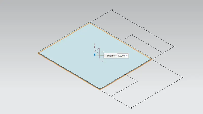
3. TAB
Create tab using the sketch
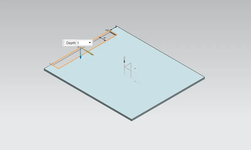
4. NORMAL CUTOUT
Make a rectangular cutout using normal cutout feature
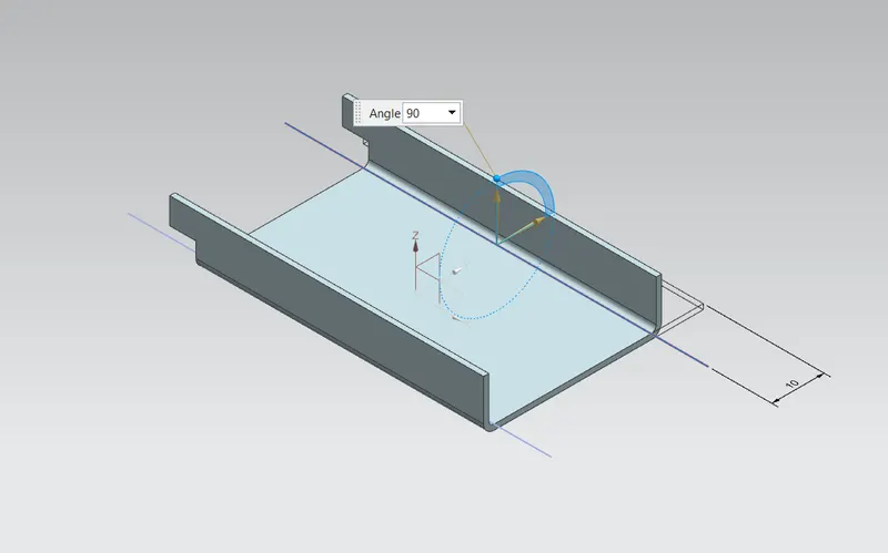
5. BENDING SHEET METAL
Bend the sheet metal as per given requirements
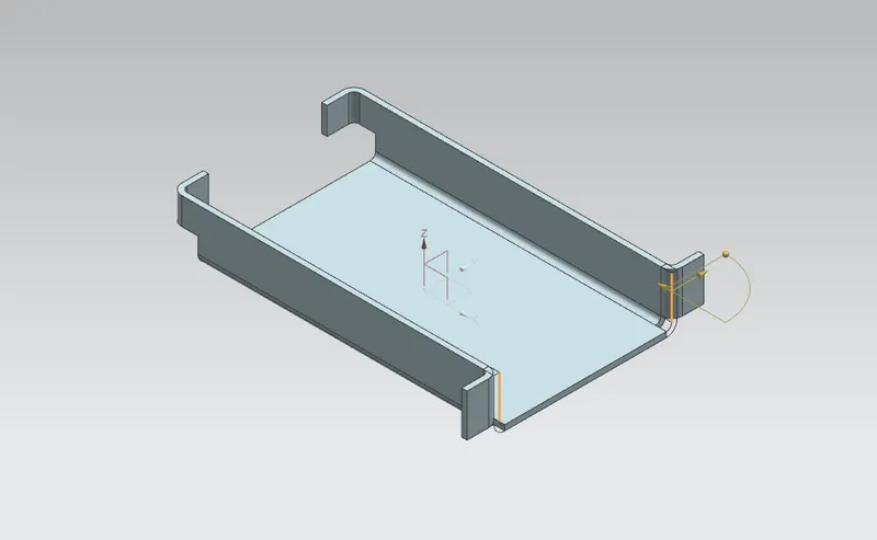
6. ADDING FLANGES
Use flange command and add flanges at four corner edges
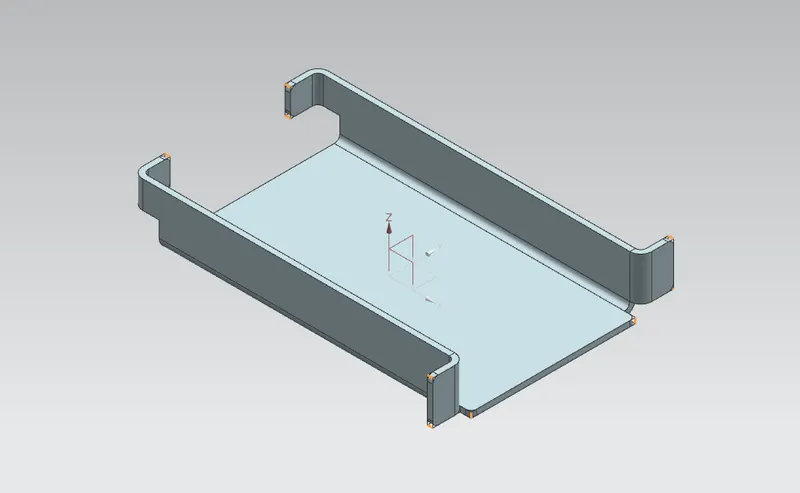
7. BREAKING CORNERS
Use break corner command to convert the edges as shown
8. UNBENDING SHEET METAL
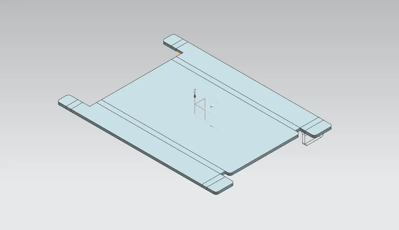
Use unbend command to unbend the sheet metal to add more features
9. ADDING HOLES
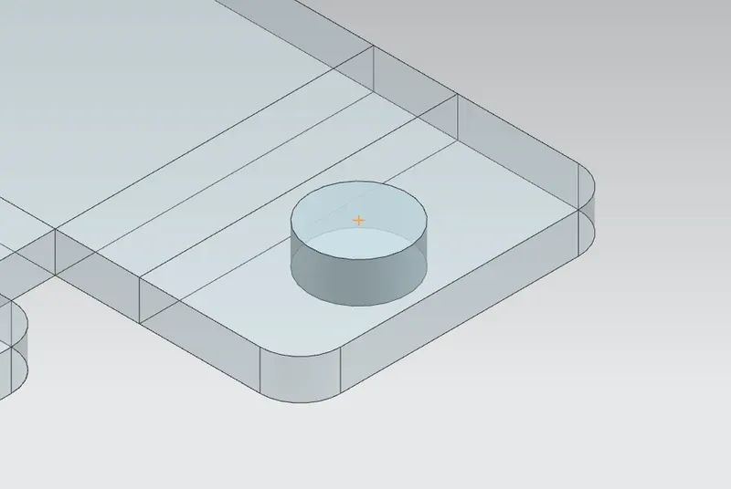
Add holes as per given dimensions and use mirror feature to mirror the holes
10. ADDING A DIMPLE
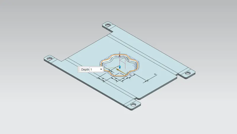
Create new plane on the surface and add dimple at the centre
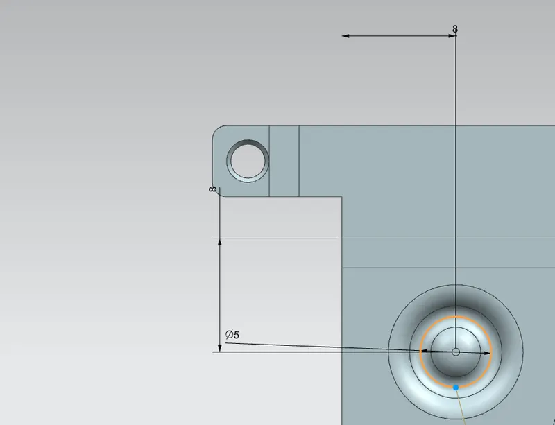
11. ADDING BEADS
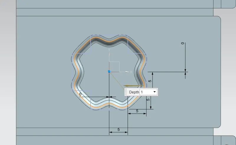
Add beads as per given dimensions
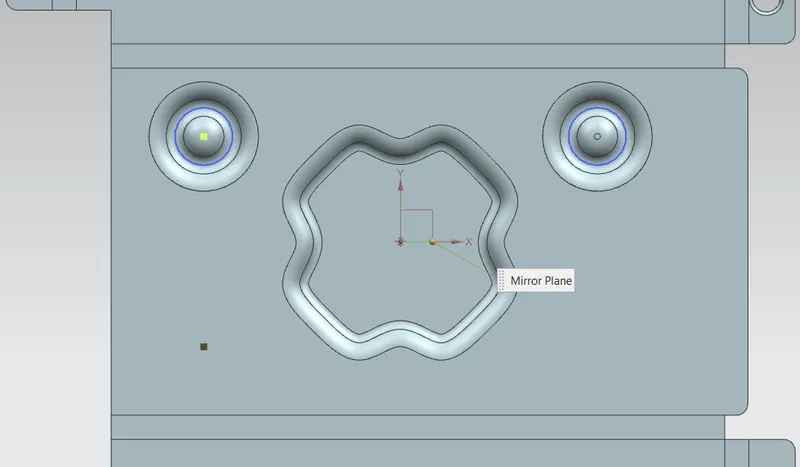
12. MIRROR FEATURE
Use mirror feature to mirror beads
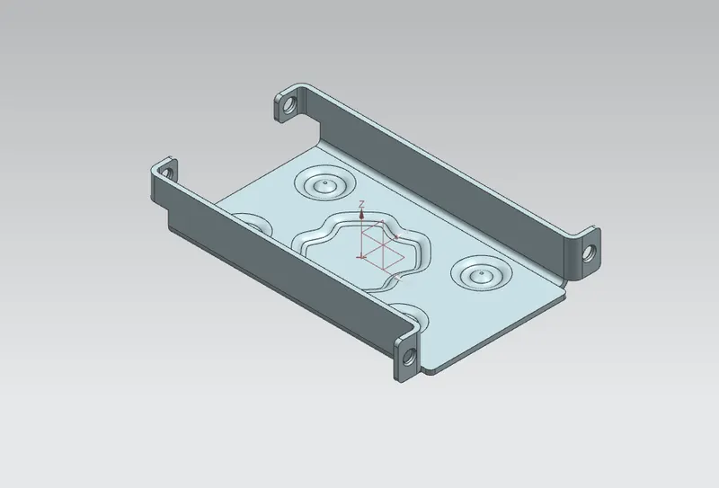
13. REBENDING SHEET METAL
Rebend the sheet metal using Rebend command. Follow the same steps you followed while unbending
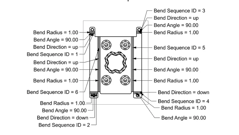
14. FLAT PATTERN
Create flat pattern using flat pattern command
15. DRAFTING
Create draft file on A4 sheet
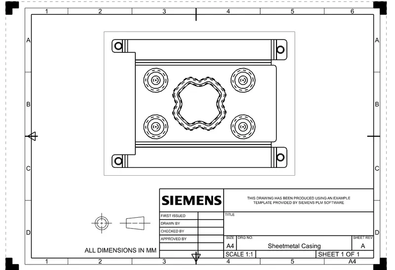
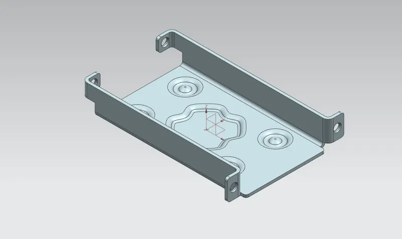
MODEL STANDARD VIEWS
ISOMETRIC VIEW
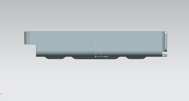
FRONT VIEW
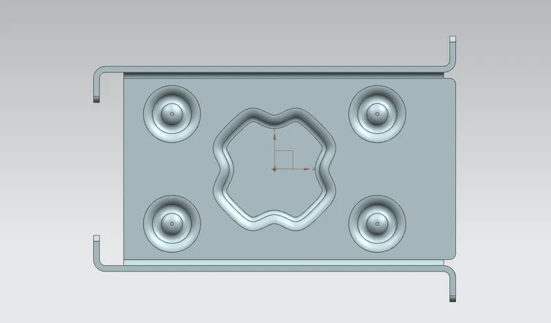
TOP VIEW
BACK SIDE VIEW
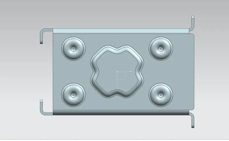
RIGHT SIDE VIEW
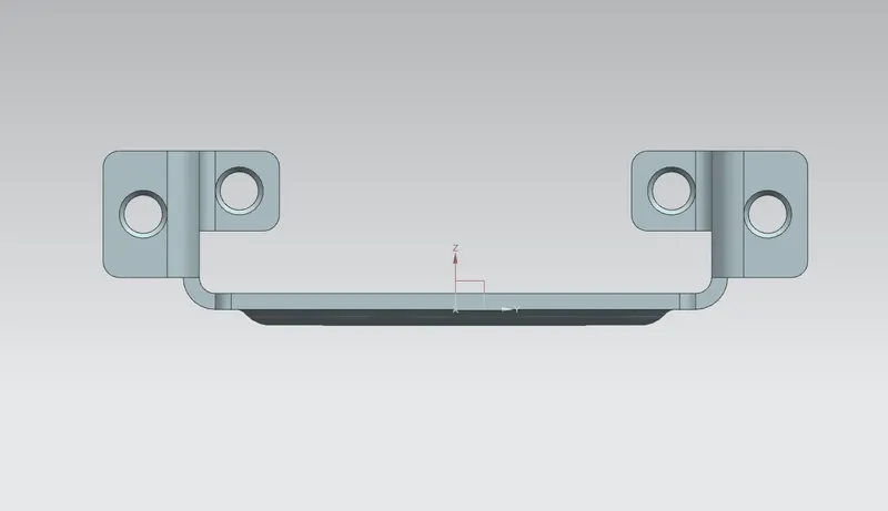
CONCLUSION
Modelling of Sheet metal casing is done successfully using NX 12
This is the link for the part file
https://drive.google.com/drive/folders/12DzIFtSv8zwnb4Z_4rktxAmOOUwv6qYt?usp=sharing
Thanks & Regards
Vishal Sutar