MODELLING OF AMERICAN CHOPPER BIKE
Title - Design and Assembly of American Chopper using SolidWorks
Objective - To design various parts of American Chopper, performing assembly and photorealistic rendering
Introduction - Here we will discuss steps to design various parts of American chopper using SolidWorks. Also we will perform assembly of these parts and do photorealistic rendering of part files and assembly file.
Design Methodology
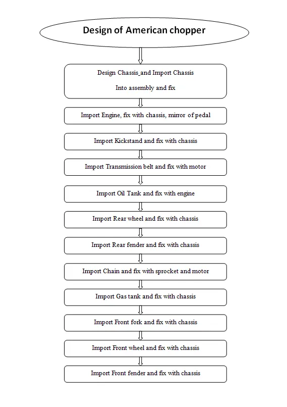
Description -
In this project we will design following parts :
- Transmission Belt
- Kickstand
- Front Fender
- Rear fender
- Oil tank
- Stand/Pedal
- Chain
- Front wheel
- Rear wheel
- Front fork
- Chassis
- Engine
- Gas Tank
Let's discuss how to design these parts in detail.
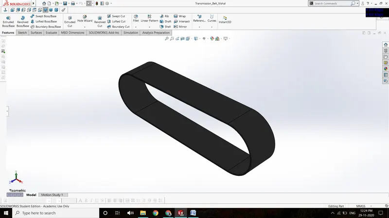
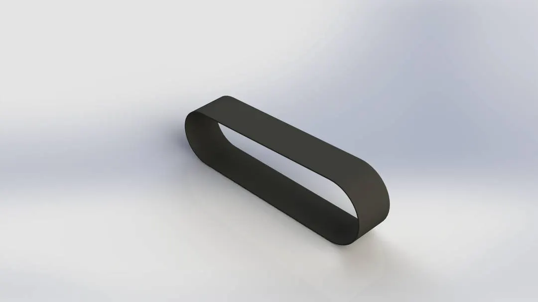
1. Transmission Belt
Transmission belt is used as power transmitting medium, which gives power from the engine to rear wheel axle, which lets it to move. In this part, it contains various features as:
Boss extrude – used to extrude the 2D sketch up to a limited height.
Fillet – used to give round shapes to corner & edges.
Part images :
Rendered images :
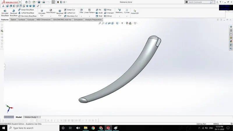
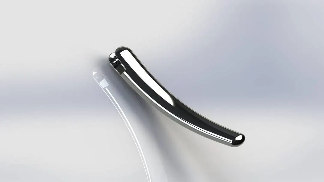
2. Kickstand :
It is a support of the bodyweight of the motorcycle, which rests on the ground at an angle. In this part following commands are used:
Boss extrude – used to extrude the 2D sketch up to a limited height.
Cut extrude – used to form a hole or cut the extruded part.
Fillet – used to give round shapes to corner & edges.
Loft – used to create a solid loft, via two profile sketch drawn on different planes and selecting a path curve as a guide.
Split – used to cut the solid part via selecting the intersecting part as a trim tool.
Dome - used to give a dome shame over a plane face.
Part images
Rendered images :
3. Front fender
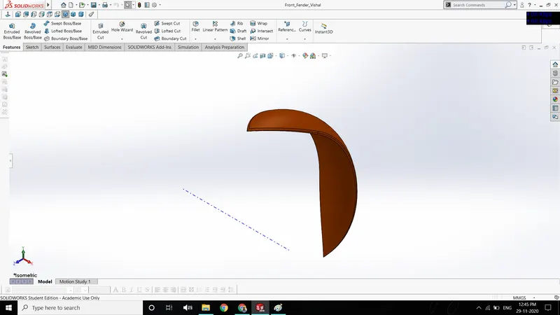
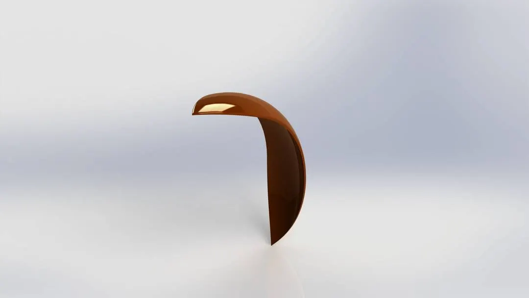
In this part, the following command features are used:
Revolve – used to create a revolve shape by giving one of the lines as a central axis about which the sketch is to be revolved.
Split – used to cut the solid part via selecting the intersecting part as a trim tool.
Fillet – used to give round shapes to corner & edges.
Part images
Rendered images :
4. Rear fender
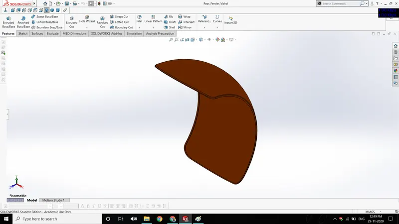
In this part, the following command features are used:
Revolve – used to create a revolve shape by giving one of the lines as a central axis about which the sketch is to be revolved.
Split – used to cut the solid part via selecting the intersecting part as a trim tool.
Fillet – used to give round shapes to corner & edges.
Part images
Rendered images :
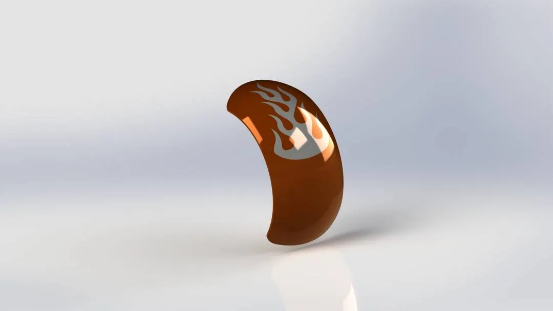
5. Oil tank
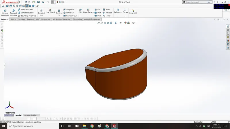
In this part following command features are used:
Boss extrude – used to extrude the 2D sketch up to a limited height.
Fillet – used to give round shapes to corner & edges.
Shell – used to give a hollow feature in the solid part with some thickness.
Split – used to cut the solid part via selecting the intersecting part as a trim tool.
Part images
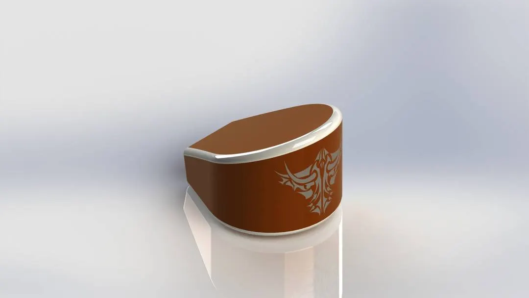
Rendered images :
6. Pedal
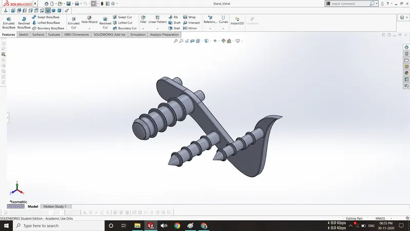
Pedal is used for placing the foot over it. It consists of the following features:
Boss extrude - used to extrude the 2D sketch up to a limited height.
Dome - used to give a dome shame over a plane face.
Revolve - used to create a revolve shape by giving one of the lines as a central axis about which the sketch is to be revolved.
Fillet - used to give a round shape to corner & edges.
Chamfer - used to give taper shape to corner & edges.
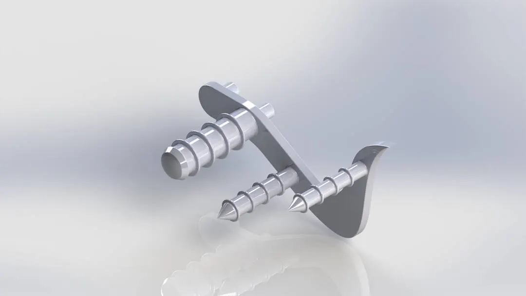
Linear pattern – used to pattern a feature along a linear path.
Part images
Rendered images :
7.Chain
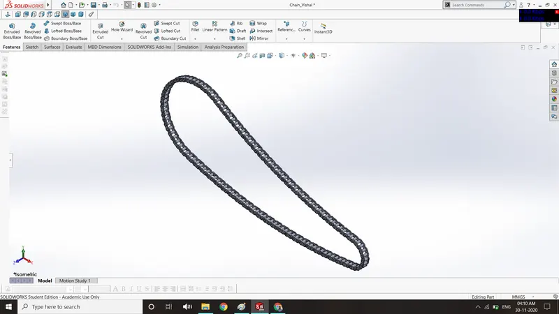
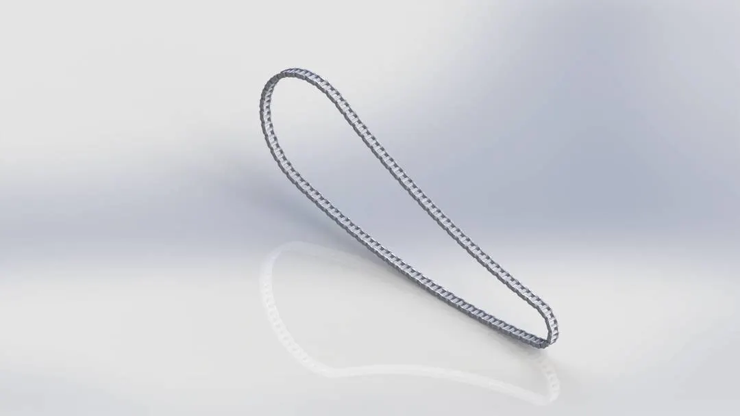
Chain is an end to end linkage connection of small link. In this part, a single sketch is used as a block to use it repeatedly over a defined path. In this part, the features used are as follows:
Boss extrude - used to extrude the 2D sketch up to a limited height.
Fillet – used to give round shapes to corner & edges.
Curve pattern – used to pattern a feature along a curve.
Mirror – used to create the half portion of a part on its opposite side by selecting a plane or face as a mirror face.
Part images
Rendered images :
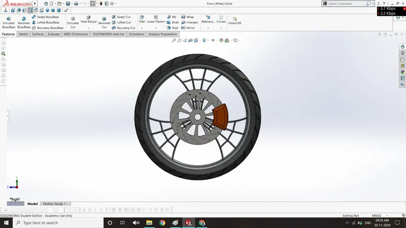
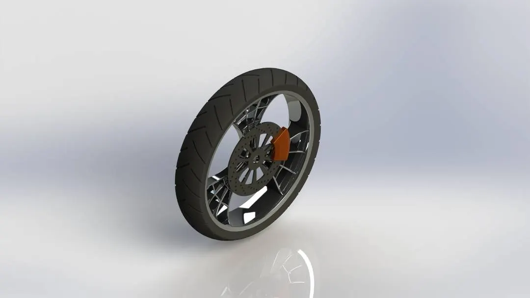
8. Front wheel
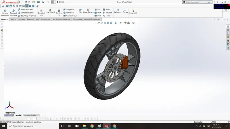
: In this part following command features are used:
Boss extrude – used to extrude the 2D sketch up to a limited height.
Cut extrude – used to form a hole or cut the extruded part.
Revolve – used to create a revolve shape by giving one of the lines as a central axis about which the sketch is to be revolved.
Cut revolve – used to cut the solid part in a revolving manner.
Combine – used to combine two solid part together.
Fillet – used to give round shapes to corner & edges.
Chamfer – used to give taper shapes to corner & edges.
Circular pattern – used to create a pattern in a circular path.
Part images
Rendered images :
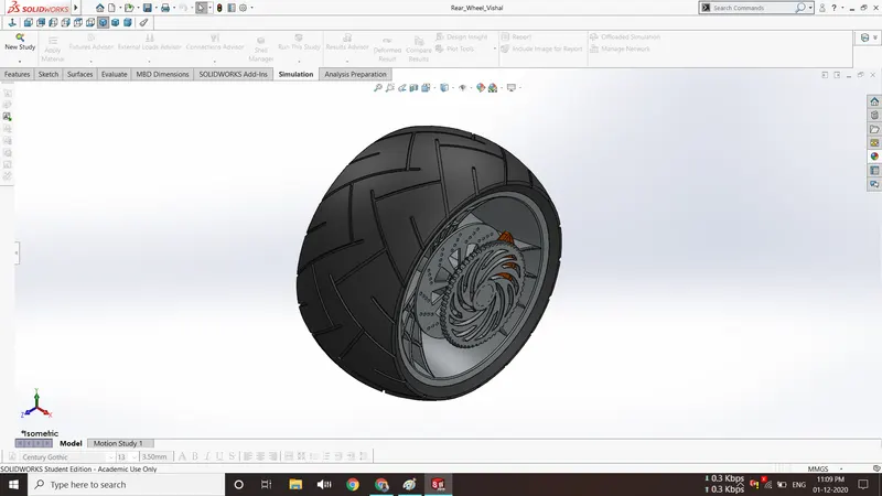
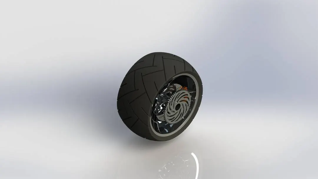
9. Rear wheel
In this part following command features are used:
Boss extrude – used to extrude the 2D sketch up to a limited height.
Cut extrude – used to form a hole or cut the extruded part.
Revolve – used to create a revolve shape by giving one of the lines as a central axis about which the sketch is to be revolved.
Cut revolve – used to cut the solid part in a revolving manner.
Combine – used to combine two solid part together.
Fillet – used to give round shapes to corner & edges.
Chamfer – used to give taper shapes to corner & edges.
Circular pattern – used to create a pattern in a circular path.
Part images
Rendered images :
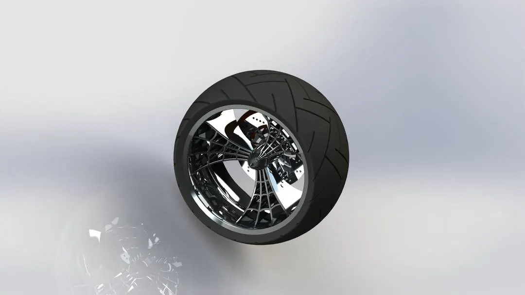
10. Front fork
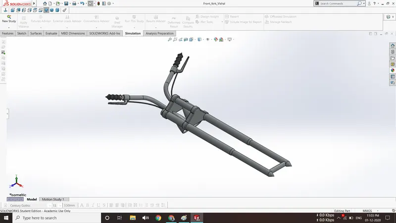
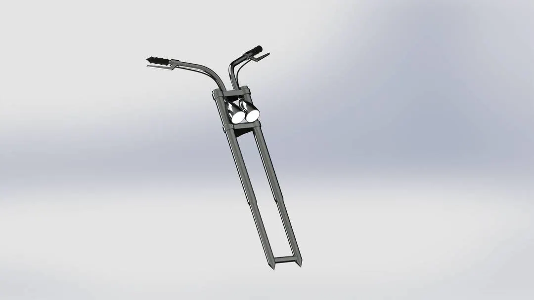
Front fork end gives angle direction to the front wheel. Its upper end consists of handle & lower end is connected to the front wheel, which helps in giving direction to the front wheel. In this part following command features are used:
Revolve – used to create a revolve shape by giving one of the lines as a central axis about which the sketch is to be revolved.
Boss extrude – used to extrude the 2D sketch up to a limited height.
Fillet – used to give round shapes to corner & edges.
Linear pattern – used to pattern a feature along a linear path.
Dome – used to give a dome shame over a plane face.
Cut revolve – used to cut the solid part in a revolving manner.
Sweep – used to sweep a profile sketch over a defined sketch path.
Combine – used to combine two solid part together.
Mirror – used to create the half portion of a part on its opposite side by selecting a plane or face as a mirror face.
Part images
Rendered images :
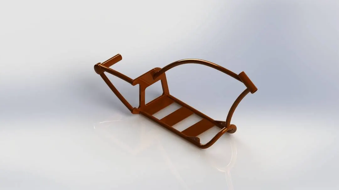
11. Chassis
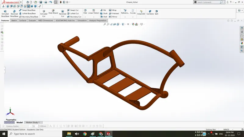
Chassis is the base part of all the motorcycles, through which all other individual parts such as the engine, front fork end, rear-wheel etc, are connected in it. In this part model of chassis, various features are used which are explained below as:
Curves – used to create complex shapes of chassis. it is created by the intersection of projecting curves or lines, sketched in a different plane.
Boss extrude – used to extrude the 2D sketch up to a required height.
Cut extrude – used to form a hole or cut the extruded part.
Fillet – used to give a round shape to corner & edges.
Chamfer – used to give taper shape to corner & edges
Sweep – used to sweep a profile sketch over a defined sketch path.
Split – used to cut the solid part via selecting the intersecting part as a trim tool.
Dome - used to give a dome shame over a plane face.
Revolve – used to create a revolve shape by giving one of the lines as a central axis about which the sketch is to be revolved.
Mirror – used to create the mirror image of a part by selecting a plane or face as a mirror face.
Part images
Rendered images :
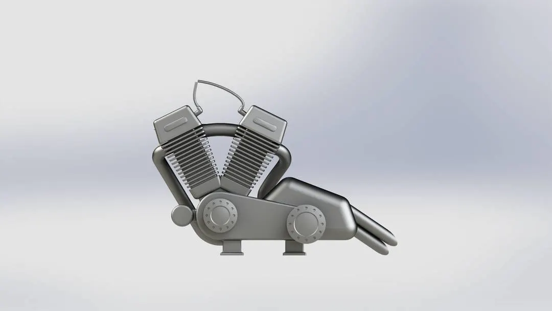
12. Engine
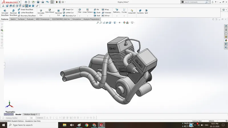
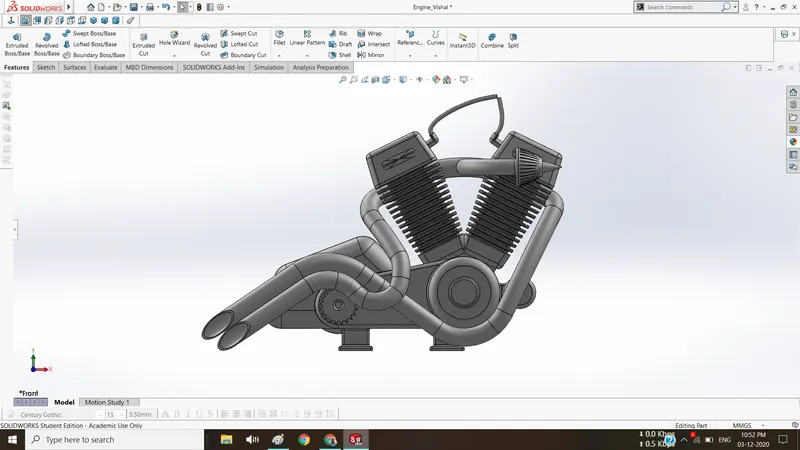
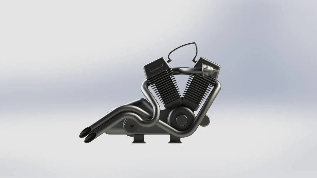
In this part following command features are used:
Boss extrude – used to extrude the 2D sketch up to a limited height.
Cut extrude – used to form a hole or cut the extruded part.
Revolve – used to create a revolve shape by giving one of the lines as a central axis about which the sketch is to be revolved.
Cut revolve – used to cut the solid part in a revolving manner.
Combine – used to combine two solid part together.
Fillet – used to give round shapes to corner & edges.
Chamfer – used to give taper shapes to corner & edges.
Circular pattern – used to create a pattern in a circular path.
Sweep – used to sweep a profile sketch over a defined sketch path.
Split – used to cut the solid part via selecting the intersecting part as a trim tool.
Dome - used to give a dome shame over a plane face.
Mirror – used to create the half portion of a part on its opposite side by selecting a plane or face as a mirror face.
Part images
Rendered images :
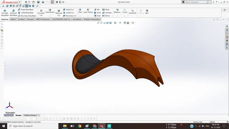
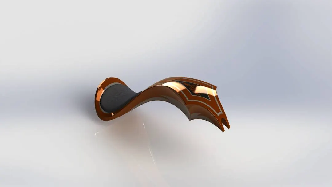
13. Gas tank
In this part following command features are used:
Curve – It is created by the intersection of projecting curves or lines, sketched in a different plane.
Surface sweep – used to create a surface using a profile sketch & path curve connected to it.
Surface loft – used to create a surface using two profile curves or edges & at least one guide curve.
Boundary surface – used to create a surface using boundary edges.
Surface knit – used to knit the two or more than two surfaces with each other, which can be identified by black line at their intersecting edges.
Cut sweep – used to cut the part using a profile sketch & a path along which the part is to be cut.
Shell – used to give a hollow feature in the solid part with some thickness.
Fillet – used to give round shapes to corner & edges.
Surface trim – used to trim the surface using a surface or line as a trim tool.
Mirror – used to create the half portion of a part on its opposite side by selecting a plane or
face as a mirror face.
Part images
Rendered images :
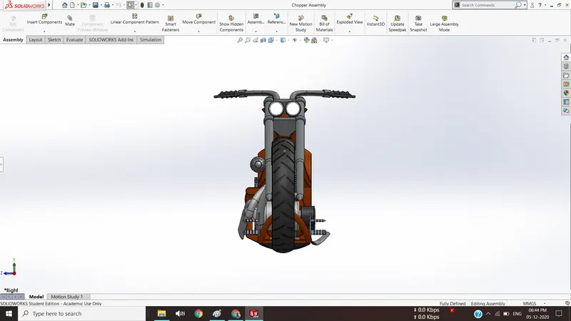
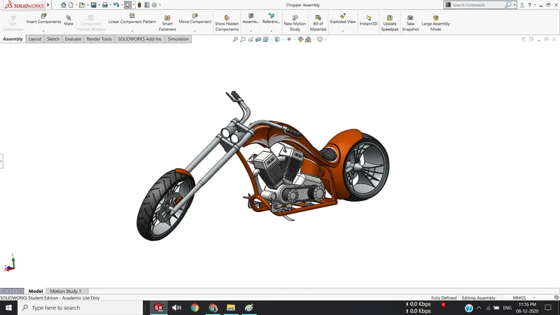
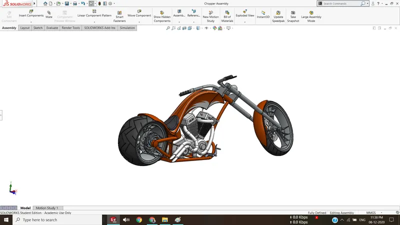
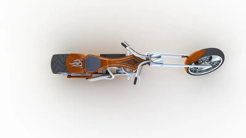
Assembly of american chopper :
In this section, all individual parts which are mentioned above are assembled together using various types of mates. These mates are defined below as:
Concentric mate – used to aline the parts along a single plane or direction.
Coincident mate – used to coincident the parts via their opposite faces.
Distance mate – used to place the parts at a defined distance from the fixed plane.
Limit angle mate – used to limit the angle of rotation of parts.
Width mate – used to place apart between two planes or faces with an accurate distance from the adjacent plane or face.
Parallel mate – used to place the parts parallelly, by selecting their same side face.
Decals: Decals are the logo, text & decorative design prints, which gives an attractive look to the parts. These decals are placed over the following parts:
- Gas tank
- Oil tank
- & Rear fender
Appearance: To give a better look to the parts, the colour appearance plays an important role which attracts everyone to focus on it. In this assembly model,
- orange colour is given to oil tank, gas tank, chassis, front fender & rear fender.
- Back colour containing rubber material property is given to the front & rear wheel tyres.
- White LED light colour effects is given to front headlight.
Assembly images
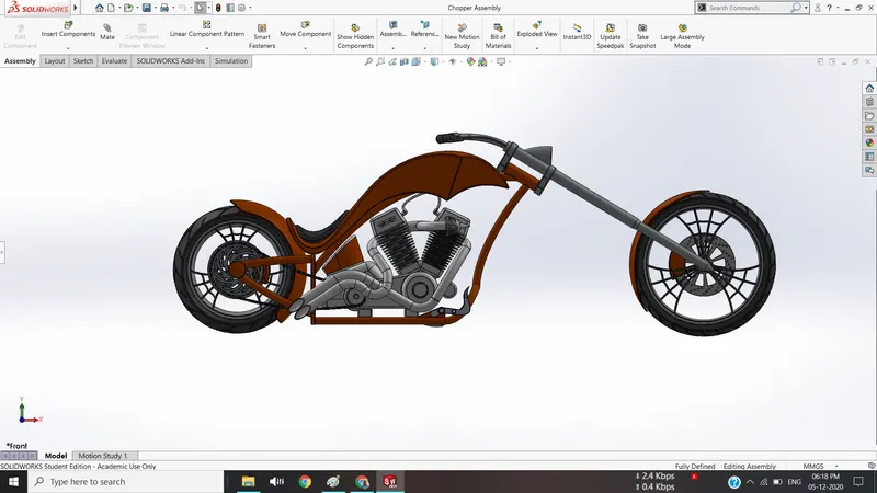
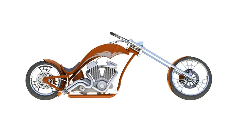
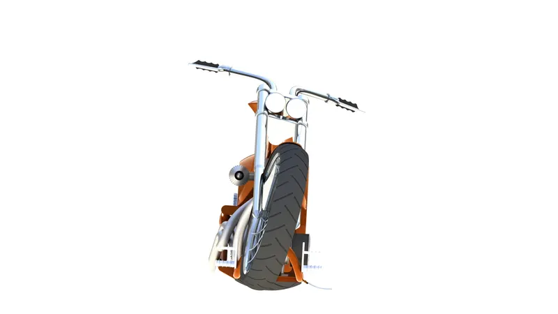
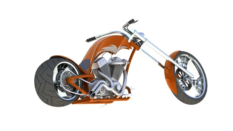
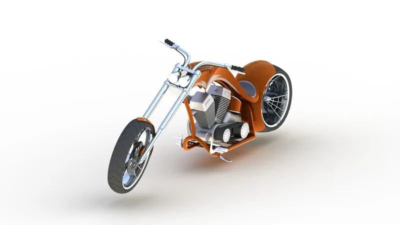
Rendering Images
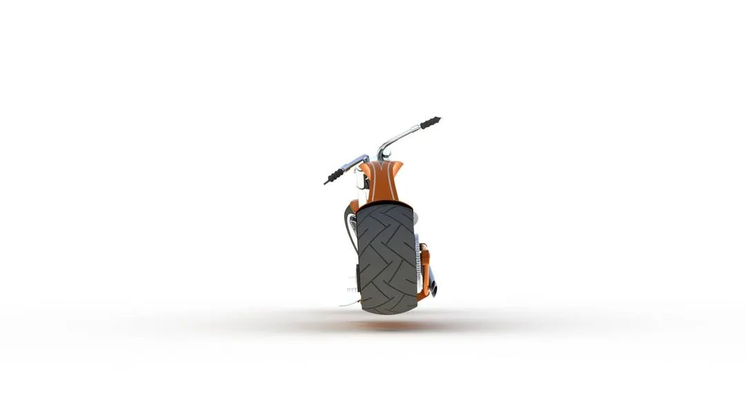
Solidworks Visualize
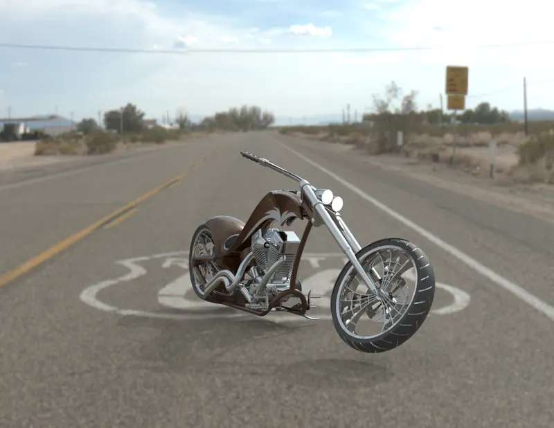
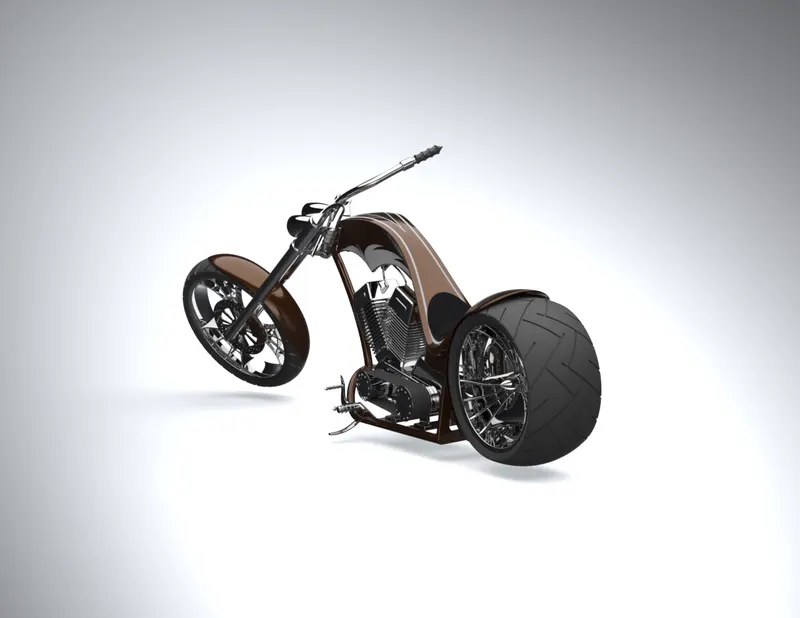
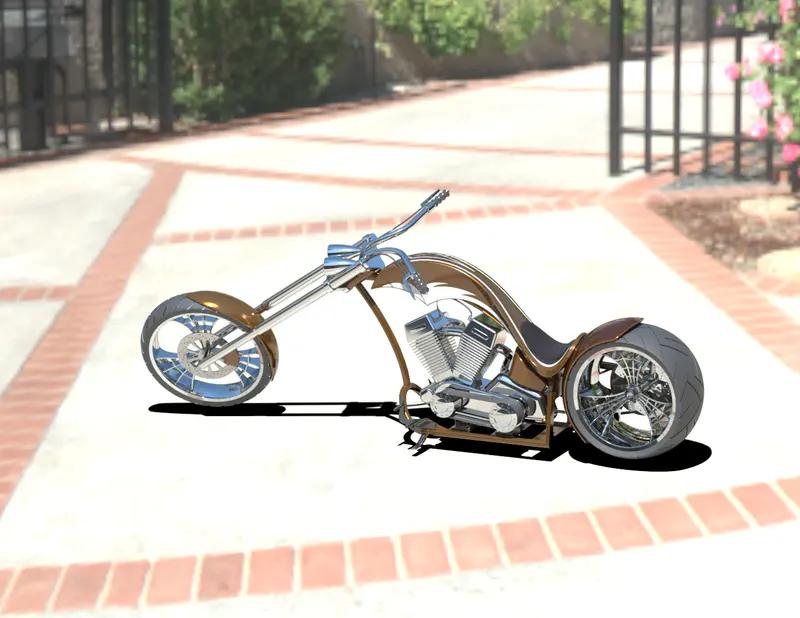
Conclusion : Modelling, Assembly and rendering of American chopper is done successfully using SolidWorks.
Link for zip file of all part files and assembly file :
https://drive.google.com/drive/folders/148PlkgU8SltPS8hVUxd8Wiwk7jE9Z_Hx?usp=sharing