Advanced Sheet Metal Design Using NX Cad -Casing Design
Title of project - Construction of caseing useing NX cad
Objectives - 1. get hold on nx cad tool
2 To get familiar with sheet metal operations in cad
Introduction
Sheet metal has wide applications in automotive and aerospace industries due to its high strenght and low weight and easy to manufacture .
sheet matals are generally catageriosed according to the thickness into gauges rangeing from gauge 07 to gauge 20
| Gauge | Thickness of steel sheet in mm |
|
07 |
4.547 |
| 08 | 4.191 |
| 09 | 3.810 |
| 10 | 3.429 |
| 11 | 3.048 |
| 12 | 2.667 |
| 13 | 2.286 |
| 14 | 1.905 |
| 15 | 1.702 |
| 16 | 1.524 |
| 17 | 1.372 |
| 18 | 1.1938 |
| 19 | 1.067 |
| 20 | 0.9144 |
Sheet metal terminology
Bend Radius
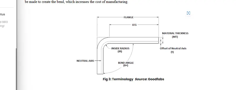
The sheet metals is benrt to a required angle by press brakes they do not formed the curve corners instead it will cause a curved corners . while designing we should use the standard bend radius.
K-Factor -
when the material is bent the inner portion undergoes compression and the outer portion gets stretched that means the inner length of the bent material decrease and the outer length of material increases . in between there is a line called as neutral line where there is no change in length
the ratio of neutral line distance to the material thickness is called as K-Factor . it depends upon material properties , material thickness, and bend radius
Bend allowance
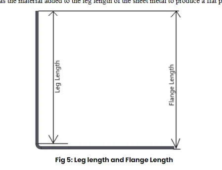
the bend allowance is added to the leg length of the sheet metal to produce a flat pattern
 .
.
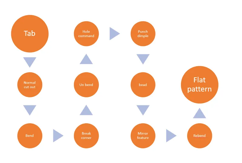
FLow chart
Tools and features used while designing
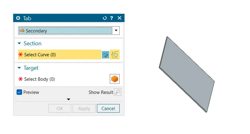
1.Tab-It creates the base sheet metal of required six=ze and thickness
2.Normal cut out- it cuts the sheet metal as per the sketch
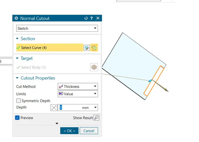
3.Bend - this tool bends the sheet metal with respect to chosen axis
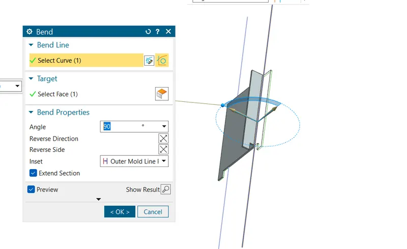
4.Break corner - This tool removes the sharp corners from component we have to provide the bend radius in this case
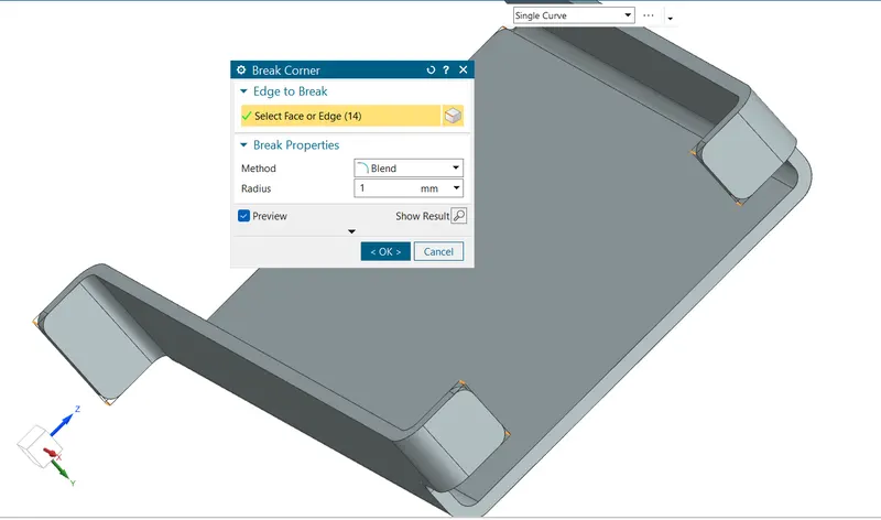
5.Unbend - this tool is used to make flatb sheet from a component we havt to choose a stationary face .
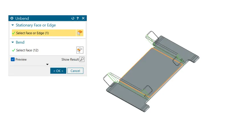
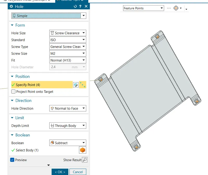
6.Hole command - this command helps us to create a hole as per requirement .in this command we have to choose the screw type hole size ,points ,hole direction and depth limit of hole
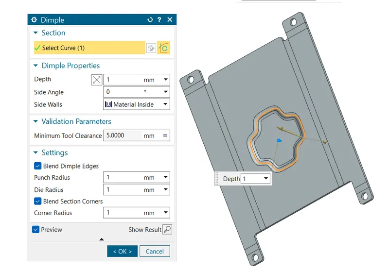
7. Punch dimple - this commands used to create the emboss like surfaces to sheet , we have to create a sketch and provided depth for the dimple also we have to provide the corner radius
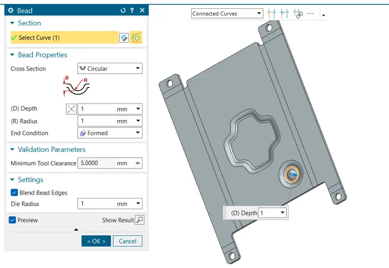
.8) Bead.- in order to improve the stiffness of the sheeet metal component beads are provided .
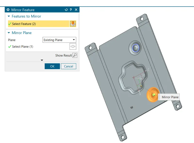
9. Mirrior feature - it is used to mirror the feature with refrence to plane. we have to select the sketch along with the feature to mirrior it
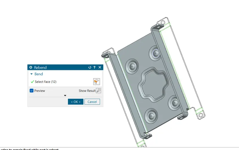
10. Rebend - it removes the unbend operation .
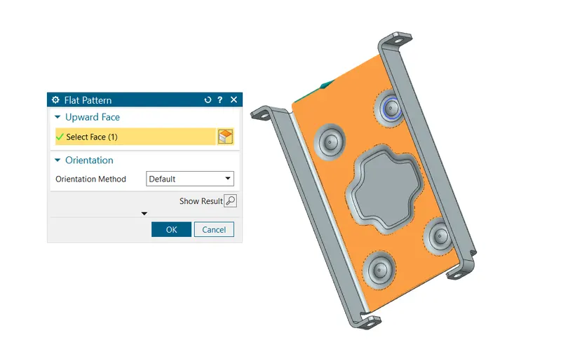
11.Flat pattern- In order to make all operations visible we have to use flat pattern
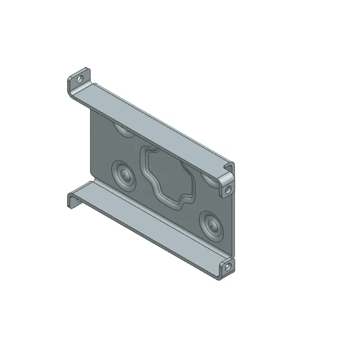
Isometric view
top view
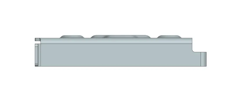
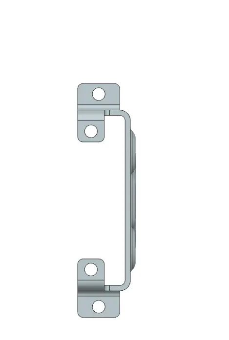
front view
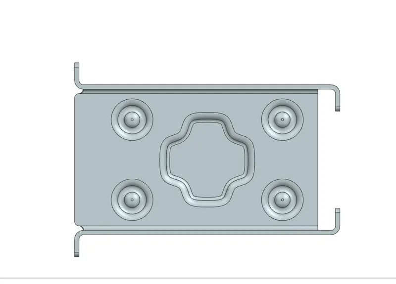
RHSV
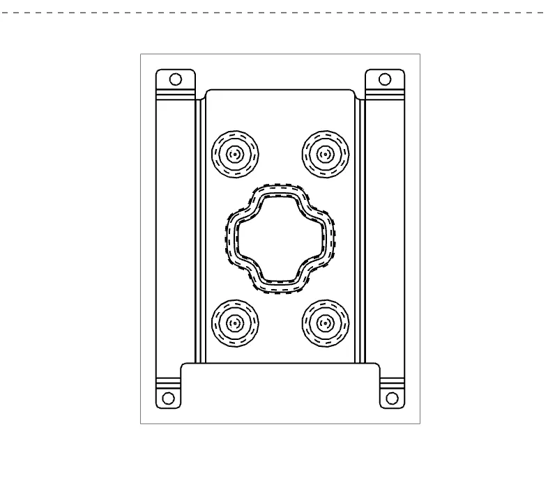
Drawing sheet
Conclusion -
In this way we have we have used the nx cad for creating the caseing and got familiar with the sheet metal operations