Advanced Sheet Metal Design Using NX Cad Challenge_1_Casing Design
CASING DESIGN
OBJECTIVE-
Create a Casing design model following the given guidelines by using NX Sheet metal application.
https://drive.google.com/open?id=1iFGcicuUq7InjqHUS9Eub5QXL7nwYrOy
INTRODUCTION-
Casing may refer to an enclosing shell, tube or surrounding material. it may also refer as
- Casing borehole, metal tube used during the drilling of a well.
- Casing molding, decorative molding surrounding door or window openings
- Casing sausage, thin covering holding the food contents of sausage.
DESIGN METHODOLOGY-
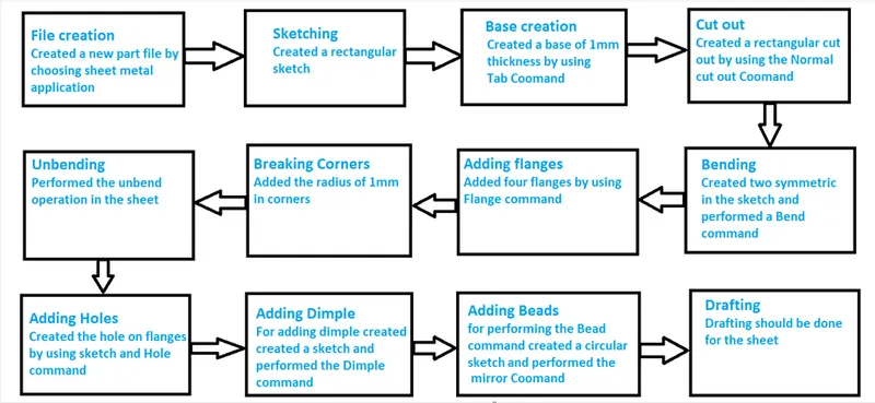
DESCRIPTION-
- SKETCH: This is used to create a basic sketch of the design on selecting the desired plane, then later it can be modeled for the requirement.
- TAB: This feature is used to create a base tab on selecting the curve drawn in sketch mode with the appropriate thickness on our desire and it can easily convert that sketch into the sheet.
- NORMAL CUTOUT: This feature is used to cut the portions of the sheet metal by assigning sketch curves.
- BEND: This feature is used to bend the sheet metal along the sketched curve upon our requirement.
- FLANGE: Flange is used to add flanges on selecting the edges of our sheet metal, it is working as a BEND feature along with that extra material can be added by adjusting the length of the flange.
- BREAK CORNERS: Break corners are used to make the edges round for easy handling when using.
- UNBEND: Unbend is a feature used to analyze the model whether a part was perfectly assigned the features, which ensures for a modeler to do further operations on it.
- HOLE: It is actually used for making the holes on the requirement for further assembly of the part by assigning different types of specifications of screws.
- DIMPLE: It is used to draw a dimple on selecting a curve for modelling the sheet.
- BEADS: This feature is used to create a bead on the sheet which generally strengthens it.
- MIRROR: It is used to add the material or feature replicates by acting as a mirror to it, this generally reduces the modeling time.
- REBEND: This is used to re-bend the object after all conformations and ready for production.
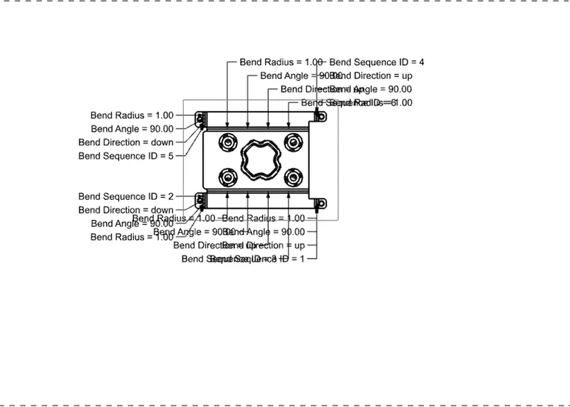
- DRAFTING: It is used to provide the dimensions and views of the designed part to the manufacturing team.
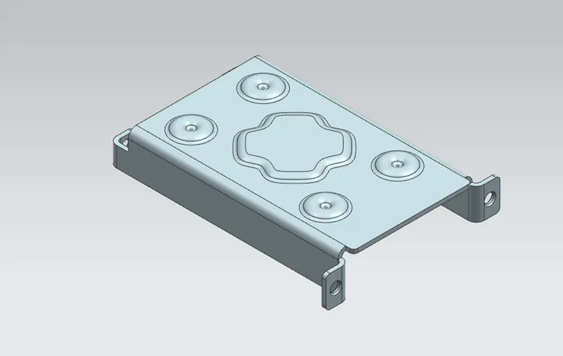
Different views of model-
- Isometric view-
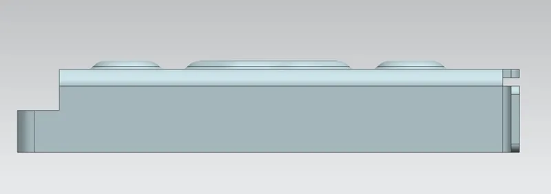
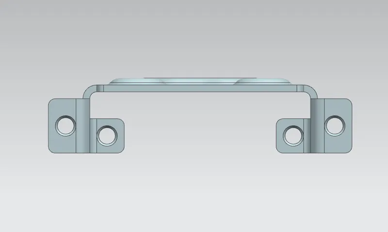
- Front view-
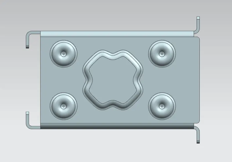
- Top view-
- Side view-
DRAWING SHEET-
CONCLUSION-
In this challenge we created the sheet metal casing Design using given guidelines. We learn about the various commands in NX Sheet metal application.