Advanced Sheet Metal Design Using NX Cad Challenge_1_Casing Design
CASING DESIGN AND DRAFTING USING SIEMENS NX CAD
Objective
The aim of the project is to design the casing by following the industrial design methodologies applied for manufacturing a sheet metal component and do a draft drawing for the casing.
Introduction
Sheet metal is any metal that has a thickness in between 0.4 to 6 mm and it can be obtained by any metal rolling process method (cold rolled and hot rolled). Sheet metal widely used in industries like automobile, aerospace, electronic appliance, medical, construction, furniture, etc. To utilize sheet metal to its full extent we must understand standard measurements, materials, differences in manufacturing, possible forming methods and the material properties.
Sheet metal fabrication is the process of forming metal sheets to the desired shape using different manufacturing methods. The completion of a product usually comprises of many steps – from cutting and bending to surface treatment and assembling. Some of the manufacturing methods on sheet metals can be classified as follows:
- Cutting and Shearing- Shearing or die cutting, refers to a process that cuts sheet metal without burning or melting it. Also, it does not produce any chips. In shearing, a punch presses the work piece against a fixed die or blade. The clearance between is such that the work piece does not fit through, causing it to shear. Blanking, piercing, perforation, notching etc. are various types of shearing operations.
- Bending Operation- Bending is a forming process in which sheet metal is bent into the desired shape by applying bending stress and plastically deformed into the desired shape. That plastic deformation of bend sheet prevents the metal from regaining its former shape.
- Forming-Sheet metal is reshaped into the useful shape by means of some mechanical action. Shearing a, cutting and bending are some of the forming operations.
- Drawing Operations- Drawing process is a forming process which occurs under a combination of tensile and compressive conditions. A flat sheet metal blank is formed into a hollow body open on one side or a hollow body is formed into a hollow body with a smaller cross-section.
- Punching- Punching is a very common technique for cutting holes in sheet metal. The setup consists of a punch and a punching die. There is a very small clearance between the two. When the punch and the die meet, the material is pressed between the two and with subsequent pushing the shearing force cuts a hole in the sheet. The process is relatively inexpensive in large quantities and capable of punching a hole in strip as well as sheet metal.
- Blanking- Blanking is an operation of cutting an object of given shape from sheet metal strip. It may or may not be necessary to perform further operations on the blank. Piece detached from the metal strip is called blank.
- Piercing- It is a distinct process of making a hole or slot in sheet metals by means of a punch and die.
- Trimming- Trimming is the removal of excess metal from the perimeter of work piece (a stamped part) to allow the part to reach the finished stage or to prepare it for subsequent operations.
- Notching- Notching is removing small quantity of material from the edges of a sheet metal part. Notching may be done to avoid overlapping of material after bending at the seams. Proper notching would give the sheet metal joints a better fit.
- Lancing-Lancing is a type of punching operation where the work piece is sheared and bend with one strike of the lancing tool.
Casing design
Sheet metal casing is an enclosure used for housing of sensitive equipment and thus protect it from external hazards. Here we are going to design a casing by following the industrial standards and manufacturing process.
Design methodologies
- For designing any component the first step is to select the appropriate material which is exactly suitable for the component.
- Required size and thickness should be fixed and then the machining process will be finalized.
- Now the designer will start developing the component /part with reference to the input data.
- Here for the case design first we have to create the base sheet with reference to the input data.
- From the base sheet develop the component by applying step by step operation used for manufacturing process: like cutting, punching, drawing, bending, notching, etc.
Steps followed
- Create the fully constraint sketch by following the required dimensions and set the sheet thickness and other parameters in the sheet metal preference tool bar.
- Convert the sketch into the base sheet by using tab operation with predefined thickness.
- Sheet metal is then converted in to required shape by normal cutting operation with the help of iso constraint sketch.
- Then bending is done on the sheet by using bend command with the help of sketch which gives the boundary for bending operation.
- Adding flanges to the required positions by using flange tool bar and give smooth edges to all corners.
- Unbending the sheet metal for applying further operations using unbend command.
- Mark the position of screws and screw holes are punched on the required position with proper dimensions.
- Studio spline are used in the sketch for creating the required shape at the center and same is punched with the help of dimple command.
- The features at all the four corners are develop by using as single sketch and a dimple toolbar then mirror the geometry for the required areas by mirror feature toolbar.
- After creating all the feature, the sheet metal is re-bend by using re-bend command.
- Finally, flat-pattern command is applied to validate the sheet metal casing.
- Drawing is done on the drafting workbench by adding appropriate template, scaling and base view.
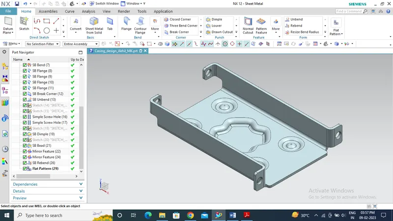
ISOMETRIC VIEW OF SHEET METAL CASING
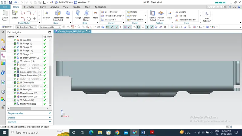
FRONT VIEW OF SHEET METAL CASING
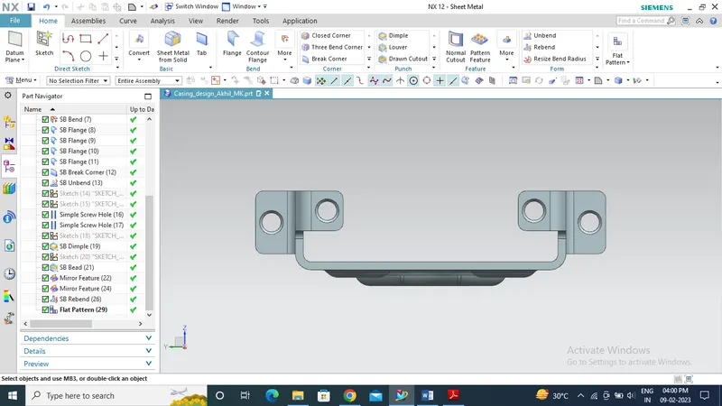
LEFT SIDE VIEW OF SHEET METAL CASING
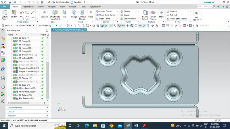
TOP VIEW OF SHEET METAL CASING
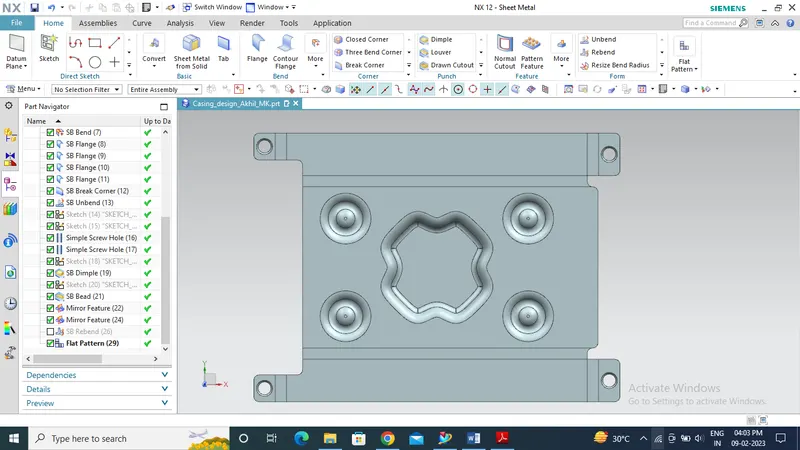
VIEW OF SHEET METAL CASING ON FLAT PATTERN
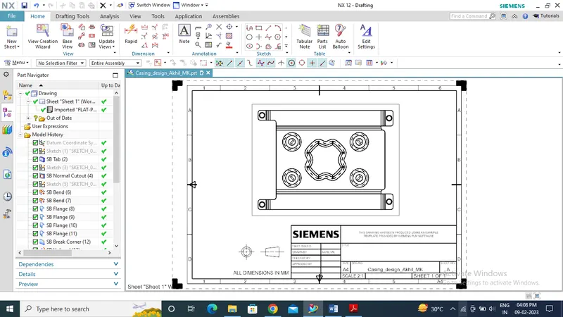
DRAWING OF SHEET METAL CASING ON DRAFTING WORKBENCH
Conclusion
Sheet metal casing was designed and draft drawing was executed with the help of SIEMENS NX CAD by understanding and following the manufacturing process.