Advanced Sheet Metal Design Using NX Cad Challenge_1_Casing Design
Aim:Advanced Sheet Metal Design Using NX Cad Challenge_1_Casing Design
Objective:detailed report on Sheet Metal Component with good explanation on Sheet Metal modelling tools applied throughout the modelling. Also attach the Final model Images (Min. 4 images) of Sheet Metal Casing.
Link for PDF.
https://drive.google.com/open?id=1iFGcicuUq7InjqHUS9Eub5QXL7nwYrOy
Points to be followed in report
- Title of the Project
- Objective
- Introduction
- Design methodology / approach (To be explained with the help of Flowcharts only)
- Description (Need to explain tools/ Features used while designing)
- Upload a min of four screenshots of Model in the report. (Front View, Side View, Isometric View and the Top View)
- Attach Detailed Drawing Sheet Image
- Conclusion
Title of the Project : Advanced Sheet Metal Design Using NX Cad Challenge_1_Casing Design
Objective : To design a Casing with the help of NX advance sheet metal
Introduction :
NX Sheet Metal provides a set of tools within the NX design environment that allows for simple and fast design of sheet metal parts, dependent on their material and manufacturing process. NX sheet metal design software incorporates material and process information in sheet metal-specific modelling features: bends, flanges, tabs, cutouts, beads, dimples, louvers, corner and edge treatments, patterns and other formable features.The sheet metal application provides an environment for the design of sheet metal parts used in machinery, automotive and aerospace application etc. Enclosures, brackets and other parts normally manufactured with a brake press. Through this project we are able to design a sheet metal casing using the digital CAD tool (Siemens NX 12).We can also quickly convert solid models to sheet metal components, and create sheet metal parts that enclose other components.
NX Sheet Metal-specific features such as flanges, tabs, jogs, corner conditions, and drawn cutouts & many more along with productivity enhancements such as – automatic bend reliefs.
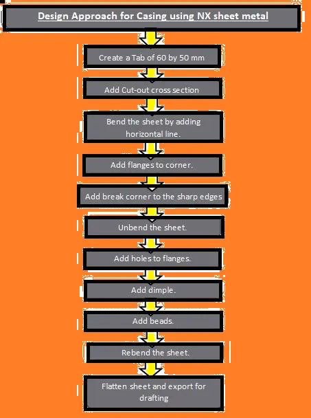
Design methodology / approach (To be explained with the help of Flowcharts only)
Description :
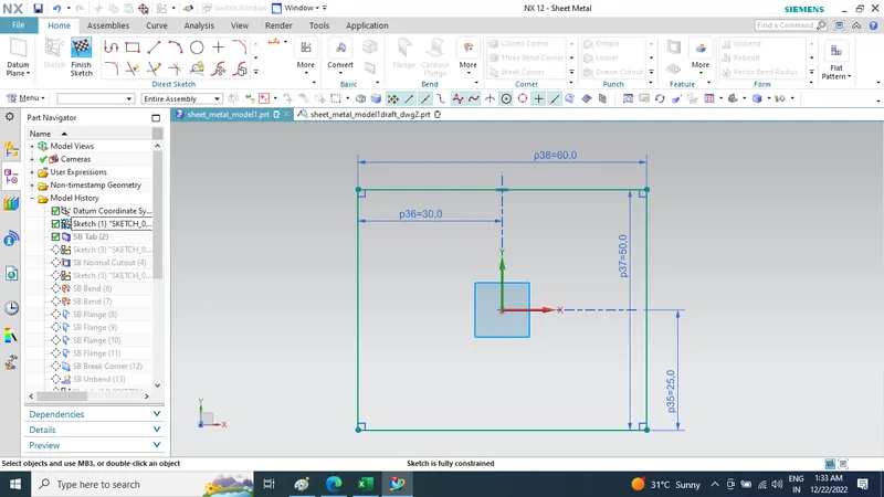
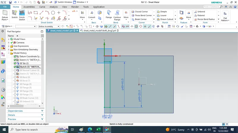
Start sketching in Sheet metal enviornment sketch a rectangle of 60 by 50 mm .
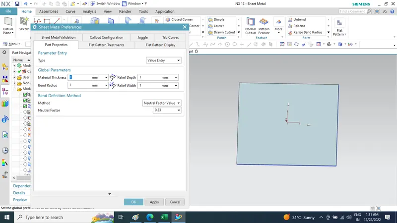
Set the default values in sheet metal preferences in menu tab
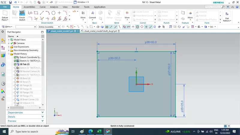
Then creation of Tab.
Sketch on tab face the cross section to create a cut-out.
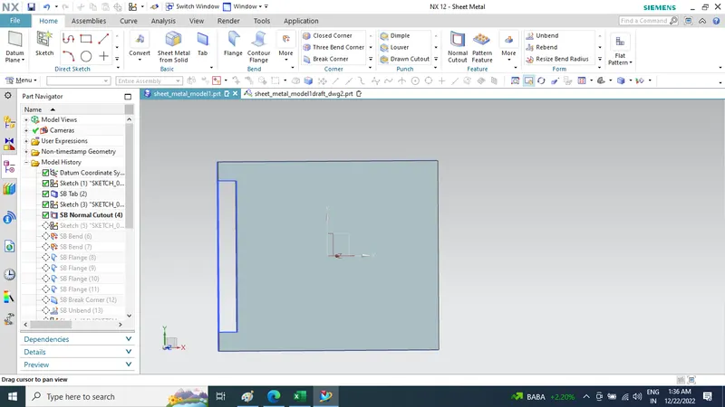
Normal Cut-out feature on sheet
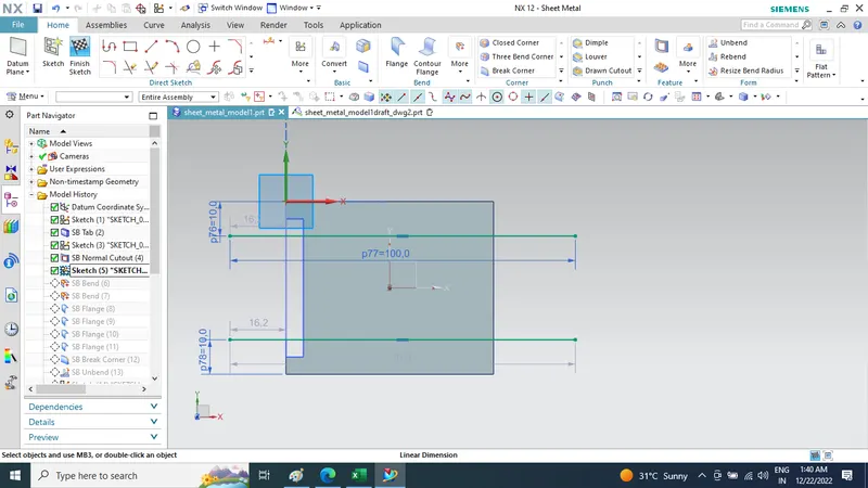
Then Bend the sheet from new sketch drawn two lines symmetry in xaxis and 10 mm offset from horizontal edge of tab
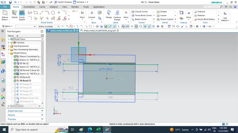
Add flange of 5
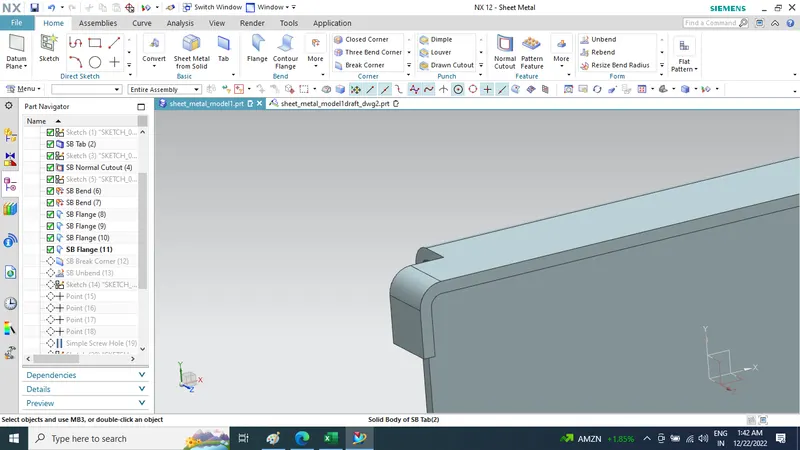
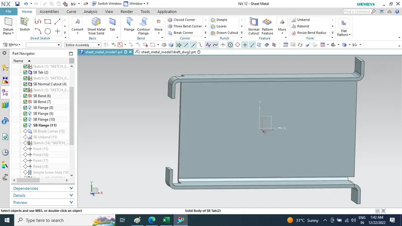
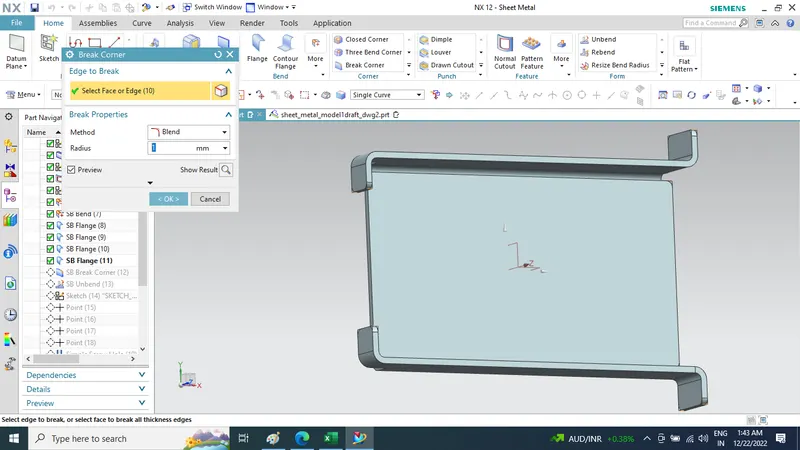
Add Break corner to the sharp edges
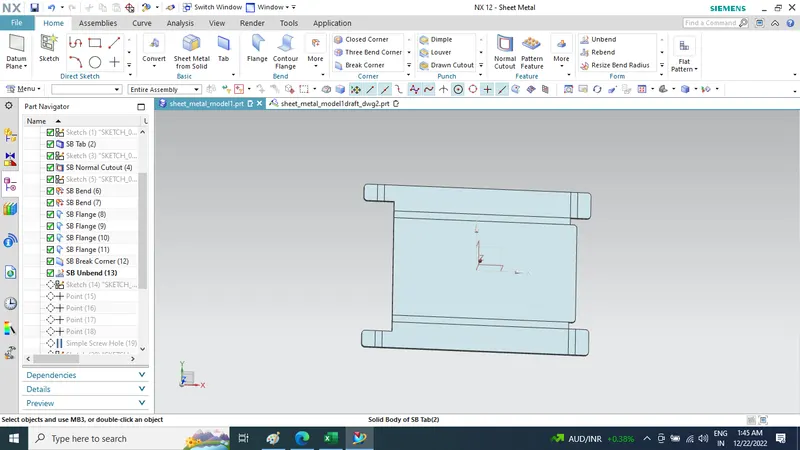
Unbending the sheet.
Make Sketch on C/S And then Creation of Holes to the flanges.
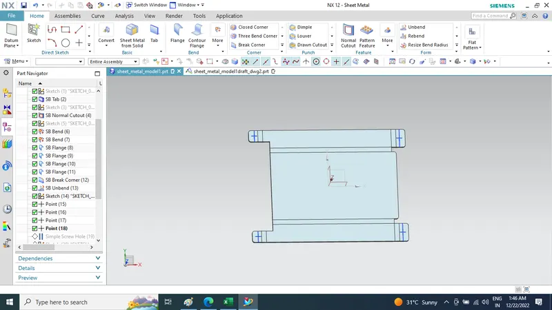
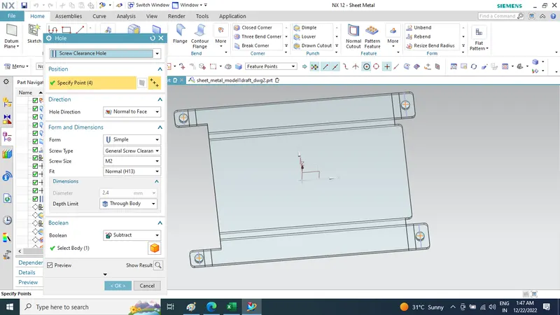
Create Sketch And Adding Dimple by selecting sketch of desired cross section
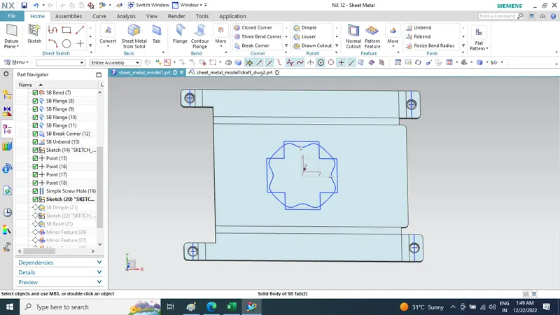
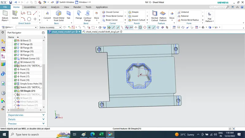
Create Sketch And Adding Bead by selecting sketch of desired cross section
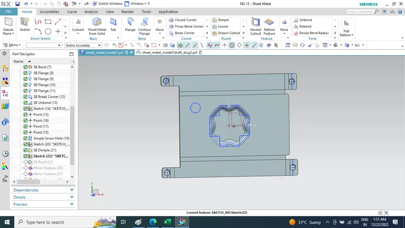
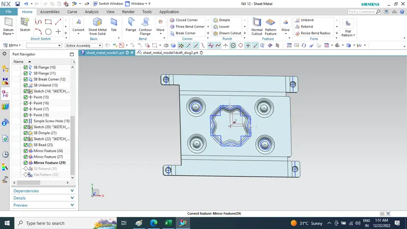
by mirror pattern mirror it with plane axis
Rebending Of Sheet
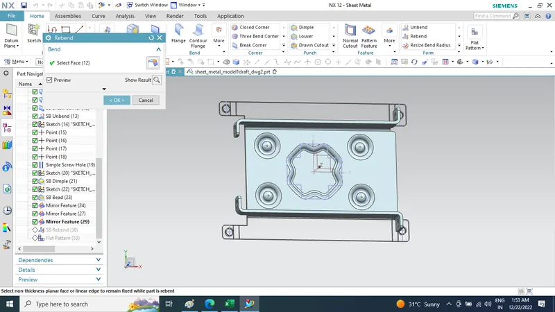
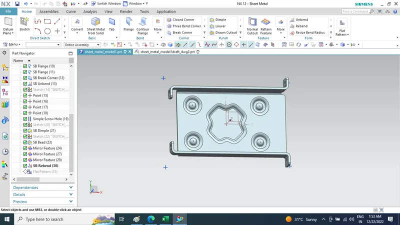
Using Flat Pattern.
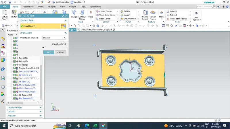
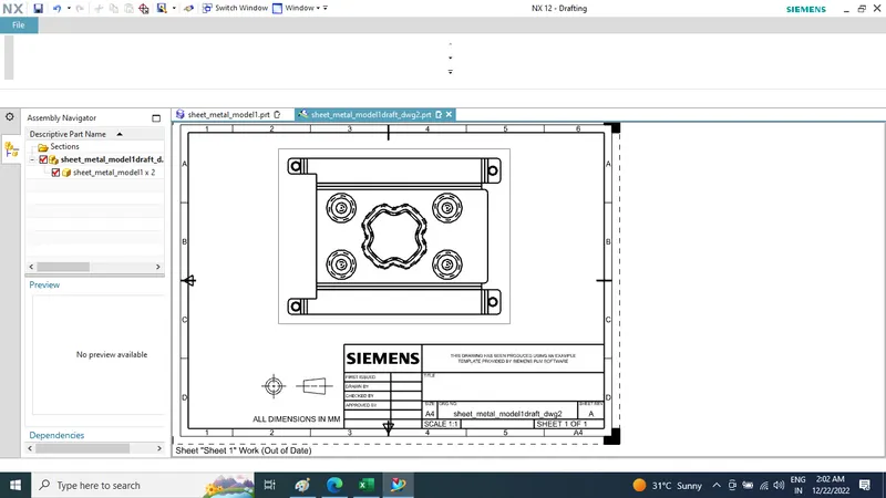
Create New Drafting File and select Module As Flat Pattern
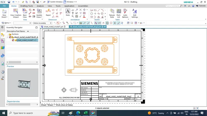
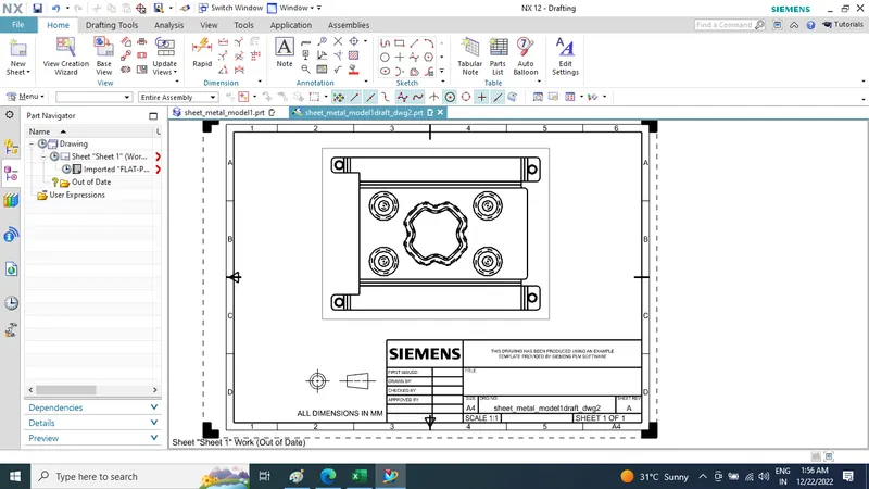
final Casing model Views
Isometric View
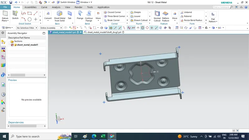
Front View
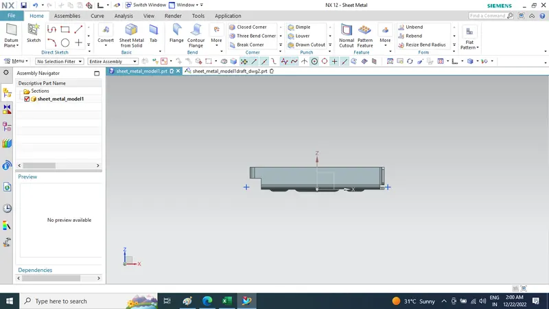
Side View
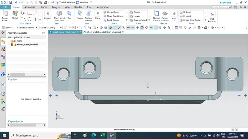
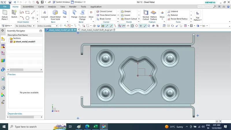
Top View
- Drafting view
CAD File is in zip folder attched with Report Plz Find it
Conclusion :While designing a casing We have Use and learnt different tools such as Tab, Flange, Dimple, Bending, unbending and many more in sheet metal of NX. In this way we have completed Casing modeling using NX sheet metal.