Advanced Sheet Metal Design Using NX Cad Challenge_1_Casing Design
Title of the Project: Advanced Sheet Metal Design Using NX Cad Challenge_1_Casing Design
Objective: To design a sheet metal model of the casing using the NX CAD tool.
Introduction: Sheet metal: It is formed by an industrial process into thin, flat pieces, It is one of the fundamental forms used in metalworking and it can be cut and bent into a variety of shapes it is used in many sectors including the aeronautics & automotive sectors
Design methodology

File Creation: new part file was created by choosing the sheet metal in NXCAD
Sketching: A rectangular sketch is created by selecting the appropriate palne
Cut-out: A cut-out is to be made on the sheet metal base by using the NORMAL CUTOUT feature
Base feature: A base feature is created by using the TAB feature by converting into sheet metal with a thickness of 1mm
Bending: Bend the sheet by selecting the two symmetric lines with a distance of 10mm
Adding flanges: Add flanges on both sides on opposite direction to cut out portion
Break corners: add the corners to edges of sheet by giving radius of 1 mm
Unbend: unbend the parts to sheet by selecting the centre face
Add beads: add fours beads on the top face of sheet
Add holes: Add the holes by selecting the exact midpoint of lines drawn on bended portions
Drafting :drafting should be done for the sheet
FEATURES USED:
SKETCH: This is used to create a basic sketch of the design on selecting the desired plane, then later it can be modelled for the requirement.
TAB: This feature is used to create a base tab on selecting the curve drawn in sketch mode with the appropriate thickness on our desire and it can easily convert that sketch into the sheet.
NORMAL CUTOUT: This feature is used to cut the portions of the sheet metal by assigning sketch curves.
BEND: This feature is used to bend the sheet metal along the sketched curve upon our requirement.
FLANGE: The flanges add flanges on selecting the edges of our sheet metal, it is working as a BEND feature along with that extra material can be added by adjusting the length of the flange.
BREAK CORNERS: Break corners are used to make the edges round for easy handling when using.
UNBEND: Unbend is a feature used to analyze the model whether a part and was perfectly assigned the features, which ensures for a modeler to do further operations on it.
HOLE: It is used for the holes on the requirement for further assembly of the part by assigning different types of specifications of screws.
DIMPLE: It is used to draw a dimple on selecting a curve for modeling the sheet.
BEADS: This feature is used to create a bead on the sheet which generally strengthens it.
MIRROR: It is used to add the material or feature replicates by acting as a mirror to it, this generally reduces the modeling time.
REBEND: This is used to re-bend the object after all conformations and ready for production.
DRAFTING: It is used to provide the dimensions and views of the designed part to the manufacturing team.
CASING DESIGN VIEWS:
TOP VIEW
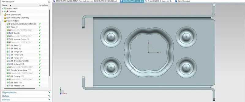
FRONTVIEW:
BOTTOM VIEW: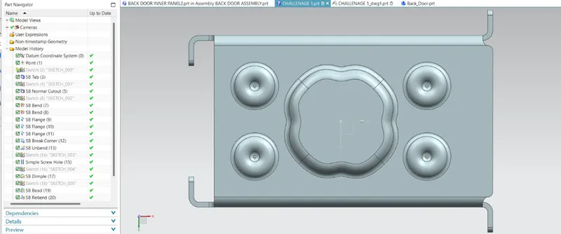
SIDE VIEW:
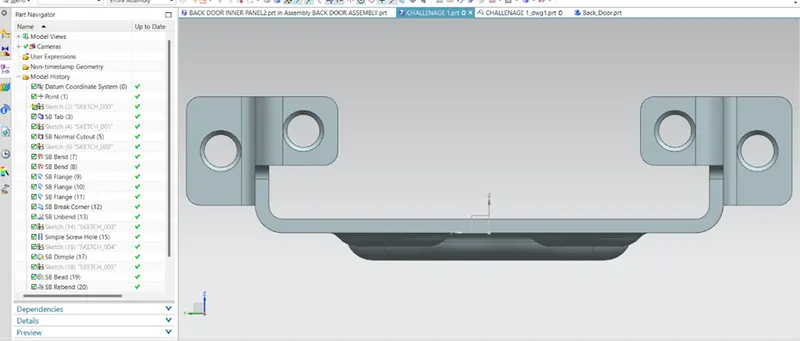
ISOMETRIC VIEW:
FLAT PATTERN:
DRAFTING SHEET: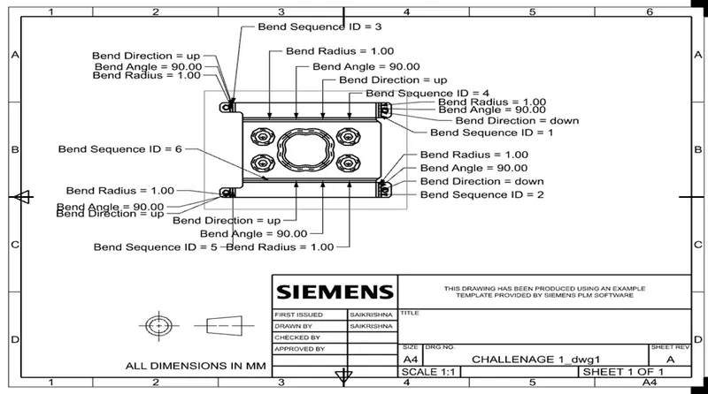
CONCLUSION:
Successfully learn to design a sheet metal casing in industrial manner by using Siemens NX.