Advanced Sheet Metal Design Using NX Cad Challenge_1_Casing Design
Design of the Casing Body in NX CAD
Objective: To design the sheet metal casing using NX CAD and understand how to use the different sheet metal design elements needed to make the sheet metal components based on industrial purpose.
Introduction: Any metal that may be shaped into flat pieces of different thicknesses is referred to as "sheet metal." Plate is the name for thick metals. Cold-rolled steel, mild steel, stainless steel, tin, nickel, titanium, aluminium, brass, and copper are among the metals used in the sheet metal industry. We use software such as Creo, NX, Catia, etc. to design the sheet metals. Depending on the material and production process the most popular of which is straight brake sheet metal forming NX Sheet Metal offers a set of tools within the NX design environment that enable quick and easy design of sheet metal parts. Casing, one of the sheet metal components used to encase or safeguard the interior parts, can be designed using NX's advanced features.
Design methodology:
The following processes are carried out in order to create a sheet metal component.
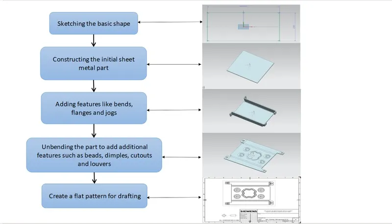
Description:
In order to design the casing, the below features are used to finish the casing design.
- Sketch: For the model of having several sketch commands like lines, rectangles, circles, etc., Sketch creates a 2D graphic.
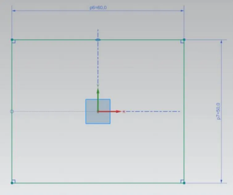
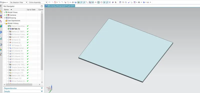
- Tab: For the specified Sketch, Tab produces a Base Extrude feature with thickness and direction.
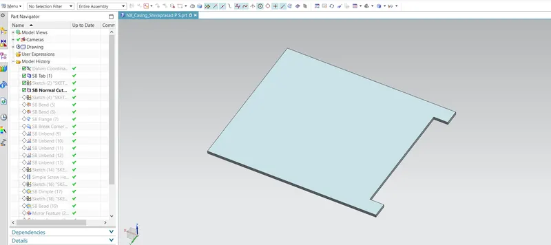
- Normal Cutout: Normal Cutout commands use the principles of sheet metal manufacture to extract volumes from the sheet. Cutting faces will be parallel to the surface of the sheet metal.
- Bend: The produced Base Extrude is bent in the desired direction and angle using Bend.
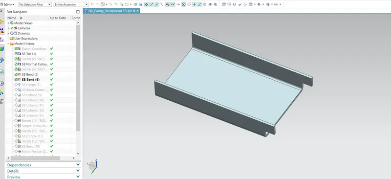
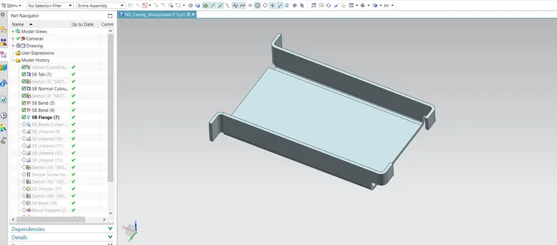
- Flange: The sheet metal flange command in Siemens NX is used to merge two surfaces together by adding a flat flange at an angle to a planar face.
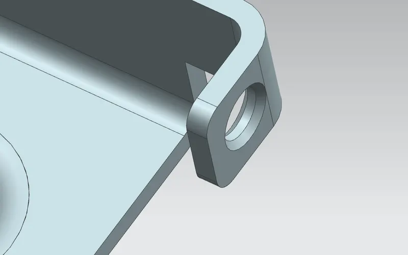
- Brake Corner: It is the tool used to chamfer and round the Sharp edges.
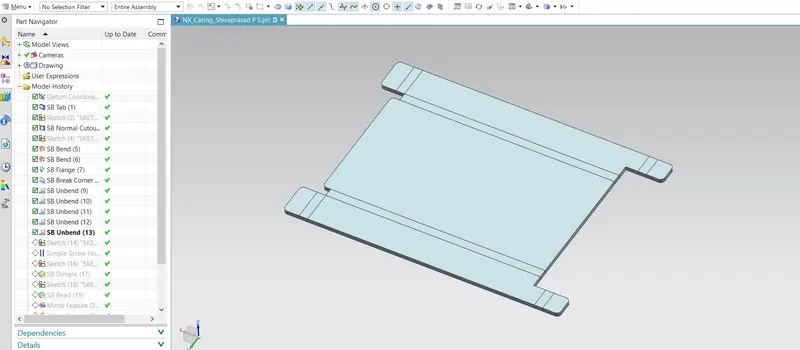
- Unbend: This function is used to flatten bent metal. We must unbend the body in order to add features to the bent section.
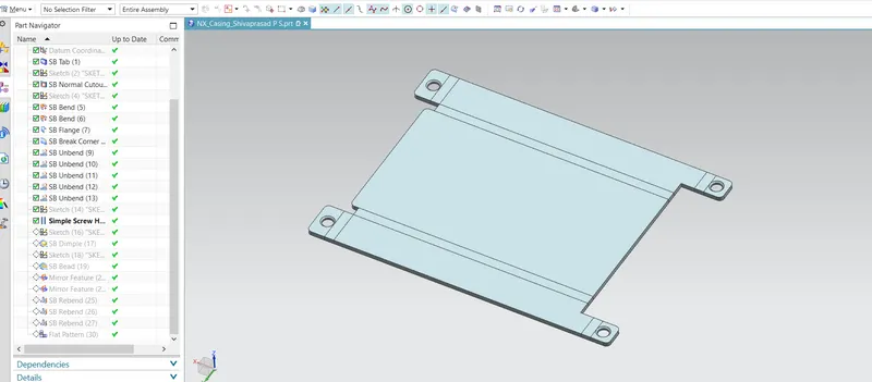
- Screw Hole: On the sheet metal model, holes of various shapes are made using hole.
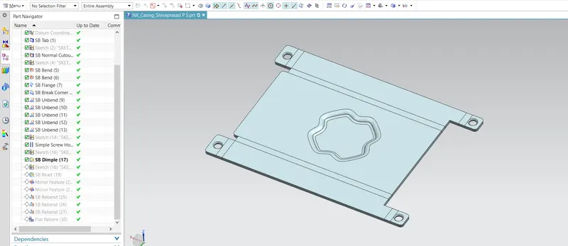
- Dimple: To increase the part's strength, dimples are used. The flat area of the part is weaker and less rigid. Therefore, there is a considerable chance that the part will fail. The dimple decreases the chances of default while enhancing the part's strength and stiffness.
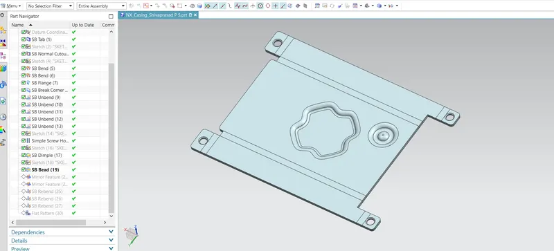
- Bead: A bead that simulates a stamping tool lifts the material along the shape of the sketch.
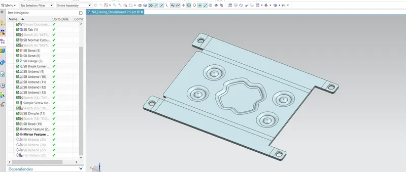
- Mirror Feature: The command "Mirror Feature" copies and pastes features into the model by reflecting them via a plane or surface.
- Rebend: After adding the characteristics, the feature is restored to its previously bent state.
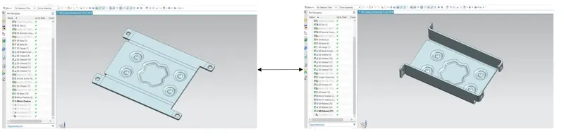
- Flat Pattern: A flattened pattern of the sheet metal item is made to be used in drafting.
Views:
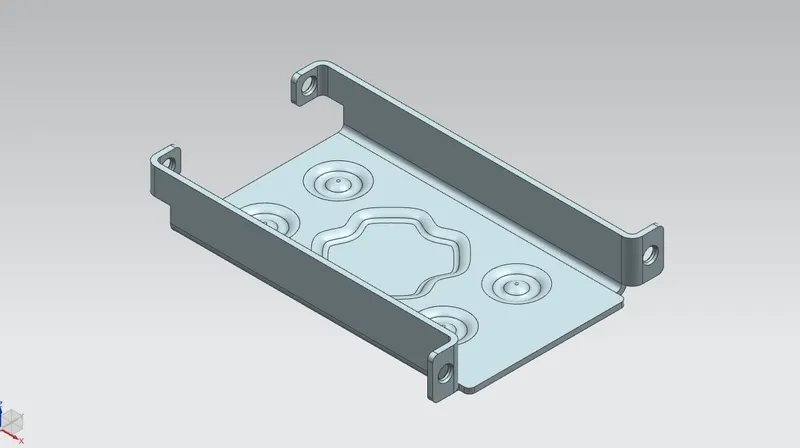
Isometric View
Front View
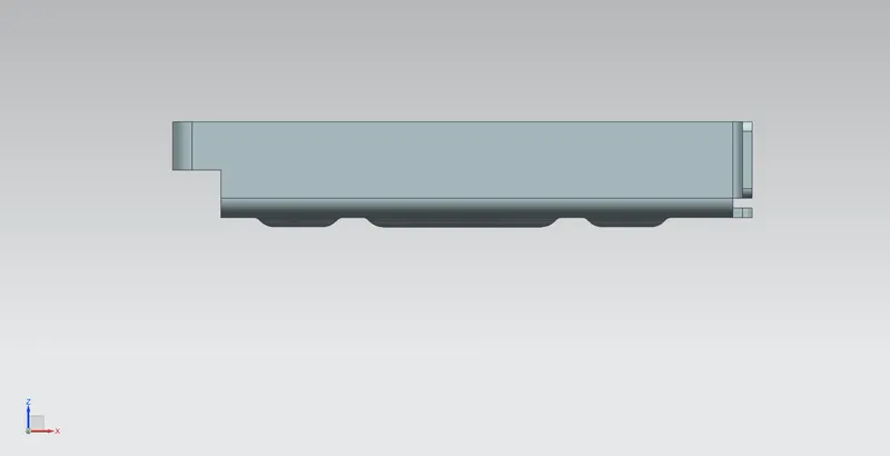
Left View
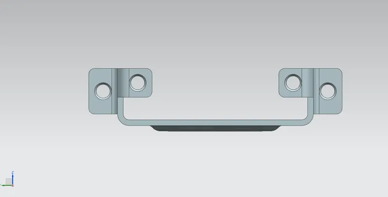
Right View
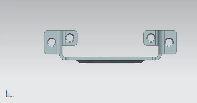
Top View
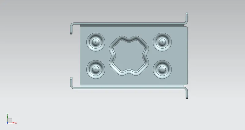
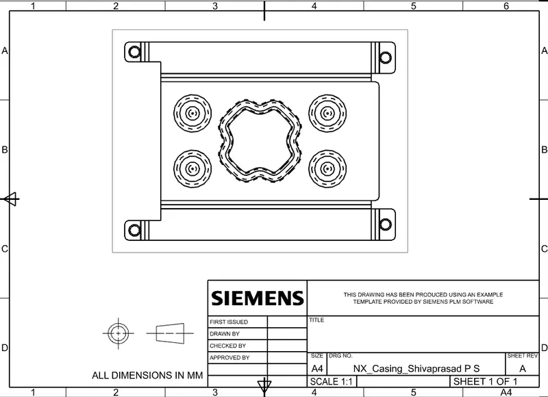
Drafting View
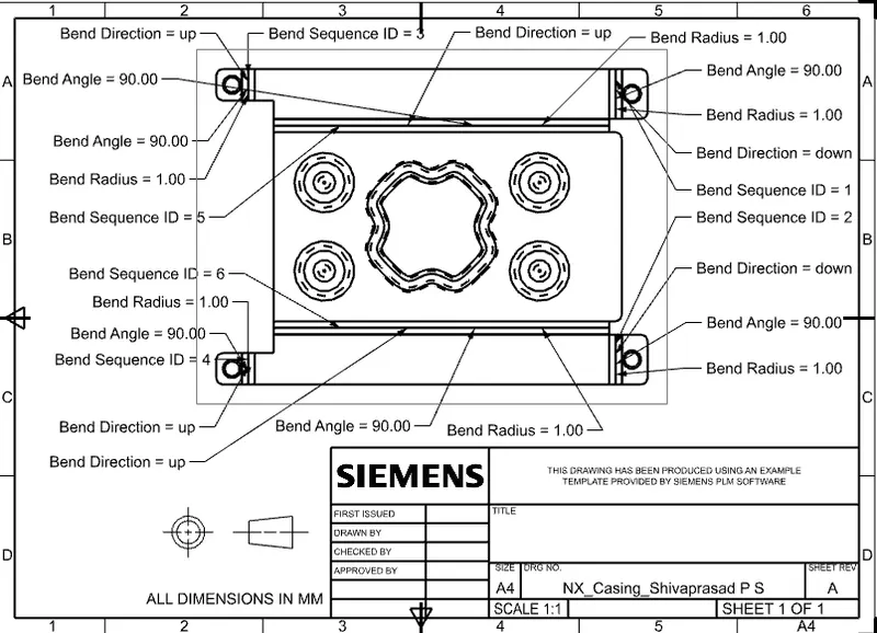
Conclusion: Hence NX cad is used to design the casing portion with the specified dimensions.