Advanced Sheet Metal Design Using NX Cad Challenge_1_Casing Design
ADVANCED SHEET METAL DESIGN USING NX CAD - CASING DESIGN
Objective :
To create the sheet metal casing by using NX CAD sheet metal tools and to understand the various tools in NX CAD sheet metal user interface.
Introduction :
Sheet Metal -
The sheet metal is formed by an industrial process into thin, flat pieces. Sheet metal is one of the fundamental forms used in metal working, and it can be cut and bent into a variety of shapes. The metals which are less 6 mm thickness are considered as sheet metals. The sheet metal is available in flat pieces or coiled strips.

The various forming processes that are used to deform the sheet metals are -
Bending
Curling
Deep drawing
Hemming and Seaming
Punching
Blanking and Peircing
Rolling, Spinning and Stamping
Sheet metal is used in automobile and truck bodies, airplane fuselages and wings, medical tables, roofs for buildings and many other applications.
NX CAD in sheet metal -
NX sheet metal design software incorporates material and process information in sheet metal-specific modeling features: bends, flanges, tabs, cutouts, beads, dimples, louvers, corner and edge treatments, patterns and other formable features. You can also quickly convert solid models to sheet metal components, and create sheet metal parts that enclose other components.
NX Sheet Metal-specific features such as flanges, tabs, jogs, corner conditions, and drawn cutouts & many more along with productivity enhancements such as – automatic bend reliefs.
The software also provides common modeling features typically used in sheet metal design, such as holes and slots, as well as other essential capabilities such as copy, paste, and mirror.
The application provides defaults for sheet-metal-specific properties such as material – thickness, bend radius, and bend relief. You can easily change these defaults.
Design methodology :
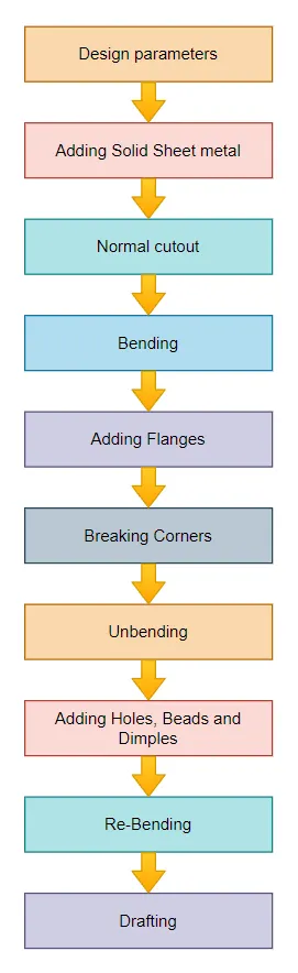
Description :
1. Open NX CAD, create a model with file name and location. Now start the sheet metal from applications.
2. Open the preferences and set the thickness of sheet to 1 mm and also set bend radius, relief depth and relief width as 1 mm.
3. Create a sketch of rectangle in XY plane with 60 x 50 mm.
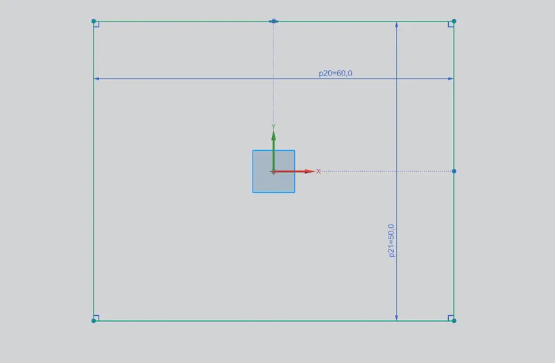
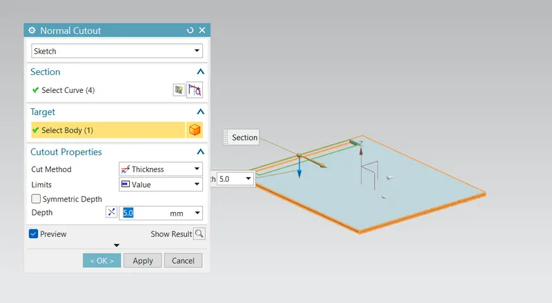
4. Create a cutout of 5 mm wide and 40 mm long on left edge.
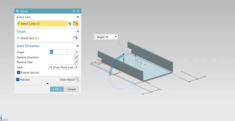
5. Draw two symmetric lines from the top and bottom ends at a distance of 10 mm from the edge. Now create the bend.
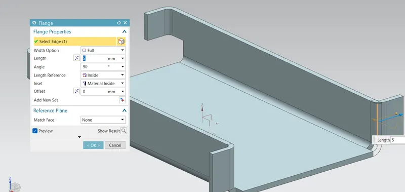
6. Add flanges with a length of 5 mm as shown in the below picture.
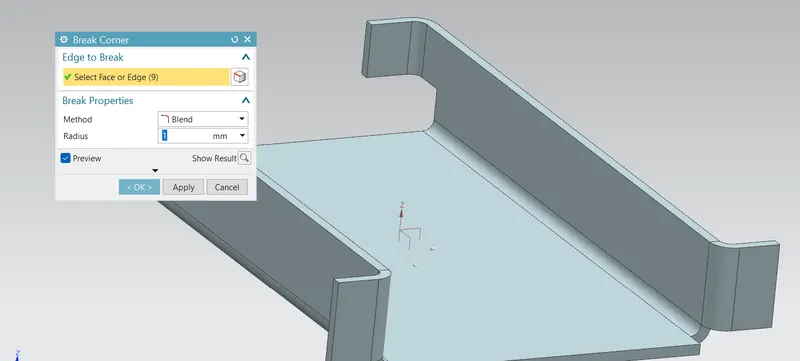
7. Smooth the all sharp edges using break corner operation.
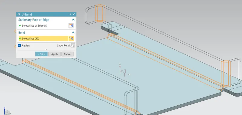
8. Unbend the sheet metal
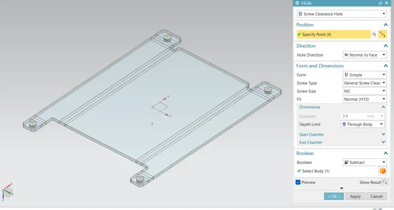
9. Create the points on the edges of the sheets to locate the hole. Create screw clearance holes of size M2.
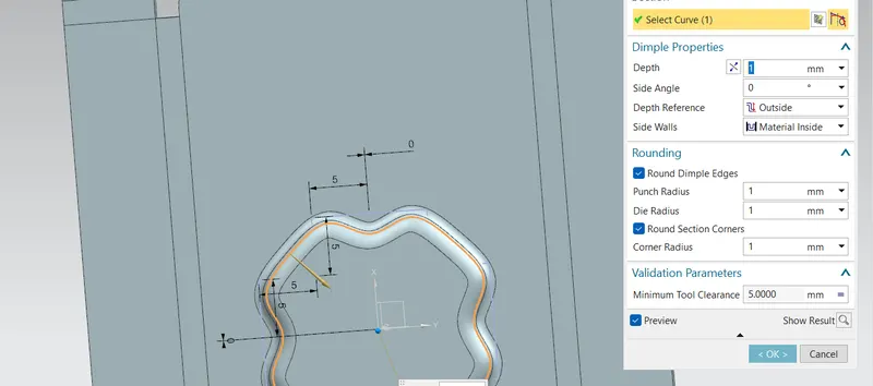
10. Adding dimple, sketch the profile as shown.
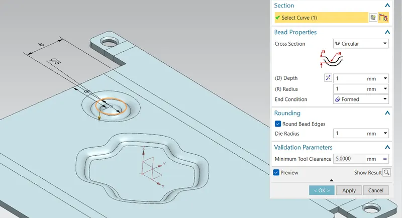
11. Adding beads
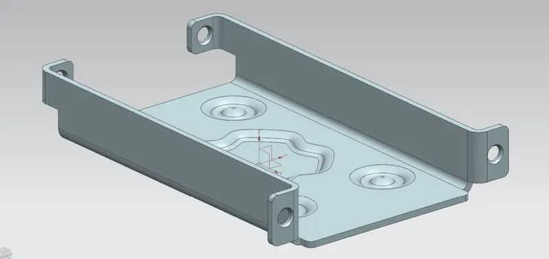
12. Re-bend the sheet metal faces.
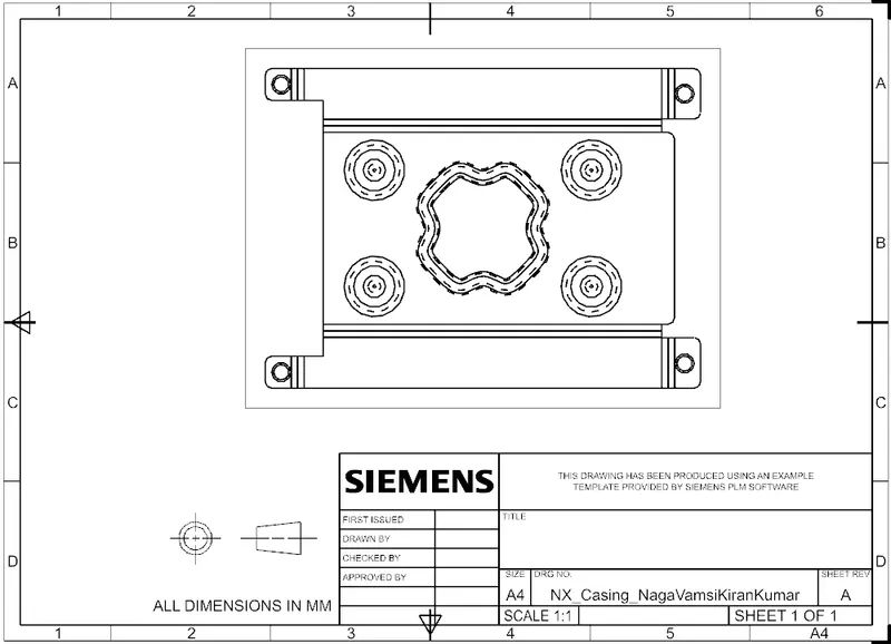
13. Creating Drafting
Views :
Front view -
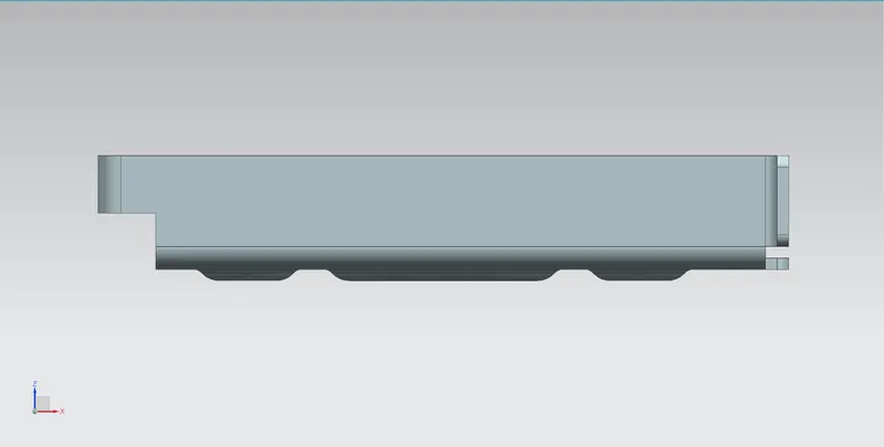
Side view -
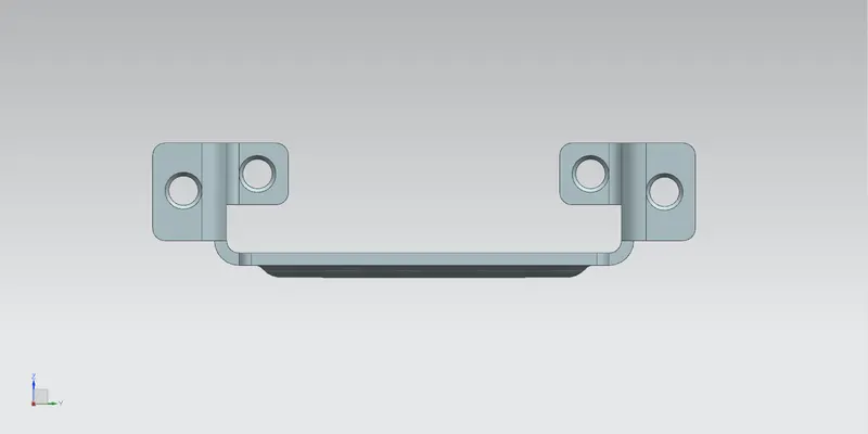
Top view -
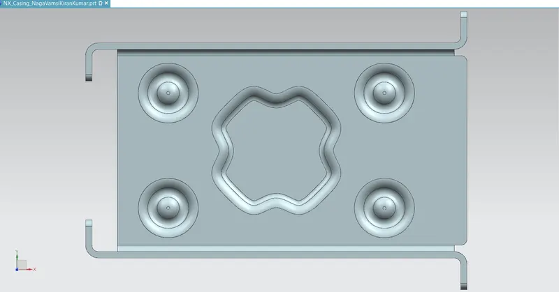
Isometric view -
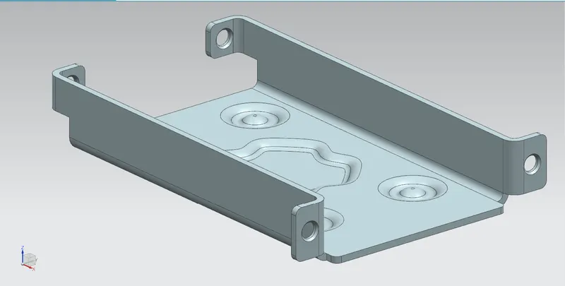
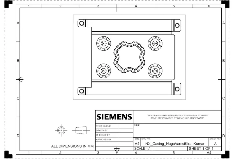
Drawing sheet image :
Conclusion :
The given casing design model is successfully created using NX CAD sheet metal and drafting views are created.