Advanced Sheet Metal Design Using NX Cad Challenge_1_Casing Design
{}:CASING DESIGN USING NX CAD:{}
Objective: The objective of this project is to design a Sheetmetal Casing using Siemens NX Sheetmetal Application.
Introduction:
Siemens NX is one of the popular CAD Software used for 2D drafting and 3D modeling. It has complete set of tools for creating sheet metal parts. Here by we have used varies tools of NX 10 for creating casing design using different features
The design casting involves following steps: -
- 3D Designing of Casing.
- Creating Flat pattern.
- Drafting of sheet metal.
Design Methodology:
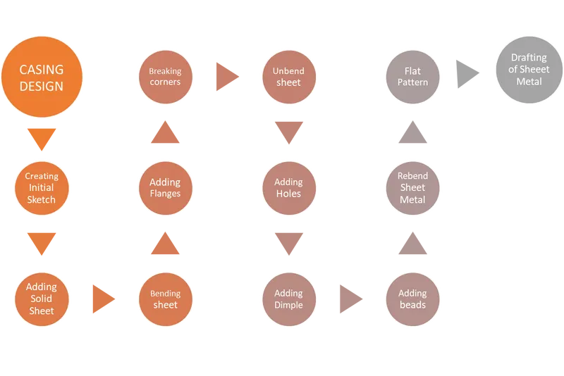
Description:
CREATING SKETCH: Sketch of given dimension is created after selecting the required plane with the help of Sketch Tools.
SKETCH TOOLS: Sketch tools are used for creating 2D sketches in Siemens NX.
Following Sketch Tools are used throughout the designing of casing:
- Straight Line: The straight-line command is used to draw a straight line.
- Arc: This command is used to create Arc. Arc can be Created through three points or by specifying its centers and endpoints.
- CIRCLE: This command is used to create Circle. It can be created through three points or by specifying its centers and diameters.
- RECTANGLE: This command is used to create Rectangle. It can be created using any of center Rectangle method or corner Rectangle method.
- POINT: It is used to create sketch points.
- ELLIPSE: This command is used to create ellipses by using center points and dimensions
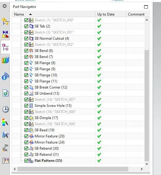
ADDING SOLID SHEET AND CUTOUT: Sketch is molded to a Rectangular Solid Sheet using TAB feature from feature bar.
- TAB: Tab feature by extruded a sketch to a given thickness value and to a given vector.
After creating Solid Tab by using Normal Cutout feature a rectangular hole is created at the left side of the created tab
BENDING SHEET: Following the normal cutout the sheet metal is bend according to requirement of Design by using the Bend Feature.
- BEND: Bend feature is used to bend material on one side of a sketch line, adding a bend between the two sides
ADDING FLANGES: Flanges are added at the edges of metal sheet as per the requirement of design by using Flange feature.
- FLANGE: This feature is used to extrude or add a flat material at an angle to a required tab
BREAKING CORNERS: Sharp corners are blunted by using Break corner Features.
- BREAK CORNER: This feature is used to blunt sharp corner by providing radius to corners.
UNBENDING SHEET: Metal sheet is unbent to creating flat sheet for further proceeding by using Unbend feature.
- UNBEND: It is used to flatten the material by removing the bends
ADDING HOLES: Holes are added according to the requirement of design by using holes feature.
- HOLES: This feature is used to create different type of holes.
ADDING DIMPLE AND BEADS: Dimple and bead are added at the center of design.
- DIMPLE: It is used to lift an area of the model inside a sketch that simulates a stamping tool.
MIRRORING FEATURE: Bead is mirrored symmetrically around the metal sheet
- MIRROR: It is used to mirror the features symmetrically.
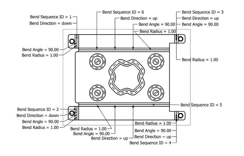
DRAFTING AND FLAT PATTERN: Finally, the Flat pattern and drafting with detail is created from the final Design of the casing.
Screenshots:
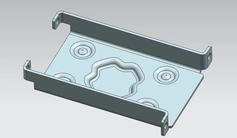
1.ISOMETRIC VIEW:
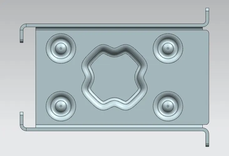
2. TOP VIEW:
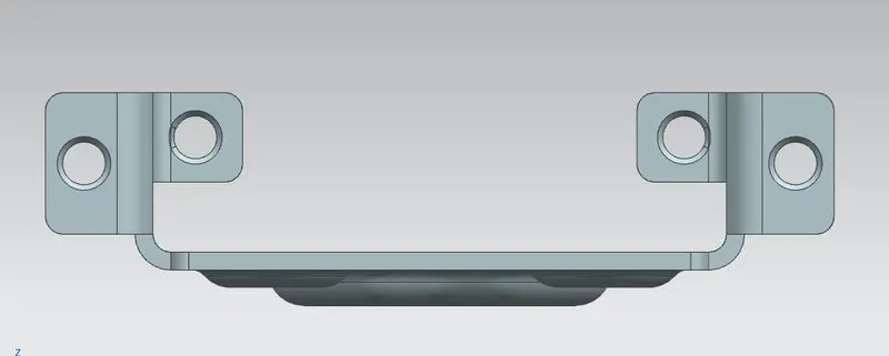
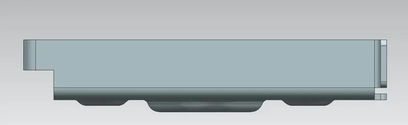
3.SIDE VIEW:
4.FRONT:
5.PART TREE:
Detailed Drawing Sheet Image:
Conclusion:
Thus, the designing of Sheetmetal Casing using Siemens NX Sheetmetal Application is done successfully.