Advanced Sheet Metal Design Using NX Cad Challenge_2_Box Assembly
: SHEETMETAL BOX ASSEMBLY DESIGN USING NX CAD :
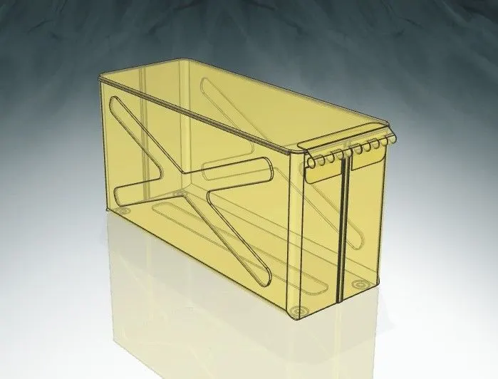
Objective: The objective of this project is to design 'Sheetmetal Box Assembly' using Siemens NX Sheetmetal Application.
Introduction:
Siemens NX is one of the popular CAD Software used for 2D drafting and 3D modeling. It has complete set of tools for creating sheet metal parts. Here by we have used varies tools of NX 10 for creating Sheetmetal box assembly using different features. The design of Box Assembly consists of following attached elements:
- Base
- Lid
- Hinged Mount
Design Methodology:
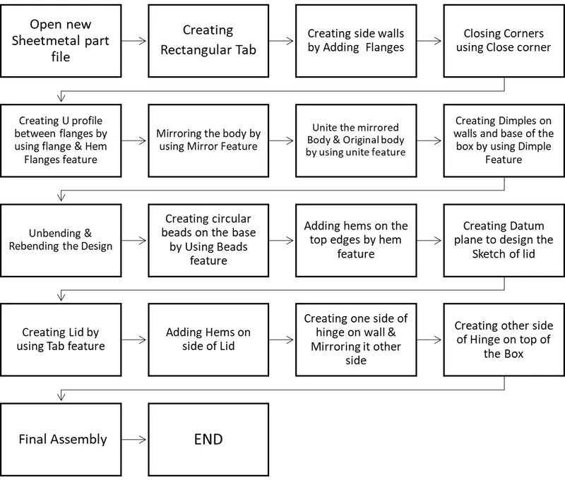
Description:
- The Design of Box Assembly is Created using following feature.
SKETCH TOOLS: Sketch tools are used for creating 2D sketches in Siemens NX. The sketch tools used are straight line, Rectangle, Arc and circle.
TAB: Tab feature by extruded a sketch to a given thickness value and to a given vector.
- Base of box and base of hinge mount are created using this feature
FLANGE: This feature is used to extrude or add a flat material at an angle to a required tab.
- Side walls and hinge mount are created using this feature
CLOSE CORNER: This feature is used to Closes two adjacent flange corners in sheet metal application.
- Corner of base tab and wall flanges are closed using this feature
HEM FLANGE: This feature is used to modify the model by folding the edge of a sheet metal flange over onto itself for the purpose of safe handling or to increase edge stiffness.
- This feature is used to create U profile between flanges of side wall, hems on the top edges of walls and side of Lid.
MIRROR: This feature is used to copy and mirror any feature or a body across a plane.
- Half created body is mirrored to create other side of the of the box
UNITE: This feature Combine the volume of two bodies or more bodies into a single body.
- Mirrored body and the original body are united using this feature.
DIMPLE: This feature is used to lift an area of the model inside a sketch that simulates a stamping tool.
- Dimple is created on the side of walls and base of the material.
UNBEND: It is used to flatten the material by removing the bends.
REBEND: It is used to rebend the flatten Design.
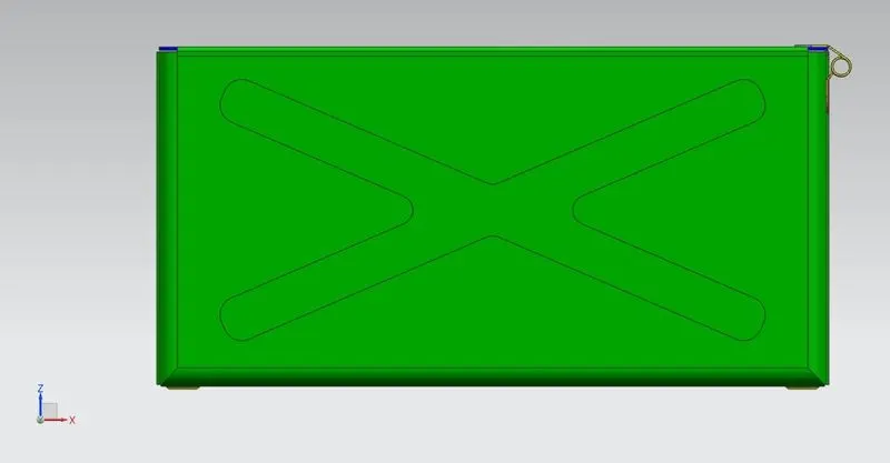
BEAD: It is used to lifts material along the contour of a sketch that simulates a stamping tool.
- Using this Feature Bead is created on the base tab.
BREAK CORNER: This feature is used to blunt sharp corner by providing radius to corners.
- Corner of Hinge Mount is blunt using this feature.
NORMAL CUTOUT: This feature is used to cuts material by projecting a sketch onto the model and then cutting perpendicular to the faces intersected by the projection.
- This feature is used in designing of hinged mount.
SCREENSHOTS:
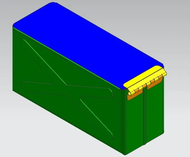
ISOMETRIC VIEW:
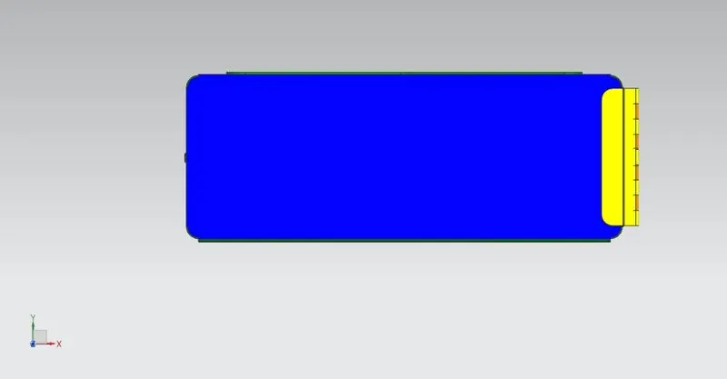
TOP VIEW:
RIGHT SIDE VIEW:
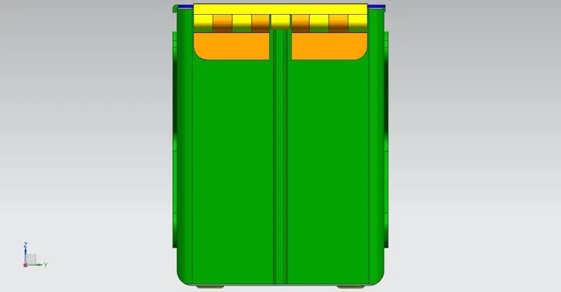
BOTTOM VIEW:
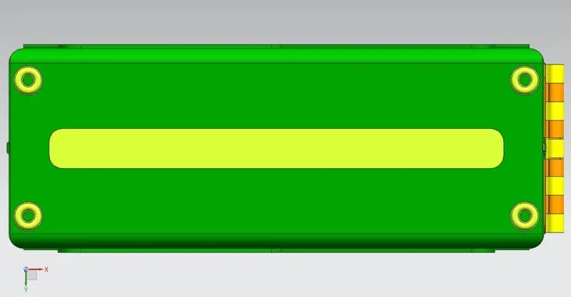
FRONT VIEW:
Conclusion:
Thus, the designing of Sheetmetal Box Assembly using Siemens NX Sheetmetal application is done successfully.