Advanced Sheet Metal Design Using NX Cad Challenge_1_Casing Design
The Advanced sheet metal design of the Casing component is made with the proper method using the sheet metal application.
1) The Title of the project is;
Sheet metal Casing component.
2) Objective
To create a sheet metal casing design component using the NX is that power house of the hyroelectric development project is the place where the potential and kinetic energy of the water flowing through the water conducting system is transferred into mechanical energy of rotation turbines and is then further converted into a electrical energy by generator.
The purpose of the generator is to convert mechanical energy into a electrical energy.This electromechanical energy conversion is realized with magnetic field inside the generator acting as a intermediate coupling.
3) Introduction of Casing design of sheet metal.
The generators have been designed based on many conventional methods and regular practices related to the prevailling technology.
The stator consist of stator of casing,winding and stator core.
The classification of the casing design is made with this passion,
1* Outside Diameter
2* Inside Diamter
3* Uniform Wall thickness.
4* Drift Diamter
5* Length
Outside diameter.
Casing manaufacturers generally try to prevent the pipe from being undersized to ensure adequate thread run out when machining a connection.
Inside diameter.
In inside diamter is specified in terms of wall thickness drift diamter, the maximum inside diameter is controlled by the combined tolerance for the outside diameter and the wall thickness.
Length
The length of pipe sections are specified in three major ranges.
i.e. R1, R2 & R3.
4) Design methodology of the casing component.
The design of casing is done with the proper method followed by the application of advanced sheet metal application from the starting of the sheet metal component.
5) Description of the model and tools used in this projects are ;
In The initial of the casing design we created a reactangular of size 60mm length and a width of 50mm in the XY plane component.
after creating the rectangular shape component we nee to add the tab to it with a minimum thickness of 1mm of sheet metal component.
after creating the Tab, we need to create a normal cutout with a given dimensions for the diagram with a width of 5mm and a length of 40mm.
after this we need to create two horizontal lines which are some distance from the top left corner of the casing component and bottom keft corner of the casing component.
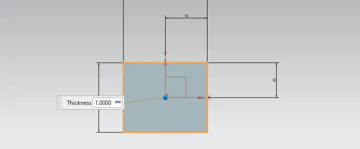
The tab of the component is made with a thickness of 1mm is shown in the above figure.
The normal cutout of the component is shown in below figure.
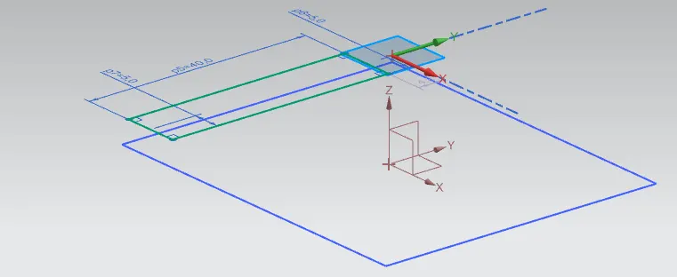
after creating the normal cutouts and two horizontal lines over the plates we will add the flanges over the casing component at the edges over it. After that add the breaking corners to the all edges with a minimum radius of 1mm throughout the part.
After creating the normal cutouts we should add flanges to the part so to get grip for the part.
applied flanges are as shown in the figure.
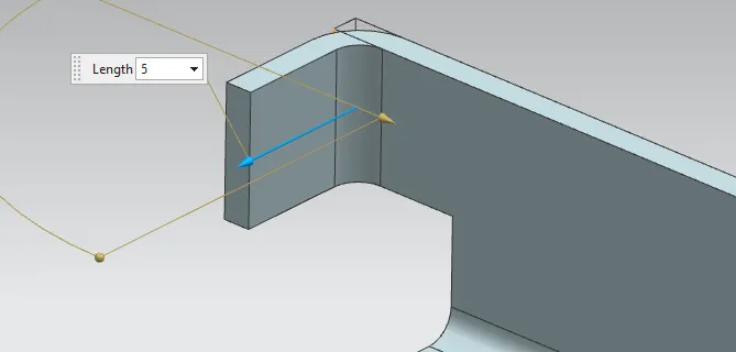
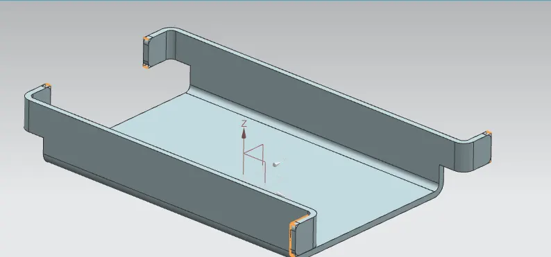
The breakimg corners are applied to the end of the erach corners to sharpens the edges and get fit into the part of the machining component.
The breaking corner components are shown in the below figure.
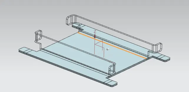
After this process we need to unbend the casing of the sheet metal component and get the exact shape of the component in order to get the required shape of the component.
It's done by selecting the stationary face of the horizontal component and do the same procedure on both the sides and get back the required shape of the casing design.
The umbending of the casing component is inserted in the below figure.
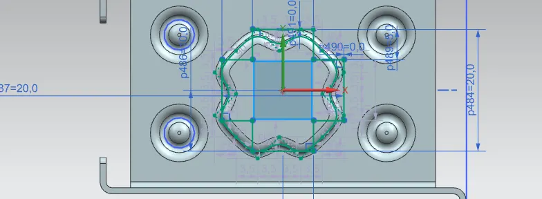
To get the dimple of the casing component we need to make a sketch of the dimple with the proper dimensions given for the creation of it.
Each side it sholud be of 5mm and to be considered from the origin of the cooordinate system.
The rectangular shape of the component is 5mm on each side and make a spline curve by adding together all the 16 points from the rectangular cutout section.
Spline is to be made to withstand the casing component to held the parts together and can be able to load the weights.
The spline component of the casing design of sheet metal is shown in the below figure.
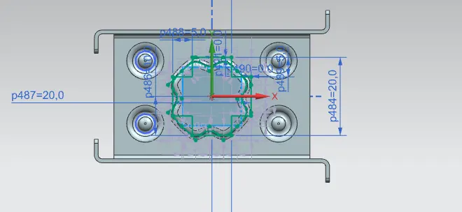
All the four dimples are made with the proper dimensioning method. make a dimple of the hole size diameter of 5mm and it should be 8mm away from the top left corner of the sheet metal component.
The dimple size diamter is to be maintained as 1mm and material should be inside material and rounding diamter has to be maintained as 1mm to create a dimple diagram.
The die radius is to be maintained as 1mm for the creation of dimple on casing component.
Finally rebend the casing component with the selection of all the parts made with proper method.
The rebend picture is as shown in the figure.
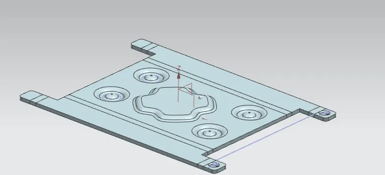
The final part of sheet metal application of casing design is to be flattened the design component to create a 2D representation of 3D sheet metal part.
The flat pattern of the casing design is shown in the below figure.
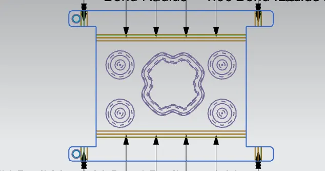
6) The four views of the models are attached below.
**Front view.
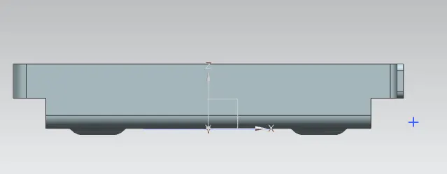
** isometric view.
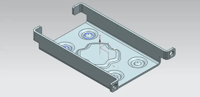
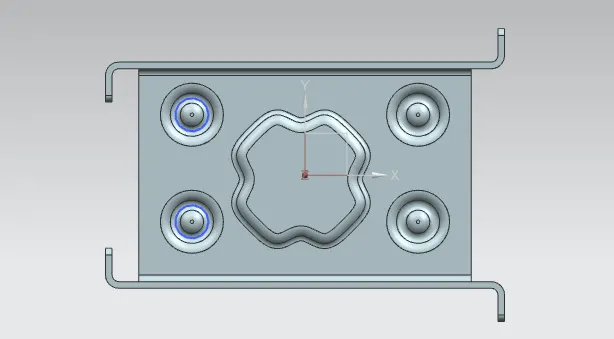
**Top view.
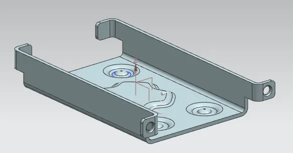
**Trimetric view.
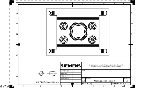
Attaching the drawing sheet of casing design application;