Advanced Sheet Metal Design Using NX Cad - Casting Design
OBJECTIVE:
- To design a sheet metal casing using NX Cad.
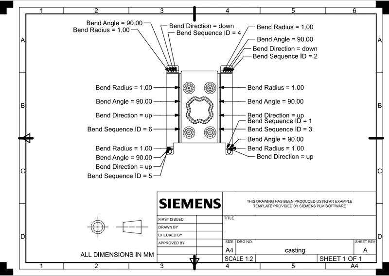
- To create drafting of the same in the A4 Sheet.
INTRODUCTION:
Sheet metal can be cut and bent into a variety of shapes. Countless everyday objects are fabricated from sheet metal.
DESIGN METHODOLOGY:
1. setting the sheet metal preferences
2. adding the base feature
3. adding the secondary features
4. unbending the sheet metal to add punch or cutout features
5. create a flat pattern of sheet metal.
DESCRIPTION:
Tools with their functions:
Sketch: it is used to create a profile.
Tab: it is used to create a base feature of sheet metal.
Flange: it is used to create extended parts on sheet metal.
Unbend: it is used to unbend the sheet metal by taking any face as a stationary face.
Rebend: it is used to rebend all the bent faces.
Dimple: it is used to lift an area of the model inside a sketch that simulates a stamping tool.
Bead: it is used to lift material along the contour of ta sketch.
Flat pattern: it is used to create a 2D representation of flattened 3D sheet metal.
Normal cutout: it is used to cut a portion of sheet metal.
Bend: it is used to bend the sheet metal.
Flanges: they are added to the ends of the bends.
Break corner: it is used to create a smooth edge at the sharp corners.
STANDARD VIEWS:
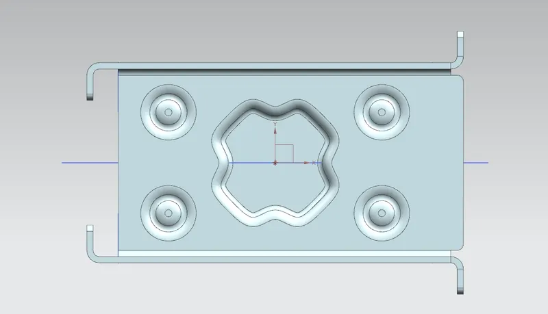
TOP VIEW:
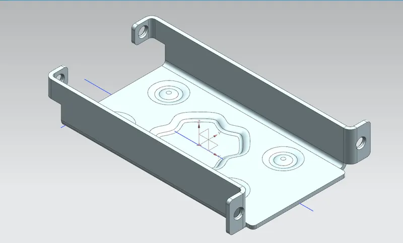
ISOMETRIC VIEW:
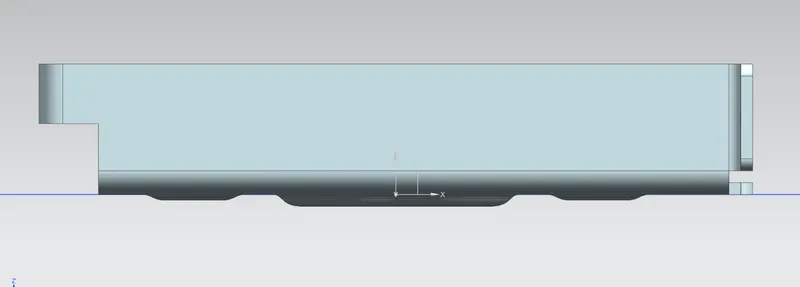
FRONT VIEW:
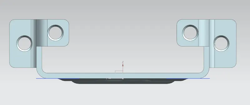
SIDE VIEW:
BOTTOM VIEW:
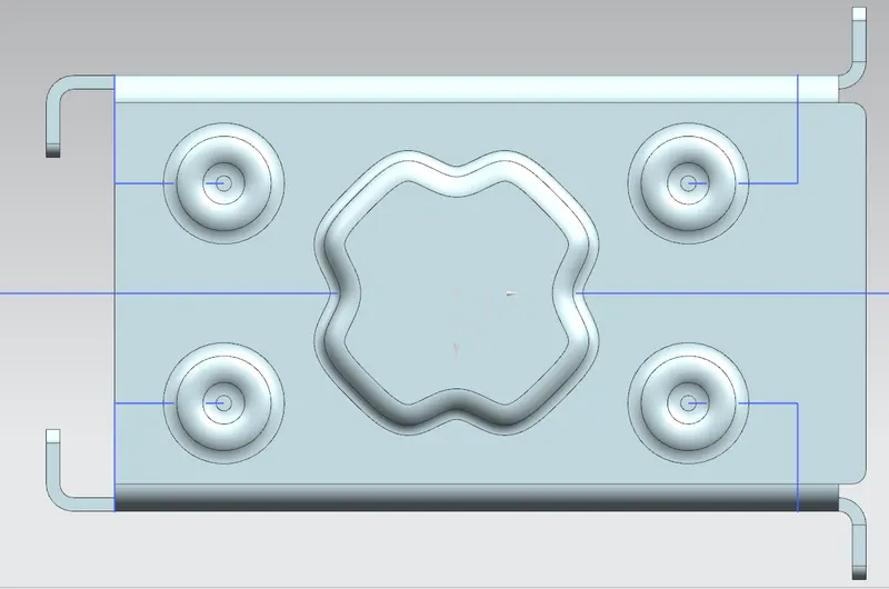
Drawing sheet:
CONCLUSION:
The sheet metal casing is successfully designed using NX Sheet metal Workbench.