Adams Assignments – Problem 5 – Compliance
Aim: Perform appropriate simulations and find out the following compliance related parameters (on-center gradients)
Models : Rear Multilink (created from Acar library using the multilink template)
Part 1: Baseline analysis
Brake steer (deg/m). State whether the suspension toes in or out under braking.
Traction steer (deg/m). State whether the suspension toes in or out under braking
Longitudinal wheel center recession under traction (mm/kN). Find out the same number under braking and state why the two are different
Lateral force compliance steer (deg/kN). Explain whether this is an understeer or an oversteer effect
Lateral force compliance camber (deg/kN). Explain whether this is an understeer or an oversteer effect
Perform appropriate simulations and find out the bump steer. State whether it is an understeer or oversteer effect
Part 2: Tuning
You are required to tune only one parameter at a time to understand the effects of tuning correctly. Also remember this is a multilink suspension. Any change you make affects a lot of parameters. So when asked to tune a parameters, you will have to find out the right tuning knob.
Optimize the hardpoints to achieve a bump steer of +2.6 deg/m. Is this now an understeer or oversteer effect?
Optimize the bushings (one bushing at a time) to achieve the following. For both cases, explain which bushing you changed and why
Traction wheel center recession – stiffness of ~500 N/mm
Camber compliance of 0.45 deg/kN.
Steps:
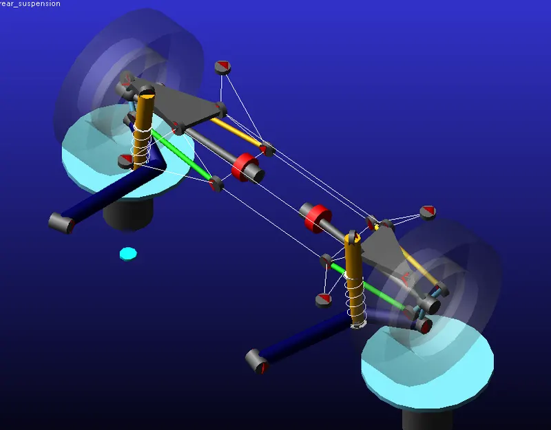
Rear multi-link suspension is created and opened in adams to simulate the following results. The rear multi-link suspension is shown below,
Now lets simulate the model for static load once under braking and in traction with a load of 0 and 5000.
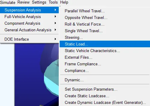
Click on simulate, suspension analysis and then static load as shown below,
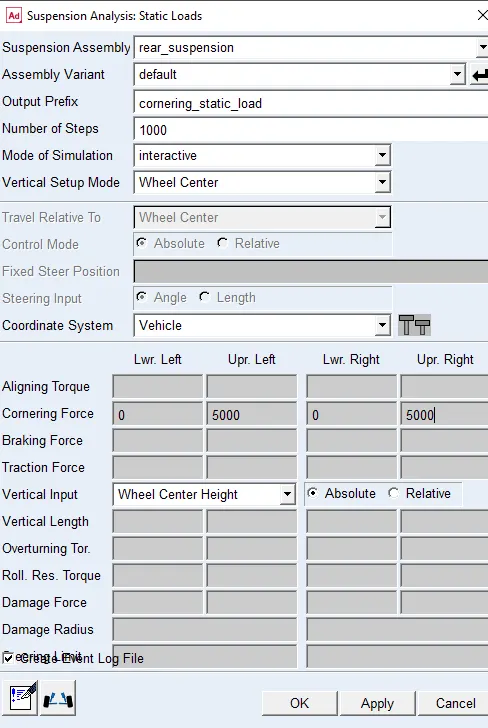
Here wename the simulation as 'Brake_static_load' which has 1000 steps and a braking force is applied as shown below,
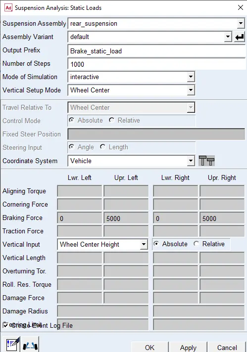
Click on apply the simulation will start.
Brake steer (deg/m):
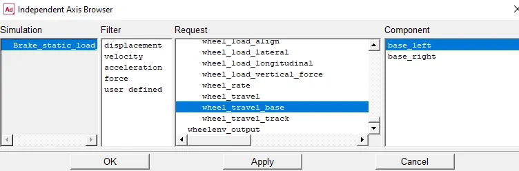
Go to post processor window on the independent axis set wheel base travel click on apply ok as shown,
On the dependent axis toe angle is plotted,
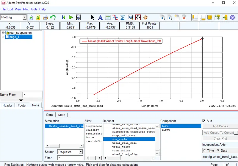
Brake steer = 182 deg/m
From the plot we found that the suspension toes out while braking, hence the car oversteer.
Traction steer:
For this we need to simulate the model again under static traction load of 5000 and name it as 'traction_static_load' with 1000 steps.
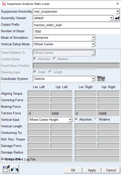
Click on apply and ok. the simulation will start. Once the simulation is completed open the post processing window.
Set the independent axis to data and the select wheel base travel as shown below,
On the dependent axis toe angle is plotted,
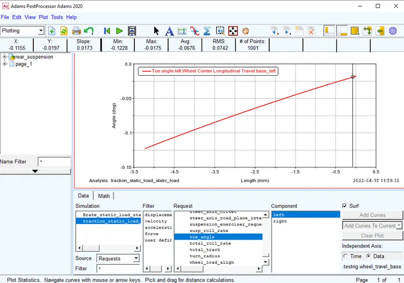
Traction steer = 17.3 deg/m
From the plot we found that the suspension toes out while traction, hence the car oversteer.
Longitudinal wheel center recession under traction:
Here set the independent axis to data and wheel load longitudnal and driving left as shown below, click on apply ok.
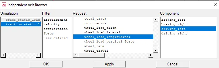
Now for the dependent axis select the wheel base travel left and plot the graph.
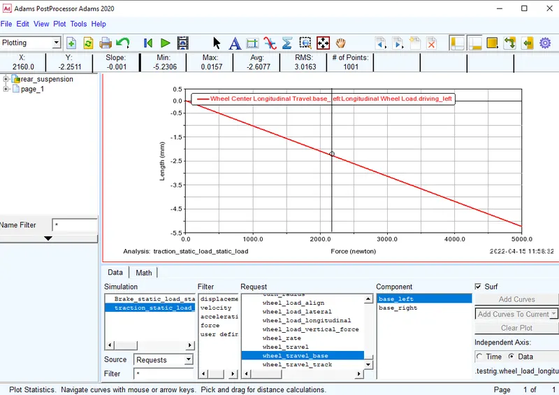
Longitudinal wheel center recession under traction = 1 mm/KN
Longitudinal wheel center recession under braking:
All the arangements are same i.e the independent axis and the dependent axis only the result is plotted for brake simulation and the graph is shown below,
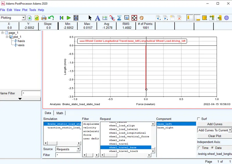
Longitudinal wheel center recession under traction = 0 mm/KN
The trend of longitudanl wheel centre recession under traction and braking varies because the braking force is applied at contact point and the traction force is at centre of wheel and both the forces are opposite to each other.
Lateral force compliance steer:
For this the model is simulated again and now we use cornering force of 5000 with 1000 steps and save it as 'cornering static load' click on apply so that the simulation is started.
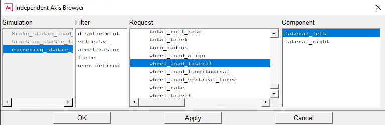
Once the simulation is completed we move to post processing window. Select the independent axis as wheel_load_lateral left and click on apply okas shown below.
Now the dependent axis is set to steer angle and the graph is plotted.
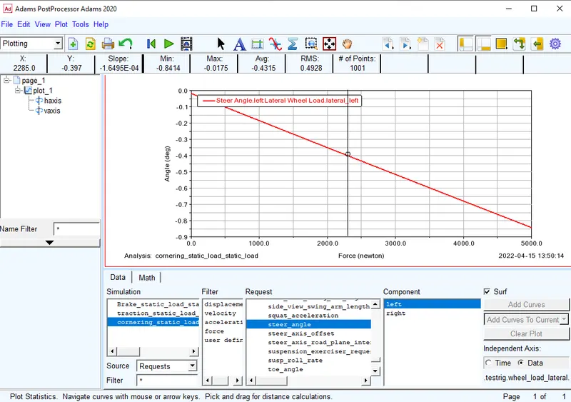
Lateral force compliance steer = 0.1649 deg/KN this causes the rear wheel to toe out producing oversteer effect.
Lateral force compliance camber:
Here the independent axis is set to wheel_load_lateral left and click on apply ok as shown below.
Now the dependent axis is set to camber angle and the graph is plotted.
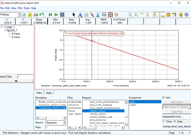
Lateral force compliance camber = 0.396 deg/KN the wheel has negative camber at rear wheel rear producing understeer effect.
Bump steer:
To study bump steer effect parallel wheel travel simulation is runed for 1000 steps and 100mm wheel travel in jounce and rebounce as shown below,
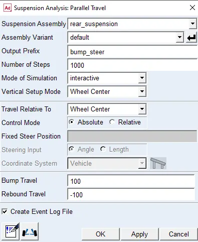
click on apply and ok to start the simulation. Once the simulation is completed open post processing window and select the independent axis to data, wheel travel left and apply.
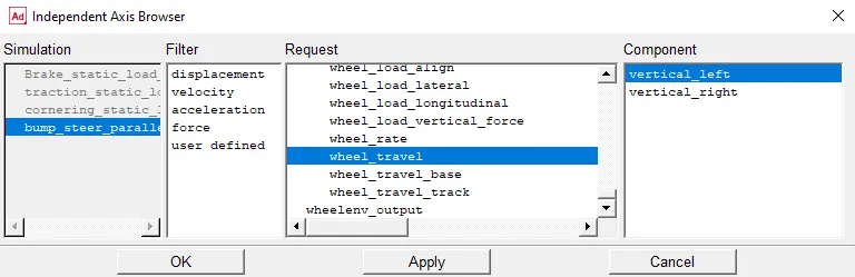
The dependent axis is set to steer ange and the plot is generated,
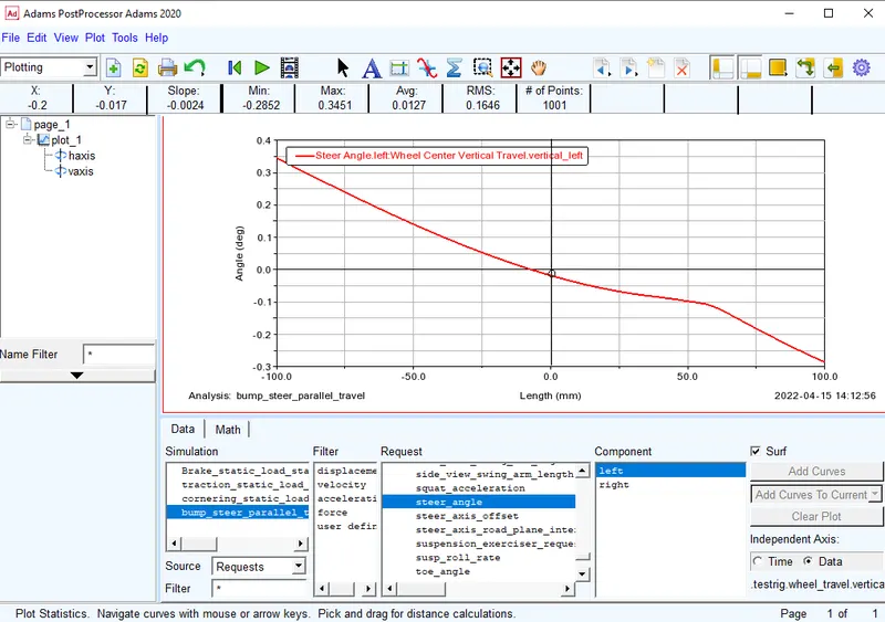
The plot shows that the bump steer is equal to 2.4 deg/m and it will cause toe out at rear wheel resulting in oversteer.
2. Tuning:
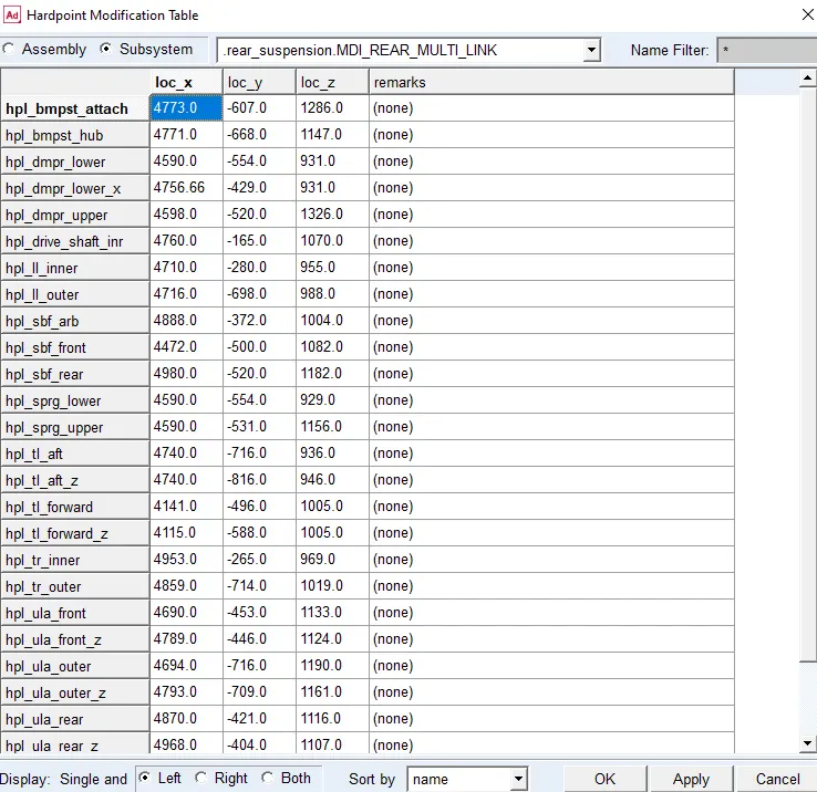
The hardpoints are modified to get the bump steer from 2.4 to 2.6. The initial hardpoints are shown below,
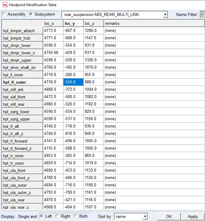
only a single hardpoint is changed as shown below,
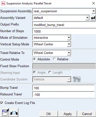
Now the parallel wheel travel simulation is runned name it as modified_bump_steer with 1000 steps and 100 mm in joune and rebounce. Click on apply the simulation will start.
select the independent axis to data, wheel travel left and apply.
The dependent axis is set to steer ange and the plot is generated,
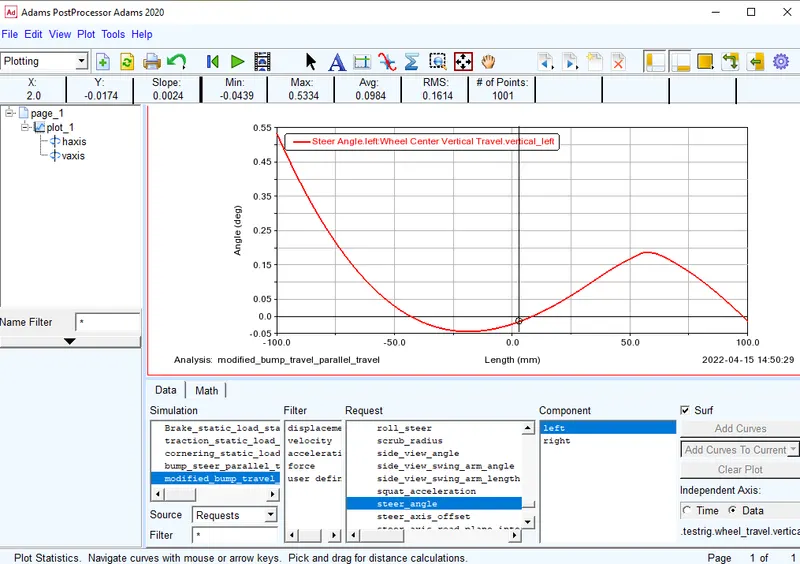
Bump steer of 2.6 deg/mm is achieved and toe out is seen producing oversteer.
Now the bushing is modified, the trailing arm bushing is modified this is modified to change the wheel recession to 500 N/mm. This bushing has large effect on recession.
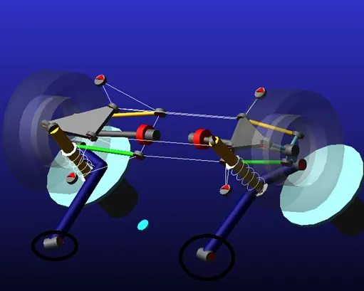
Right click o bushing and select the bushing to modify it.
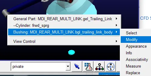
The current bushing is mdi_0001.bus now we search this file take a copy of it and modify the file and use that modify file and run the simulation.
In this bushing file we have changed only the x values,
Original file,
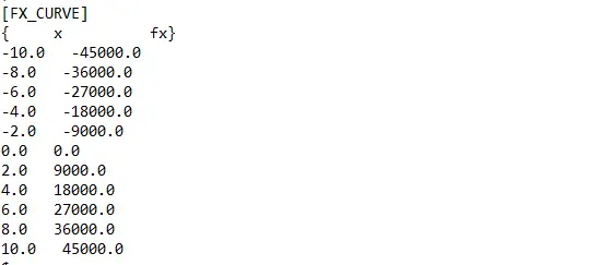
Modified file,
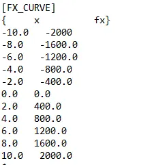
Now right click on bushing and click on modify select this modified file and save the model.
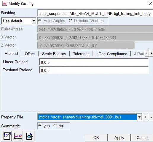
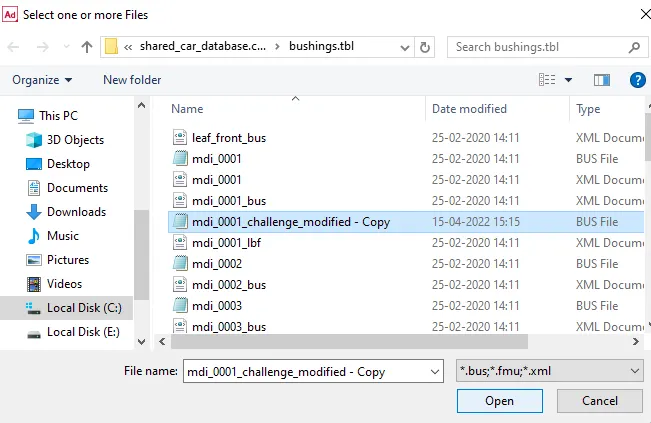
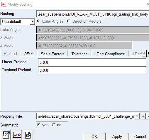
click on apply and ok.
Then the model is simulated again for static traction load of 5000 for 1000 steps and is named as 'traction_modified_static' click on apply. The simulation will start.
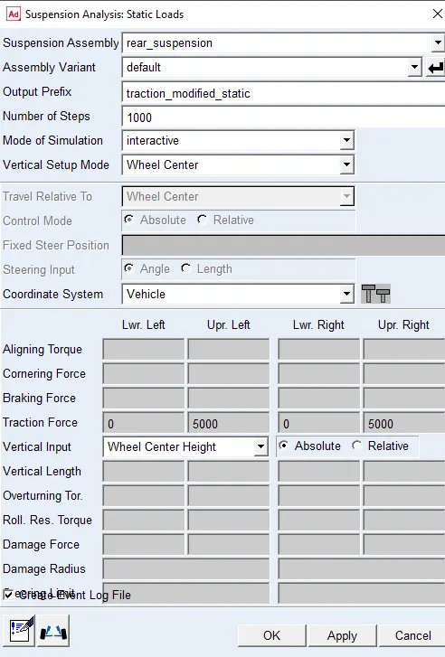
Once the simulation is completed open the post processing window.
Set the independent axis to data and the select wheel base travel as shown below,
On the dependent axis select wheel load longitudnal drining left and plot the graph between them as shown below,
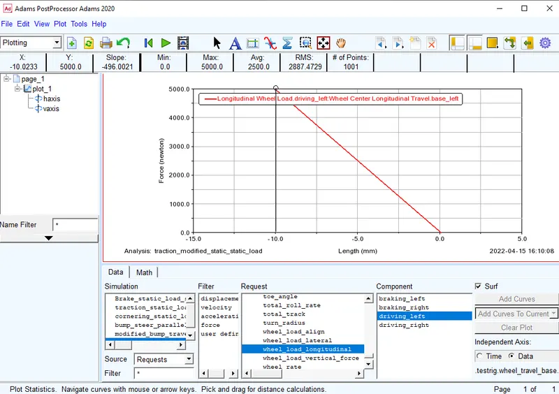
Here the target that the traction wheel centre recession is almost achived to 500 i.e. 497 N/mm.
Now this bushing is restored to the original one, now the next bushing is modified to get the target value of camber compliance.
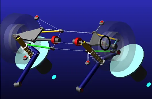
Right click on the bushing and select the bushing and click on modify.
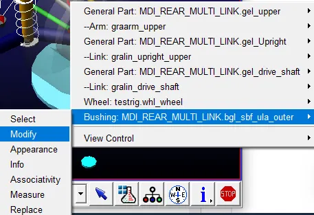
The original bushing file used is mdi_0001.bus
This values are modified in a different file and then that file is given to the bushing.
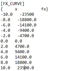
Now load this file in the model and save the model.
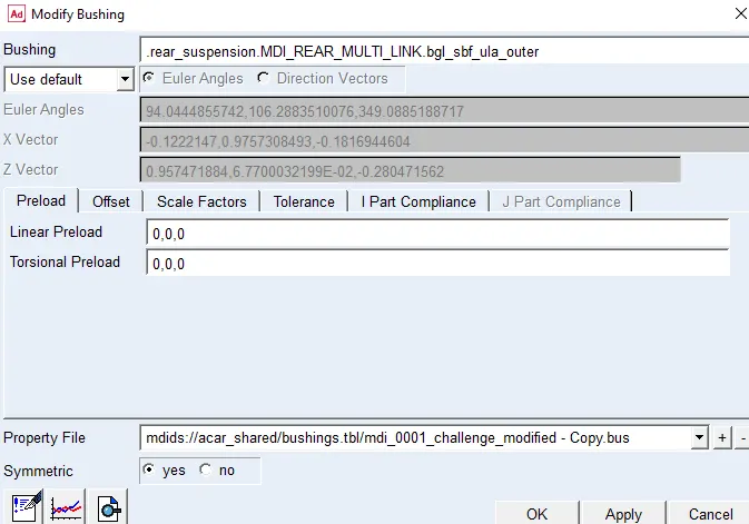
Click on apply and ok.
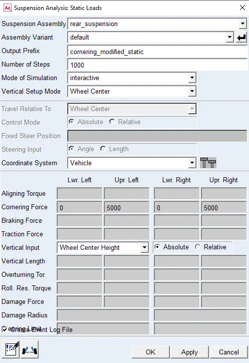
Now we run a simulation for static cornering force with a cornering load of 5000N and name it as 'cornering_modified_static' and click on apply to start simulation.
Once the simulation is completed open the post processing window, set the independent axis to data, wheel travel lateral left as shown below,
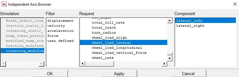
For the dependent axis we select camber angle and plot a graph.
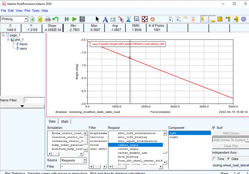
From the above plot we got the camber compliance as 0.451 Deg/KN as per the target is specified.