3D Creation of Celing, Roof, Architectural plan, Structural plan, Sectional view, Elevation view and Camera specific view for a house plan using REVIT
1) Based on the project saved from Week 3, proceed from the First Floor Level. Model a Ceiling from the architecture tab above the walls at the first-floor level.
COMPLETE STEPWISE PROCEDURE TO TO INSERT A CEILING INTO YOUR FLOOR PLAN IN REVIT:
- Open the floor level you want to add a ceiling to from the project browser
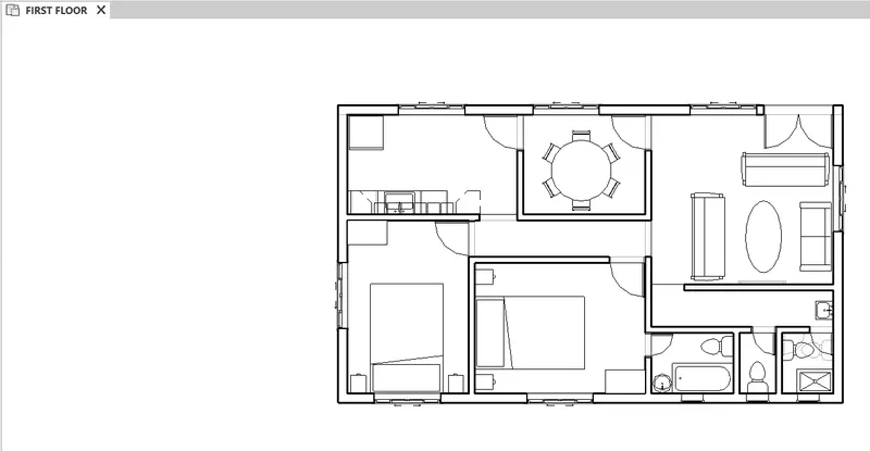
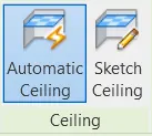
- From the Architectural tab, click on ceiling and go for the sketch ceiling option.
- Then, choose the pick line option and start picking the ceiling boundary as per your floor plan and click on the green tick button available in the upper ribbon.
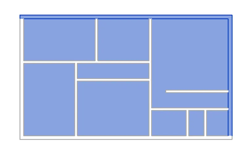
- And that's it. You can go to the 3d-view to look at your ceiling. And you can also adjust its settings from the properties panel.
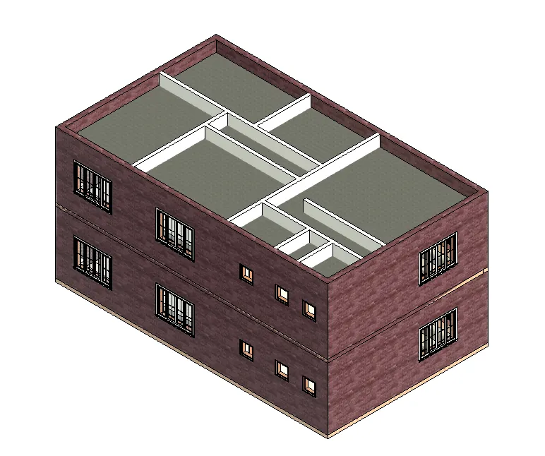
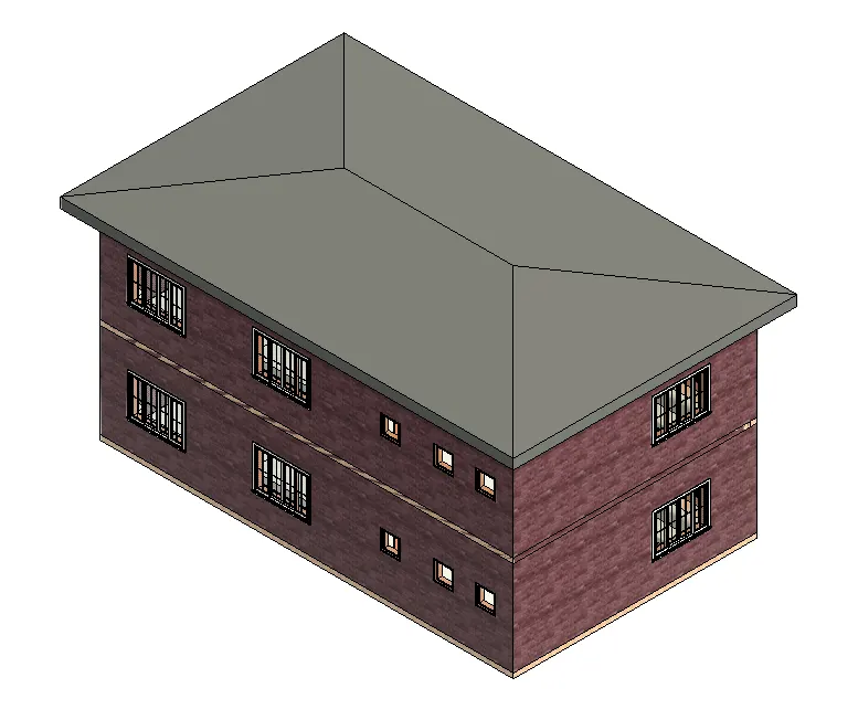
2) Model a roof above the ceiling by selecting the footprints of the ceiling. Using the adjustment toolbars appearing on-screen adjust the roof slope to 10 degrees.
COMPLETE STEPWISE PROCEDURE TO MODEL A ROOF ON TOP OF THE BUILDING IN REVIT:
- From the Architectural tab, click on "Roof" and pick the "Roof by Footprint" option. Then, select the pick line option and set up the roof boundary on top of the building.
- Click on the green tick arrow and finish up the roof modeling.
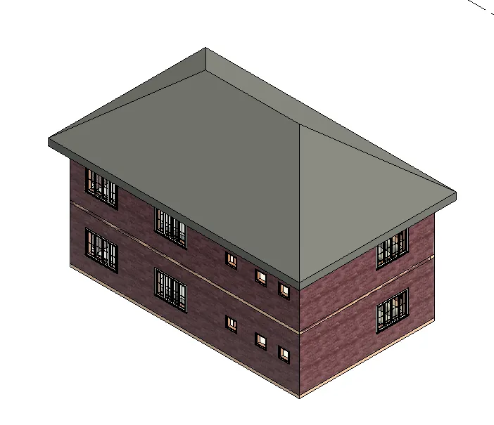
- Give your roof an appropriate slope.
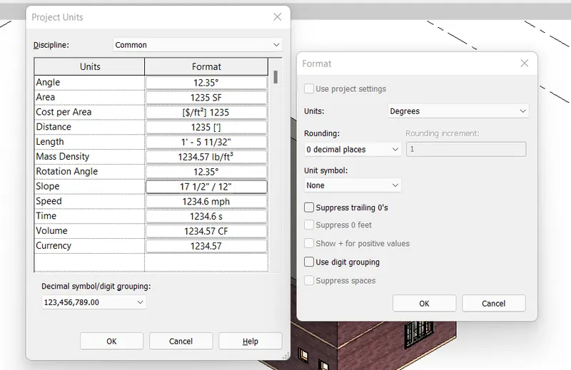
- First, type in "UN" and set up the slope units as degrees.
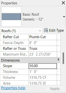
- Then, select your roof and from the properties panel, go to dimensions and change slope to 10 degrees which is suitable both aesthetically as well as functionally.
- FINAL OUTPUT
3) Using the file saved from weeks 2 to 4, create plan views for ground floor level and first-floor level including all the walls, floors, and components. Separate them to
architecture and structural plans
a. Architecture plan must have walls, floors, and all the components placed within the building
b. Structure plan must have details of only walls, floors, and columns.
COMPLETE STEPWISE PROCEDURE TO DIFFERENTIATE THE STRUCTURAL PLAN FROM AN ARCHITECTURAL ONE IN REVIT:
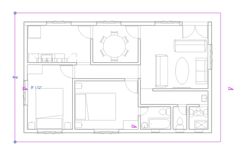
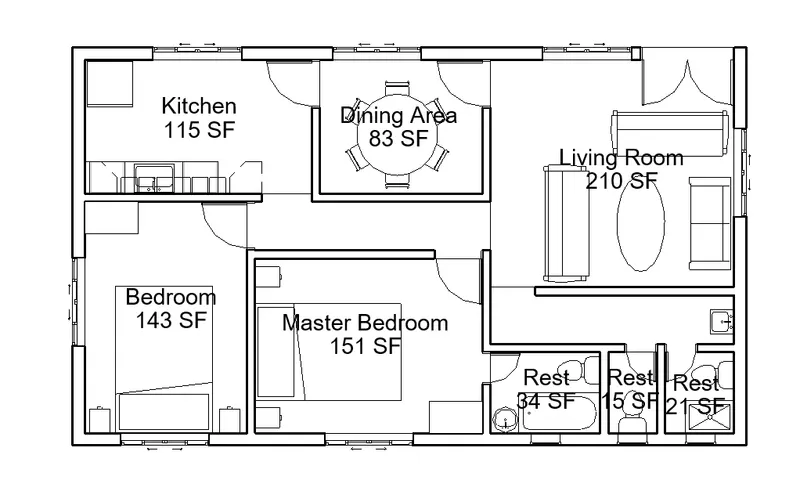
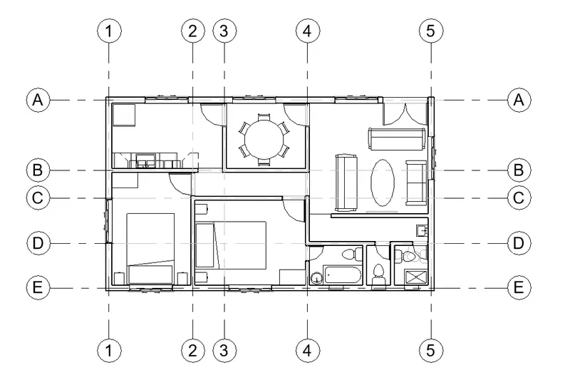
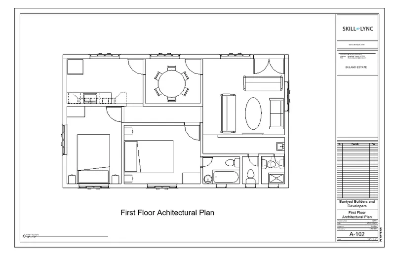
- Architectural plans: Architectural plans are those that contain every information regarding how the building looks from the outside and the inside. These plans are supposed to showcase the placement of different components like furniture, seating arrangement, location of TV, fridge, etc. And when you open an Architectural template in Revit, the plans you create are by default Architectural ones. Moreover, there is a way to separate a structural plan from your default Architectural plan which is discussed further. But a typical Architectural building plan is inserted below to make things more clear.
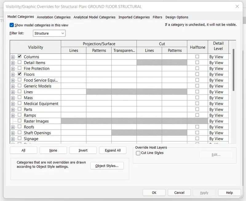
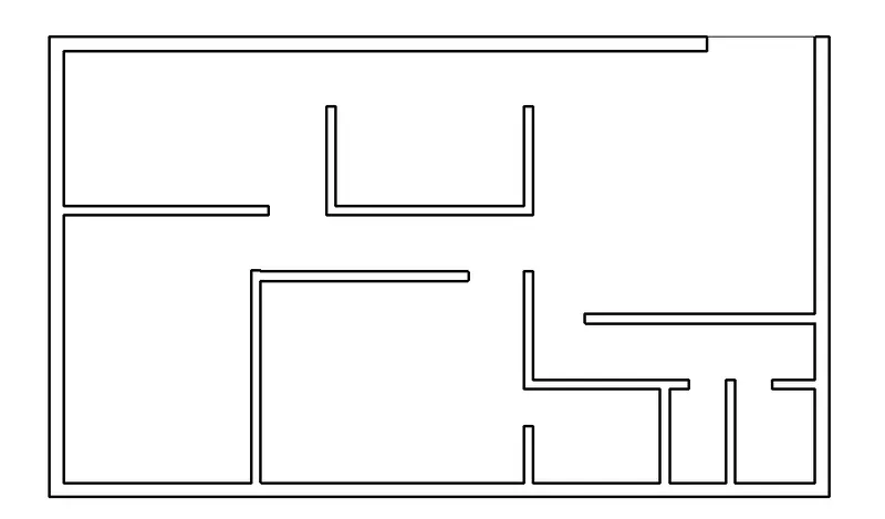
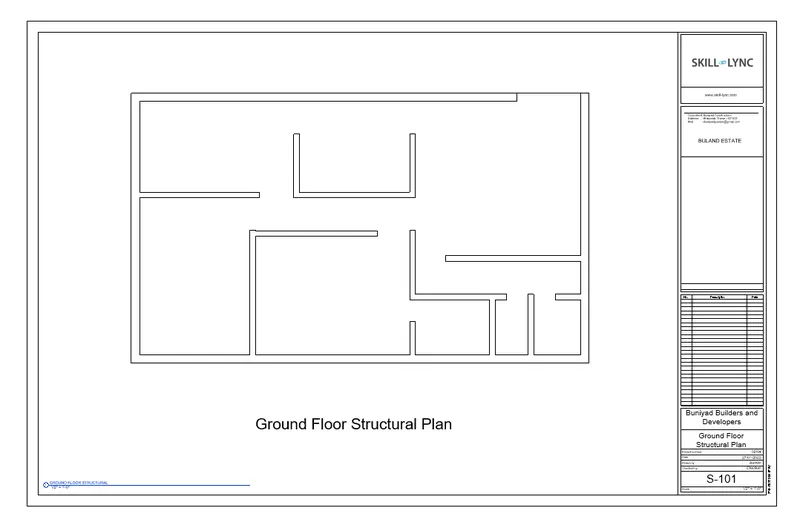
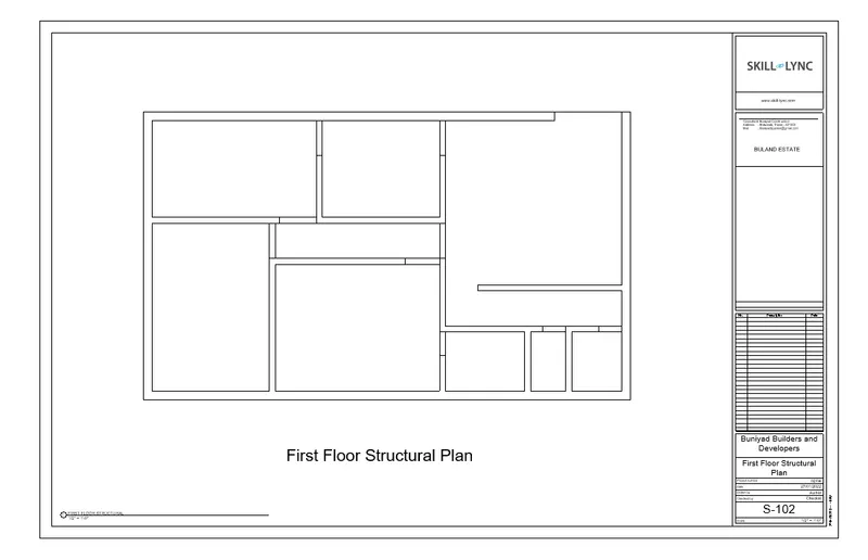
- Structural Plans: Structural plans are supposed to help analyze the overall functioning of the building under service loads. And for the same reason, it only showcases the members that are going to add load significant loads on the structure like slabs, beams, columns, and walls. And to separate the structural plan in Revit, go to view -> plans -> Structural plan. Now, the structural version of your floor plan will be displayed. And to control what you want to be displayed in a particular plan, you can go to visual graphics by typing "VV" or "VG" and deselect the elements you don't need in the structural plan. The same is showcased below:
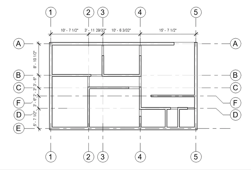
4) Using annotate toolbar add dimensions to all the walls and floors with reference to the longitudinal and transverse grids created in the project file
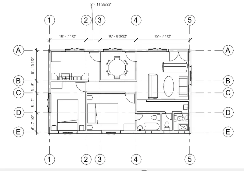
a. The architecture plan dimensions include details on where the components are placed within the buildings with relation to grids. Overall dimensions are sufficient for architecture plans.
COMPLETE STEPWISE PROCEDURE TO ADD GRIDS AND DIMENSION YOUR PLANS AS PER THOSE GRIDS IN REVIT:
- Create grids cutting through the center of your walls. (Both longitudinal and transverse)
- To create grids, you can type GR.
- Then, carefully place all your transverse and longitudinal grids passing through wall centers.
- You can either draw each grid manually or use offset and then make use of the align tool to put them in place.
- Use dimension tool to locate different elements from grids
- Type in "DI" to invoke dimensions.
- Select entire wall method as opposed to the individual references.
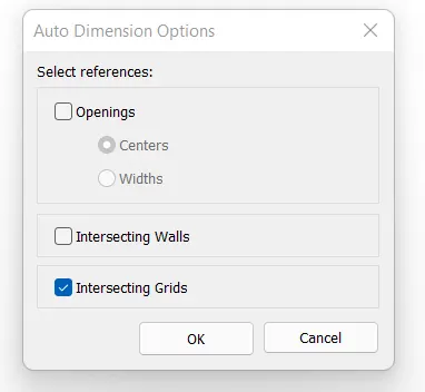
- Go to options and select intersecting grids.
- Start dimensioning the grids.
Dimensions as per Architectural plan
Dimensions as per the structural layout
5) Create a sheet template from the view tab and adjust the parameters on the sheet to add appropriate views.
COMPLETE STEPWISE PROCEDURE TO CREATE A SHEET TEMPLATE IN REVIT ADD UP THE DESIRED VIEW INTO IT:
- Open the view on your Revit Screen which you want to create the sheet of and crop the desired view from the crop tool.
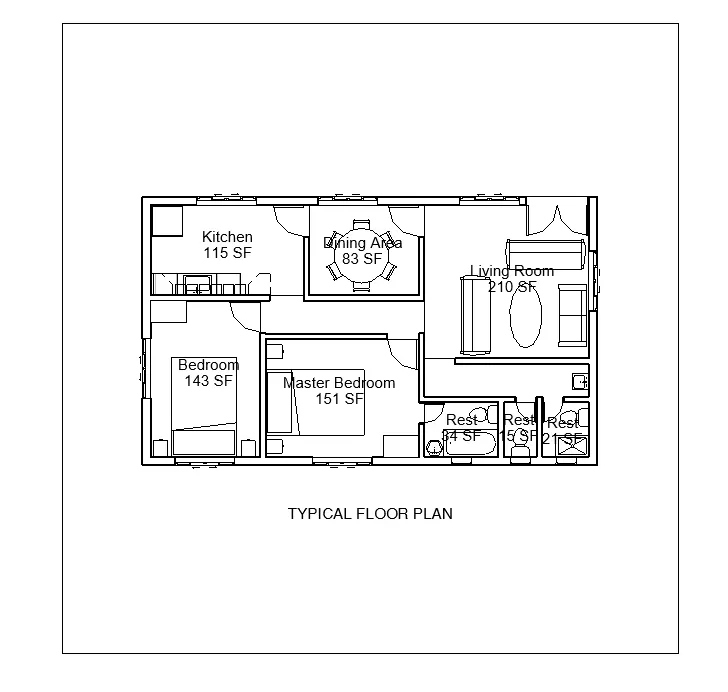
- Now from the view tab, click on the sheet to create a new sheet. At the same time, choose the proper sheet size from the list given.
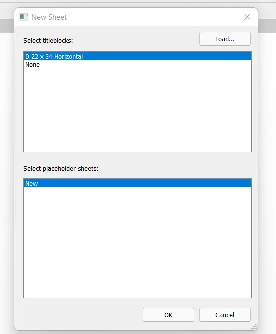
- Once you select the sheet dimensions, a new sheet window will open up in Revit.
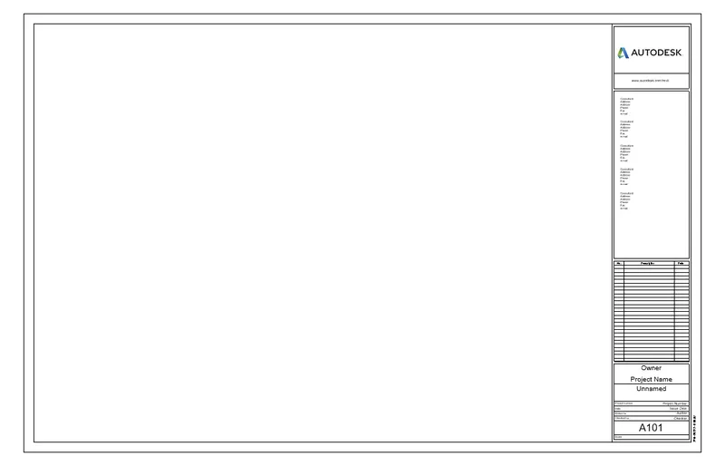
- Now to edit its parameters, double click on the sheet and do the necessary changes.
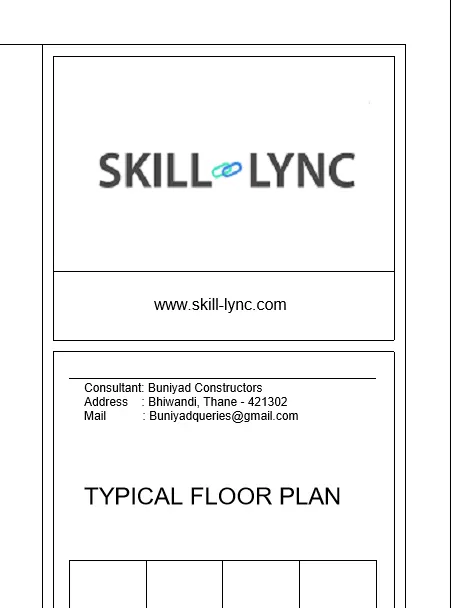
- Now, load the sheet into your current project and edit its name, number, and other details.

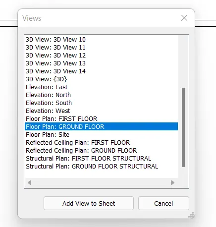
- Click on the view ribbon and add your desired view from the list into the sheet. You can also drag and drop the view from the project browser.
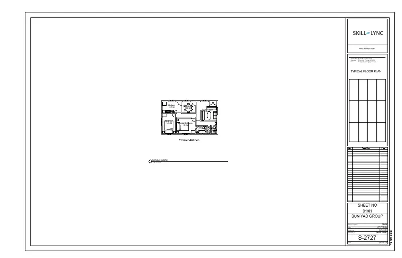
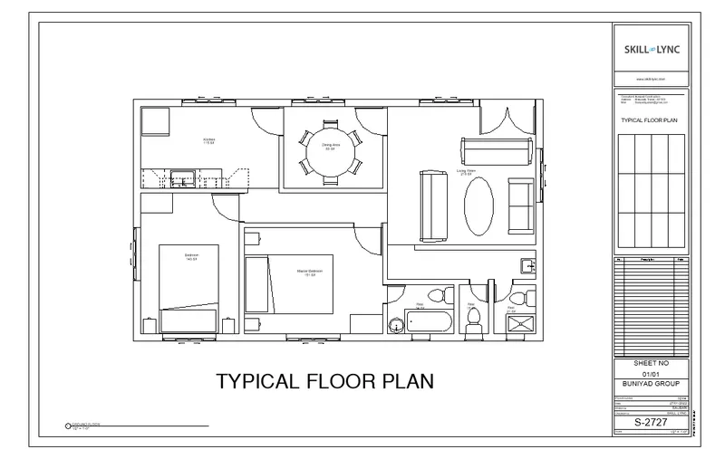
- Adjust the view scale from the properties panel as per requirements.
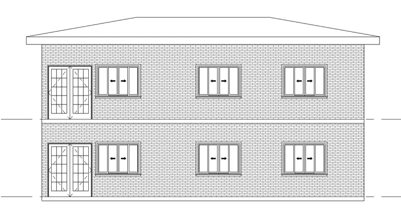
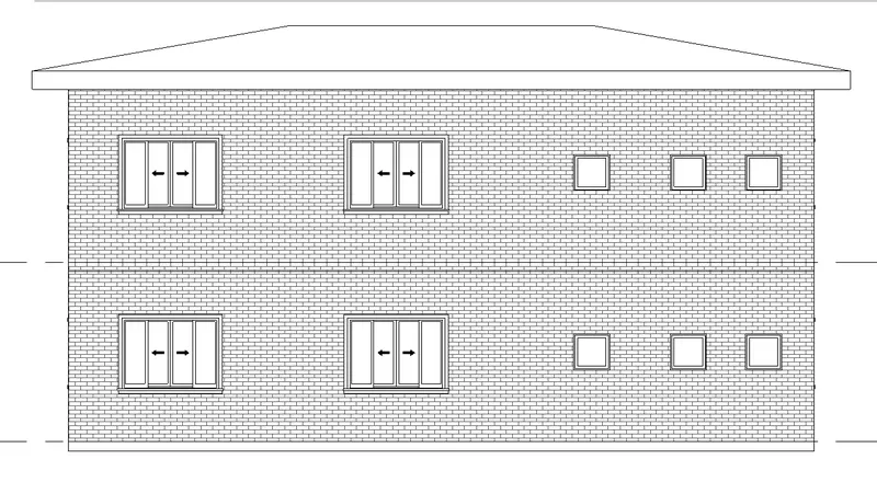
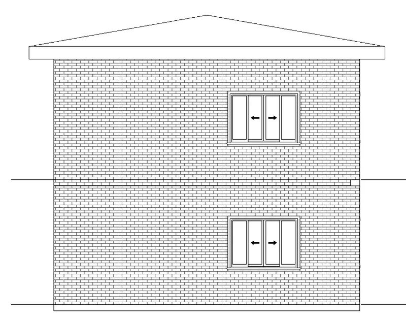
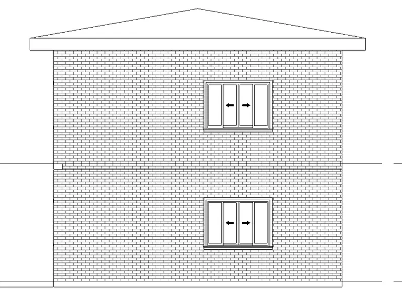
6) Using the elevation tab create the elevation views, looking at your building from East, North, South, and West.
COMPLETE STEPWISE PROCEDURE TO CREATE THE NORTH, SOUTH, EAST, AND WEST ELEVATIONS OF YOUR BUILDING IN REVIT:
- Creating an elevation view in Revit is really simple.
- All you have to do is just make use of the built-in Revit elevation bubbles in the correct manner.
- You can create and place a new elevation bubble from the view tab.
- And then, double-click on the triangle attached to the bubble to generate the elevation view precisely in front of that particular triangle.
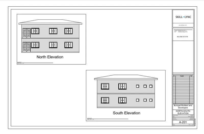
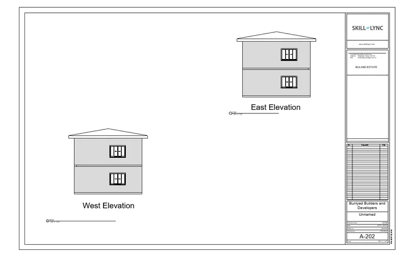
Thus, the same method is used and all four directional views of our building are generated which are inserted below:
NORTH ELEVATION
SOUTH ELEVATION
EAST ELEVATION
WEST ELEVATION
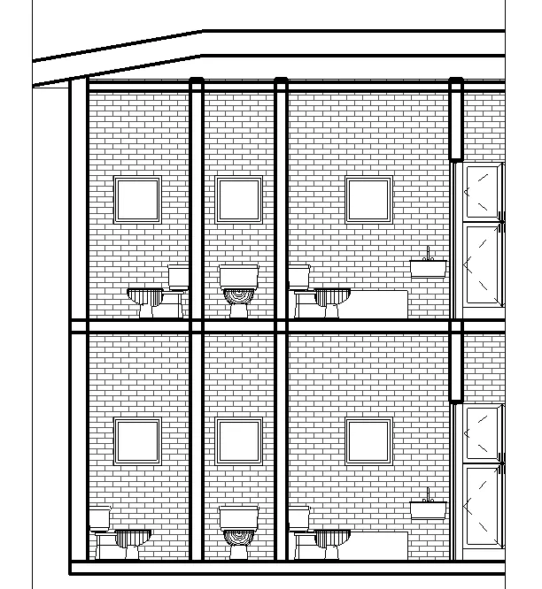
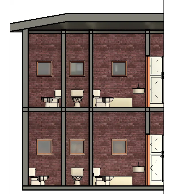
7) Produce section cut through each room either cutting across longitudinally or in a transverse direction.
COMPLETE STEPWISE PROCEDURE TO CUT SECTIONS THROUGH YOUR REVIT MODEL:
- Creating sections is the same as creating elevations with a small variation.
- But unlike elevations, you have to set up a distance to which you want your sections to cut.
- From the view tab, click on the section and create the section in your plan like you draw the walls.
- Now, you can flip the section to make it cut from the other side.
- Once satisfied with the section, you can double click on the bubble triangle to open up the sectional views.
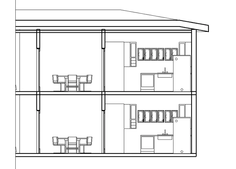
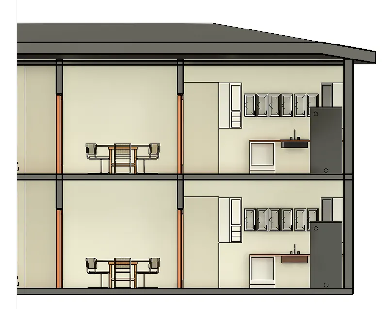
Thus, the same method is adopted and the following sectional elevations of the building are generated.
LIVING ROOM SECTION
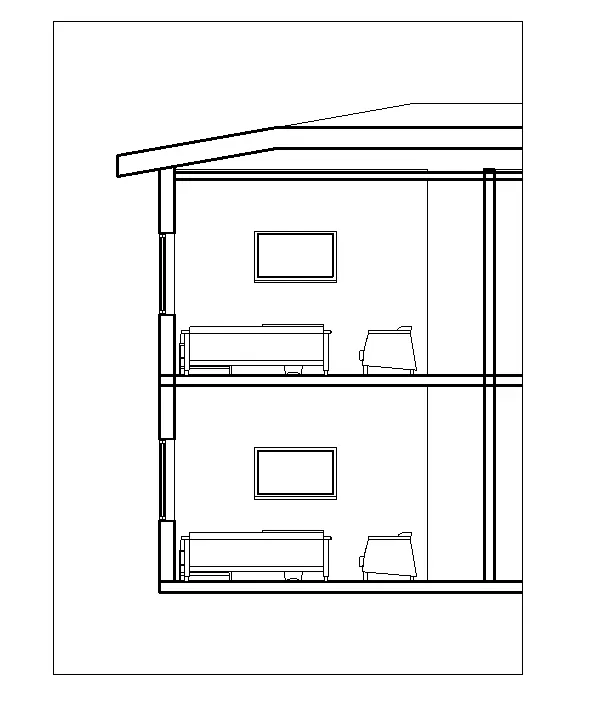
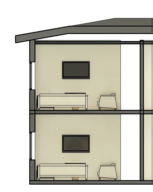
KITCHEN PLUS DINING AREA
BEDROOM
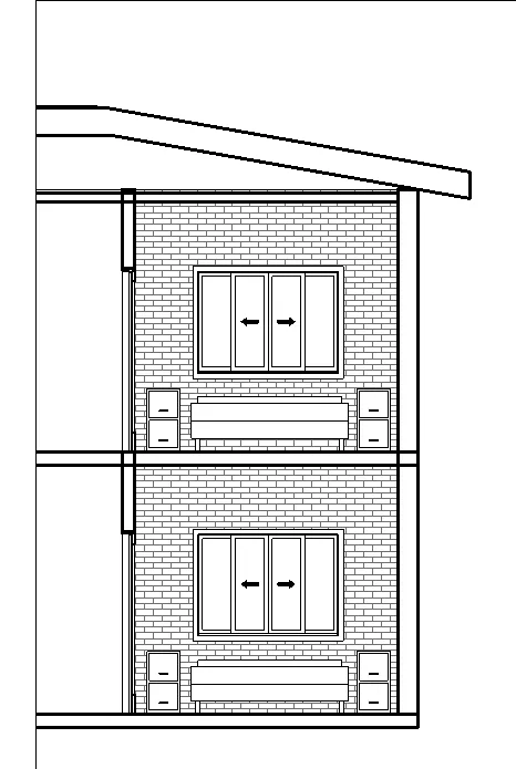
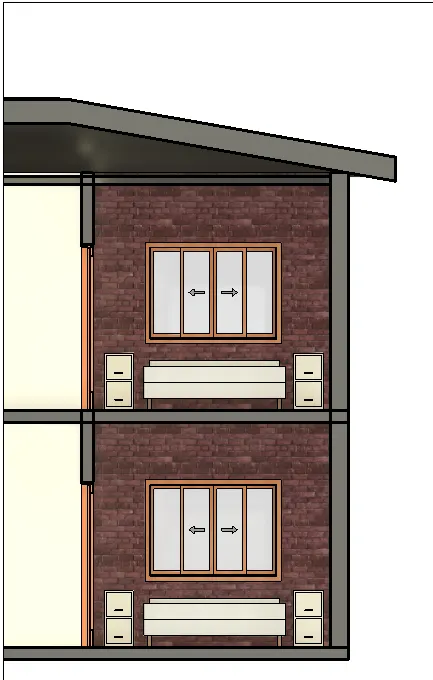
MASTER BEDROOM
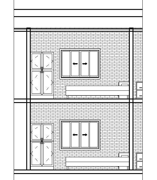
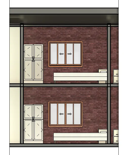
WASHROOMS
8) Classify the views, Plan Views, Section Views, and Elevation views to either Design or Documentation category using Properties browser.
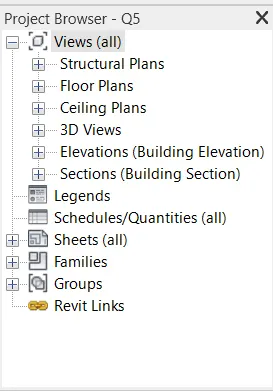
Views in Revit are by default classified into different categories like floor plans, structural plans, ceiling plans, sections, elevations, 3d views, etc. At the same time, Revit also allows you to add up your own classifications based on your project requirements in order to improve the workflow. Hence, you can invoke any one of the classified views at any point in time. The list of typical Revit classifications is inserted below:
9) Using the sheet template produced create multiple sheets as follows
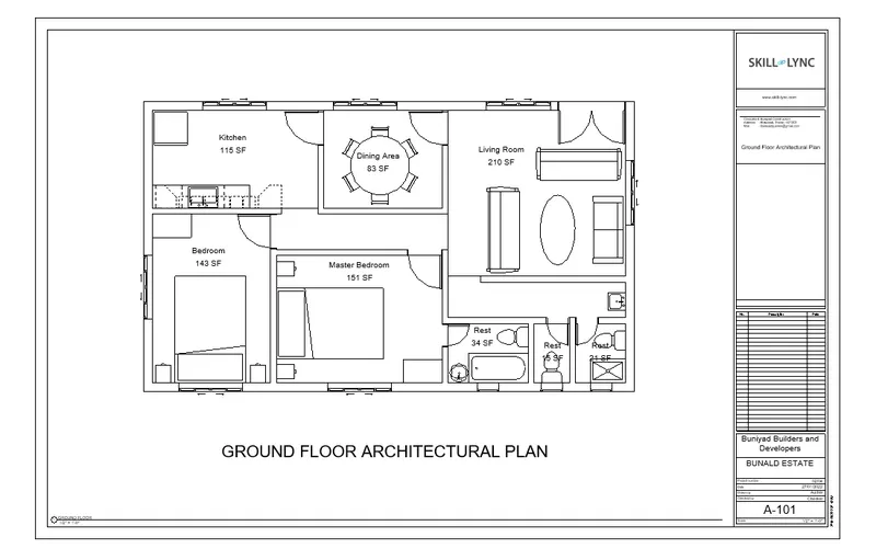
a. A 101- Ground Floor Architecture Plan
b. A 102- First Floor Architecture Plan
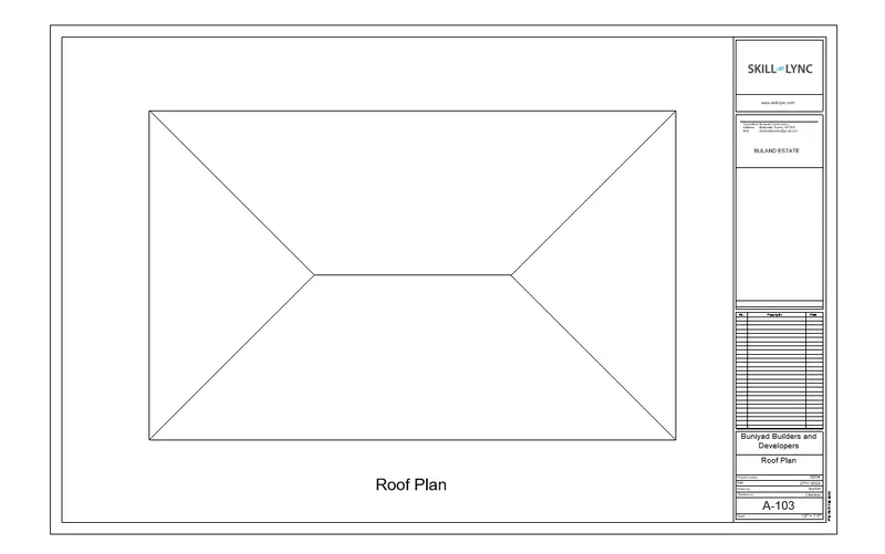
c. A 103- Roof Plan
d. S 101- Ground Floor Structural Plan
e. S 102- First Floor Structural Plan
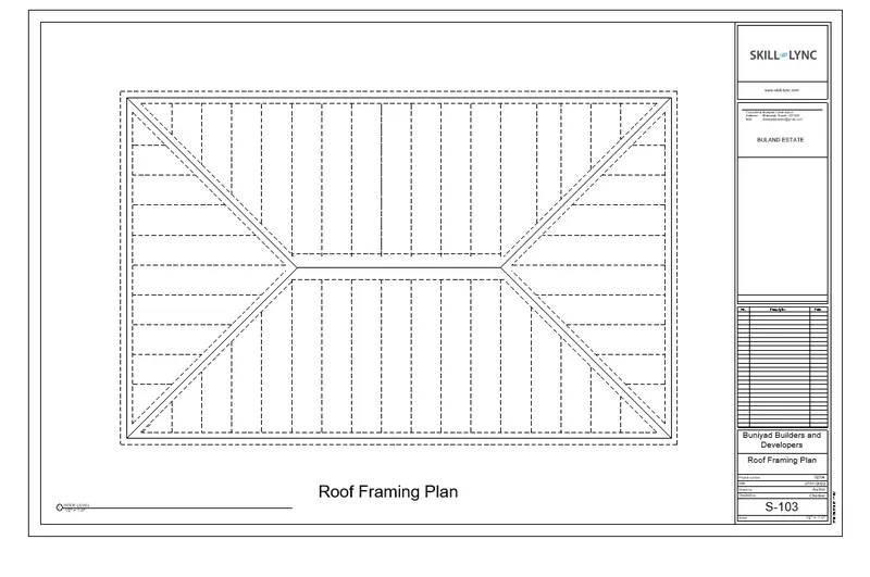
f. S 103- Roof Framing Plan
g. A-201- North-South Elevations
h. A-202- East-West Elevations.
As the sheet template has already been created into our project, and the complete stepwise procedure to set up sheet views has also been covered. We are going to insert the mentioned views directly below:
A-101
A-102
A-103
S-101
S-102
S-103
A-201
A-202
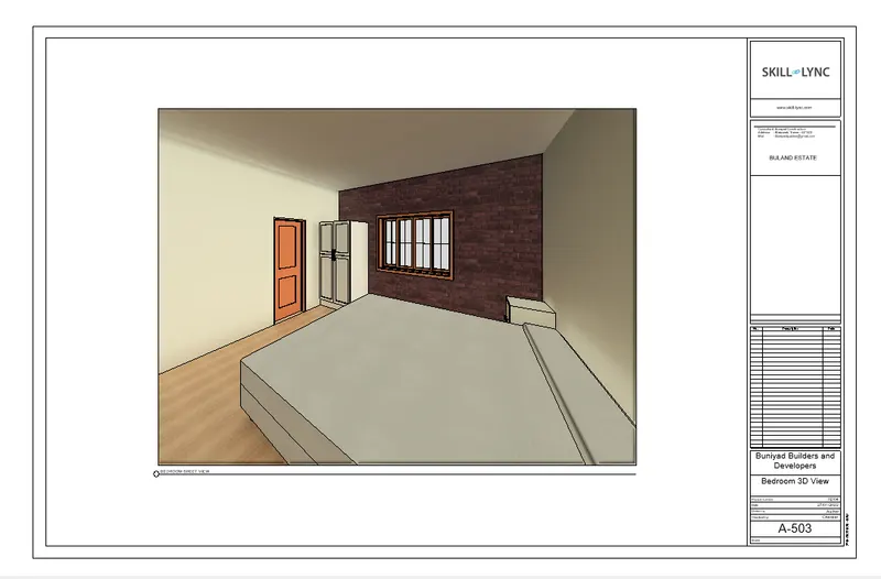
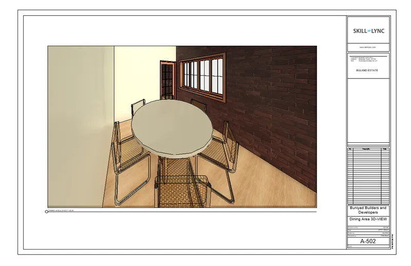
10) Create a camera-specific view or a 3D view in each room ( living, dining, bedroom). Based on the views create a new set of sheets starting A-501 (you can add as many sheets after, 502, 503.. n)to place the 3D view images. Produce the sheets as a part of project drafting.
A-501
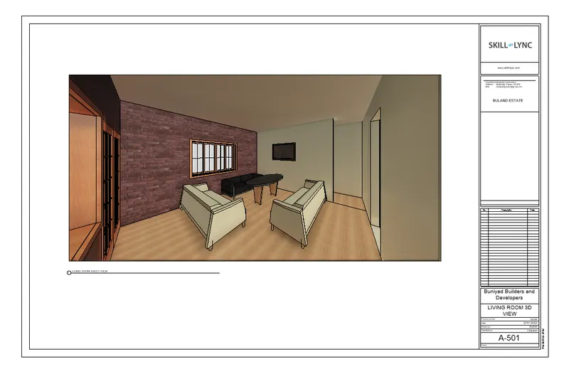
A-502
A-503