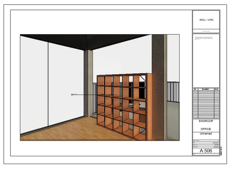
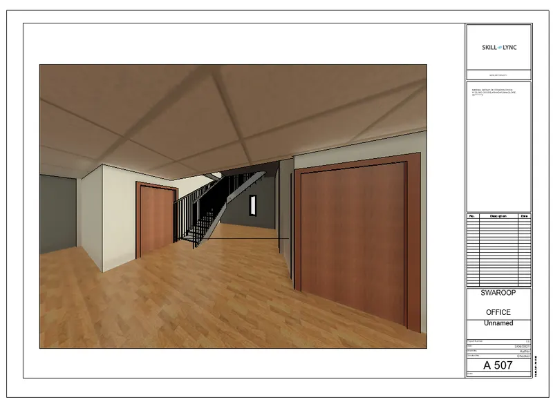
3D Creation of Celing, Roof, Architectural plan, Structural plan, Sectional view, Elevation view and Camera specific view for a house plan using REVIT
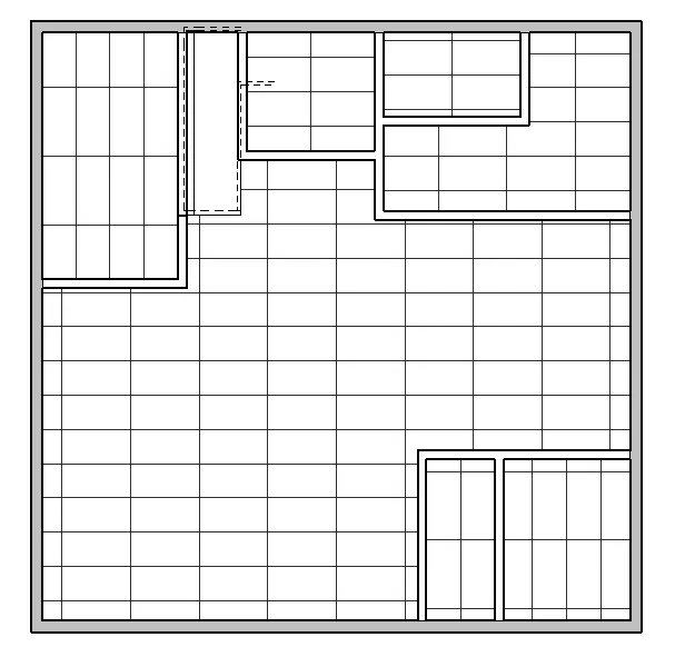
1) Based on the project saved from Week 3, proceed from the First Floor Level. Model a Ceiling from the architecture tab above the walls at the first-floor level.
AIM: TO create ceiling from architecture tab above the walls at the first floor level.
INTRODUCTION:
- A part of a building which encloses and is exposed overhead in a room, protected shaft or circulation space.
- It helps us to create an enclosure and separation between spaces.
- They help to control the diffusion of light and sound around a room, and help prevent the passage of sound between rooms.
- They protect and concealed the electrical and plumbing systems above it.
PROCEDURE:
- select the ceiling option from architecture toolbar.
- set the ceiling view as first floor.
- click on the area need to add ceiling.
- edit using modify toolbar-edit the boundry option for opening in staircase ceiling.
RESULT:
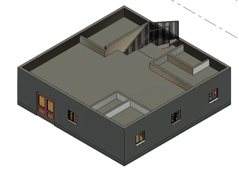
2) Model a roof above the ceiling by selecting the footprints of the ceiling. Using the adjustment toolbars appearing on-screen adjust the roof slope to 10 degrees
AIM: To model a roof above the ceiling using footprint option in roof and setting the roof slope as 10 degree.
INTRODUCTION:
- Roof is defined as covering of the top of a building, serving to protect against rain, snow, sunlight, wind, and extremes of temperature.
- Roofs have been constructed in a wide variety of forms—flat, pitched, vaulted, domed, or in combinations—as dictated by technical, economic, or aesthetic considerations.
- In revit roof can be doen using footprint,tracing the path of wall.
- Roof can be done by extrusion in 3d view/section view.
- Roof by Face is creating a non-vertical roof.
PROCEDURE:
- Now create an additional level 3- and rename it has roof.
- select roof by extrusion option and select pick boundry lines.
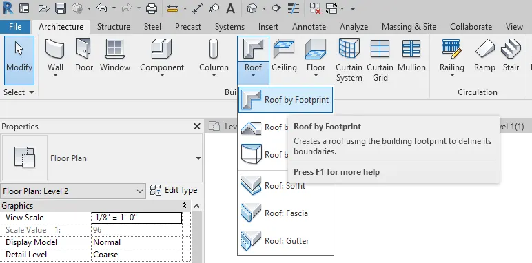
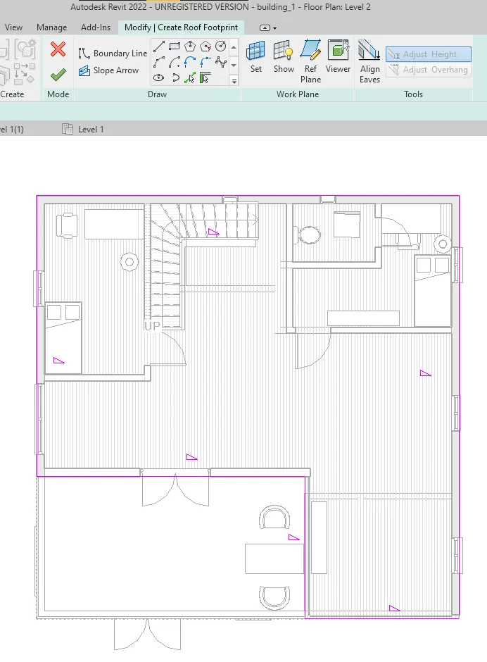
- select the wall lines in level 2 and click ok.
- select the roof,in property browser-set the slope as 10 degree-apply.
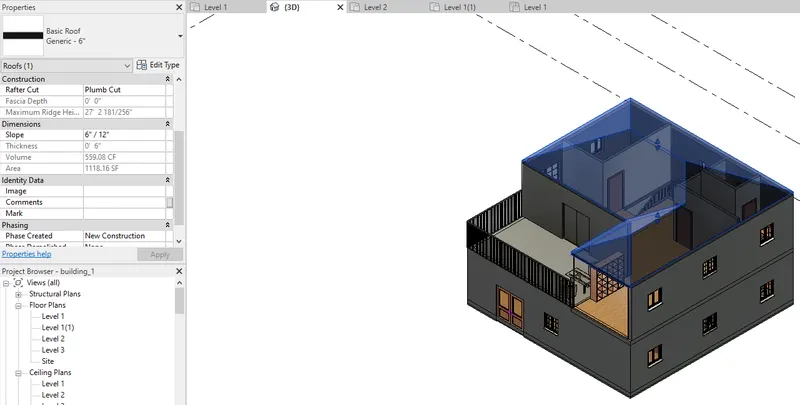
RESULT:
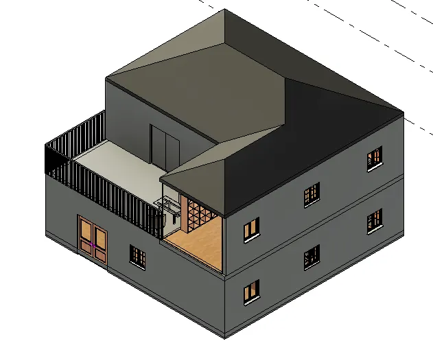
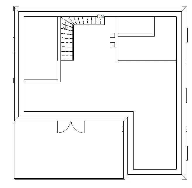
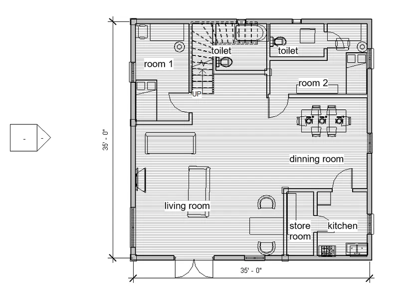
3) Using the file saved from weeks 2 to 4, create plan views for ground floor level and first-floor level including all the walls, floors, and components. Separate them to
architecture and structural plans
a. Architecture plan must have walls, floors, and all the components placed within the building
b. Structure plan must have details of only walls, floors, and columns
AIM: To create plan view for architectural and structural separately.
INTRODUCTION:
- Two-dimensional views provide a traditional method for viewing a model.
- These views include floor plans, ceiling plans, and structural plans.
- In revit this plan can easily be separated and saved in view portal for easy access.
PROCEDURE:
- Open the file created in week 2 of a residential G+1 storey building.
- go to view option and select plan view.
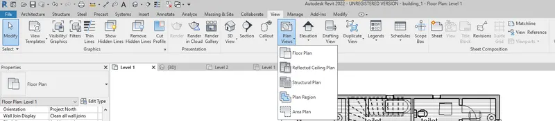
- select floor plan,in the display click on level 1.
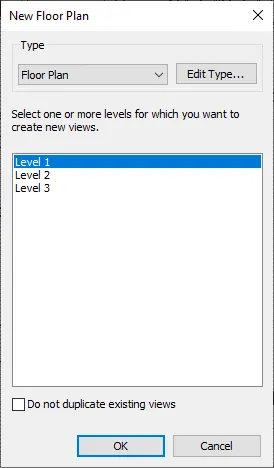
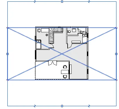
- crop the region be to displayed,rename the floor view as first floor.
- simialry repeat the same for second floor view also.
- now for structural view,go to view-plan view and select strcutural plan.
- it display only structural plan .crop the region to be displayed.
RESULT:
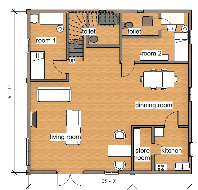
FLOOR VIEW-
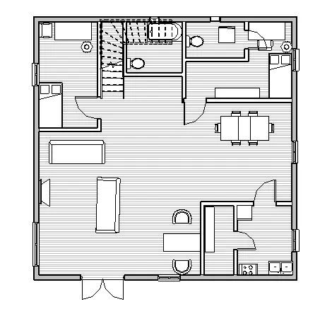
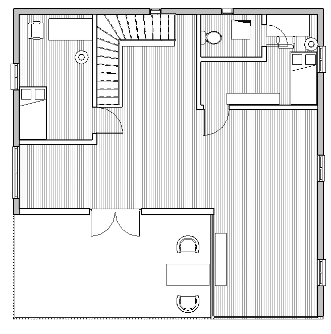
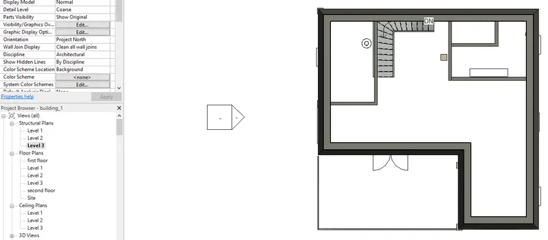
STRUCTUAL VIEW-
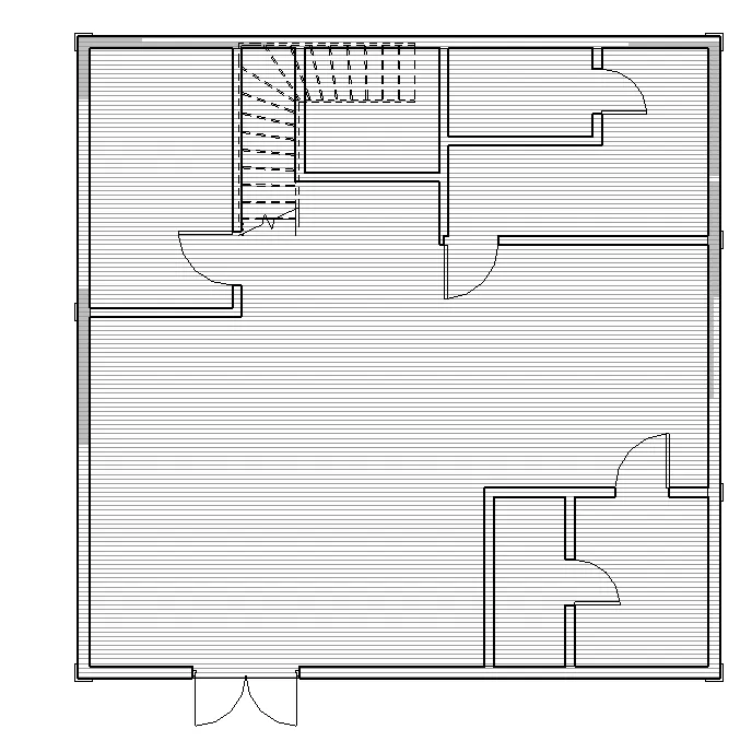
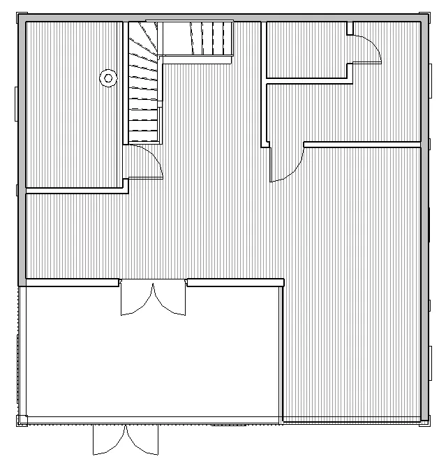
4) Using annotate toolbar add dimensions to all the walls and floors with reference to the longitudinal and transverse grids created in the project file
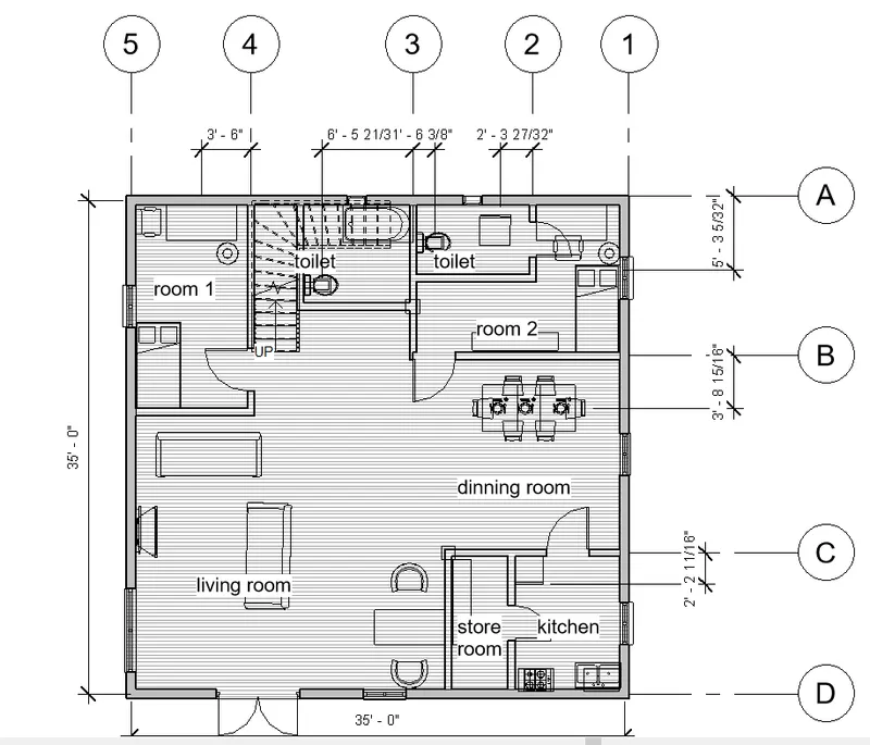
a. The architecture plan dimensions include details on where the components are placed within the buildings with relation to grids. Overall dimensions are sufficient for architecture plans
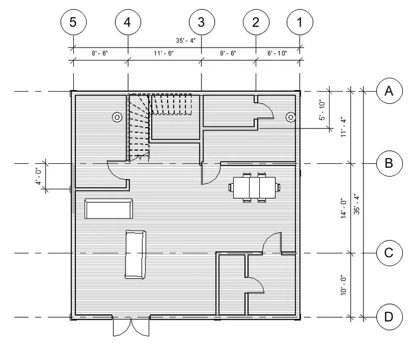
b. The Structure plan dimensions must include details on the position of all the walls and interior walls with reference to grids. Locate all the framing components of the building with reference to a fixed point using Structural plans
AIM: To add dimensions for both architecural components and atructural components using grid as reference.
INTRODUCTION:
- Grid lines are added to a model to create a reference and framework for the design.
- You can drag their extents in elevation views so that they do not intersect level lines. This allows you to determine whether grid lines appear in each new plan view that you create for a project.
- Grids can be straight lines, arcs or multi-segmented.
- Dimension measure such as alinged,linear,diamter,angle etc.
PROCEDURE:
- Select the grids and create longitudinal and transverse grids.
- name the longitudinal grids in numbers and transverse grids in alphabets.
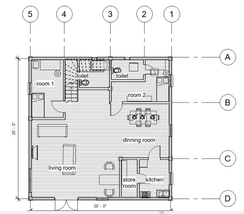
- now select the alined dimension from annotate toolbar.
- keep the cursor on grids and click ok.
- repeat the same for structural plan also.
RESULT:
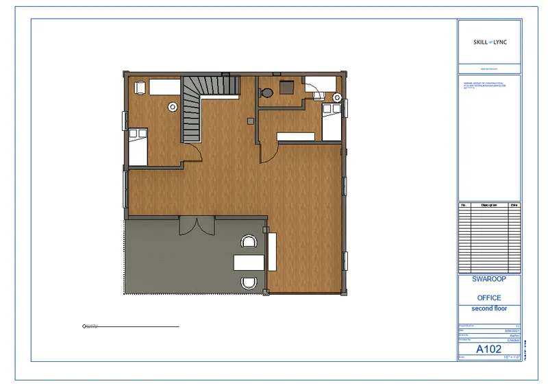
5) Create a sheet template from the view tab and adjust the parameters on the sheet to add appropriate views
AIM: To create a sheet template for floor views.
INTRODUCTION:
- In Revit you create a sheet view for each sheet in the construction document set. You can then place multiple drawings or schedules on each sheet view.
- Create views on a project template before you start building the model to streamline the project documentation process.
PROCEDURE:
- to create sheet template,first create floor view of first and second floor.
- go to view toolbar,select sheet.

- select a template format and click ok.
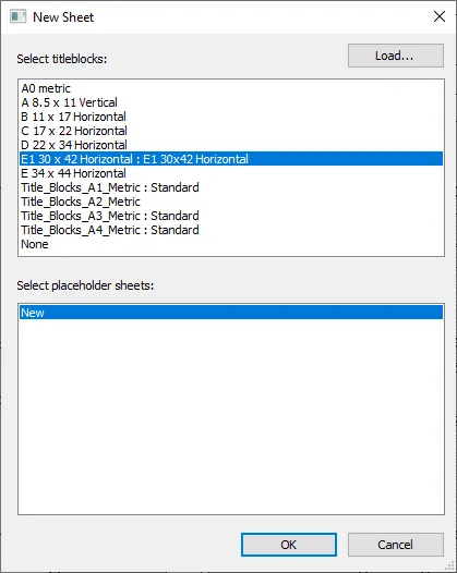
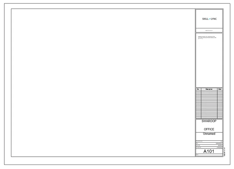
- click on the titleblock to edit and select edit family.
- edit the information to present project stauts and click ok.
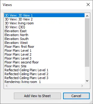
- to place the floor view,go to view toolbar again and click on view option which is next to sheets.
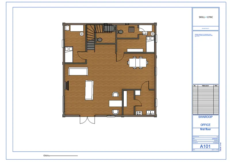
- select the first and second floor view and place in the template.
- adjust the view with help of scale annotate.
- after placing the floor view ,double click to lock the view.
RESULT:
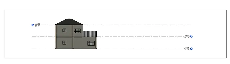
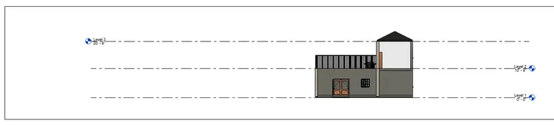
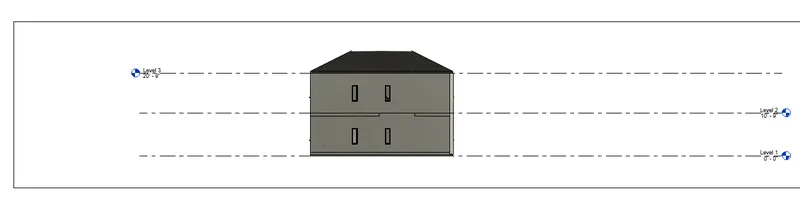
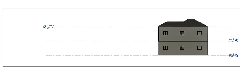
6) Using the elevation tab create the elevation views, looking at your building from East, North, South, and West
AIM: To create elevation views of building from east,north,south and west.
INTRODUCTION:
- Elevation views are part of the default template in Revit.
- When you create a project with the default template, 4 elevation views are included: north, south, east, and west.
- It is in elevation views where you sketch level lines.
- For each level line that you sketch, a corresponding plan view is created.
PROCEDURE:
- go to view toolbar and select elevation view option.

- place the view point in east direction,view will be created.
- rename the view as east-1.
- simialry repeat the same for remaning three sides also.
RESULT:
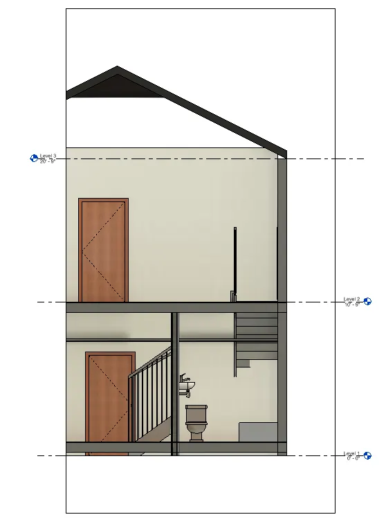
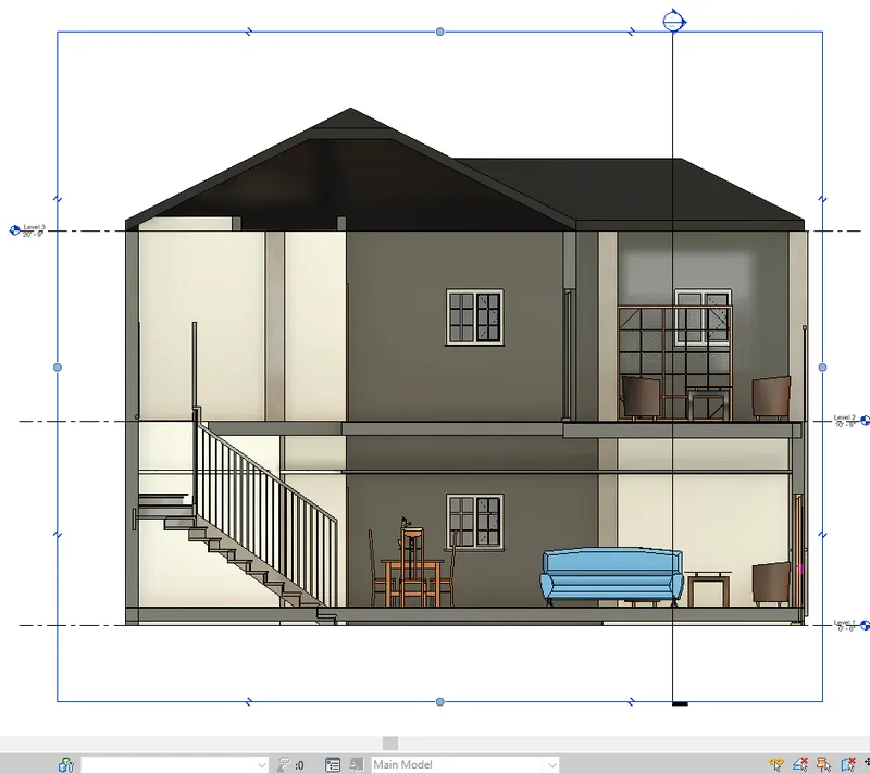
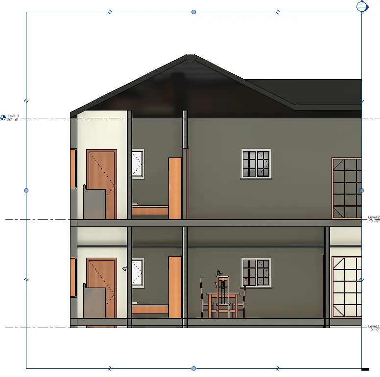
7) Produce section cut through each room either cutting across longitudinally or in a transverse direction
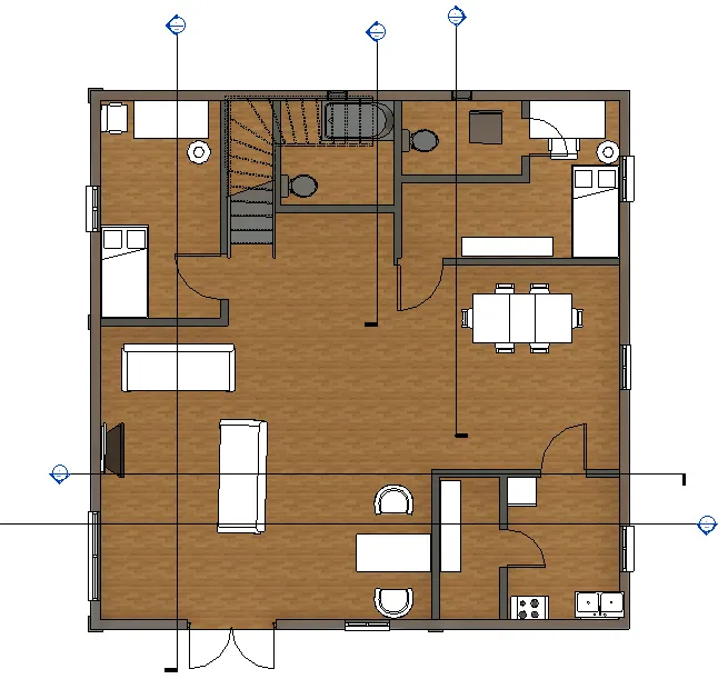
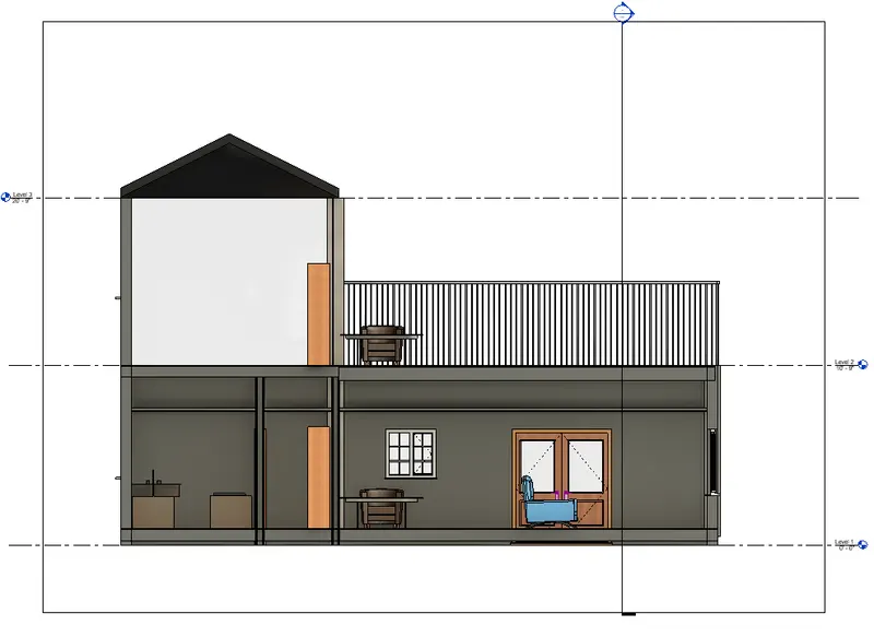
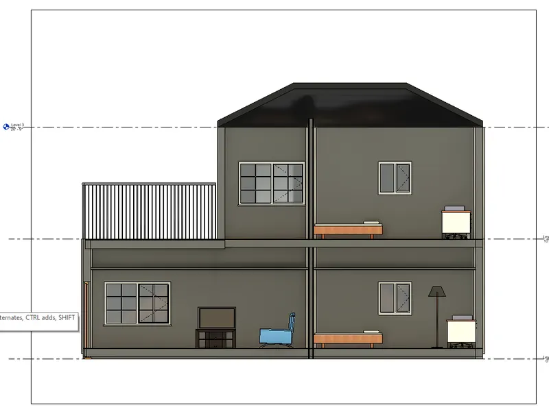
AIM: To provide section cut in living area,kichten,bed room,toilet.
INTRODUCTION:
- A section is a cross section in a building model that you place by drawing a line.he view associated with this section is known as a section view.
- There are three default types of sections: building, wall and detail.
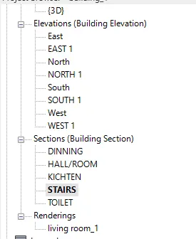
- Each type of section appears in a separate listing in the Project Browser.
- You can split sections into segments that are at right angles to the view direction.
- You can then use these segments to show parts of a building model located at different distances.
PROCEDURE:
- Go to view toolbar and select section.
- cut the building in longitudinall way crossing bedroom and hall.
- drag the dash line to show the area to be visible in the cut.
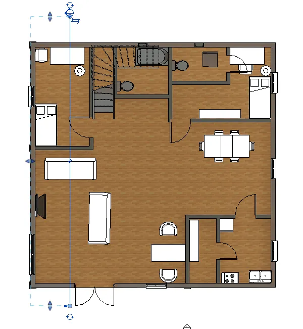
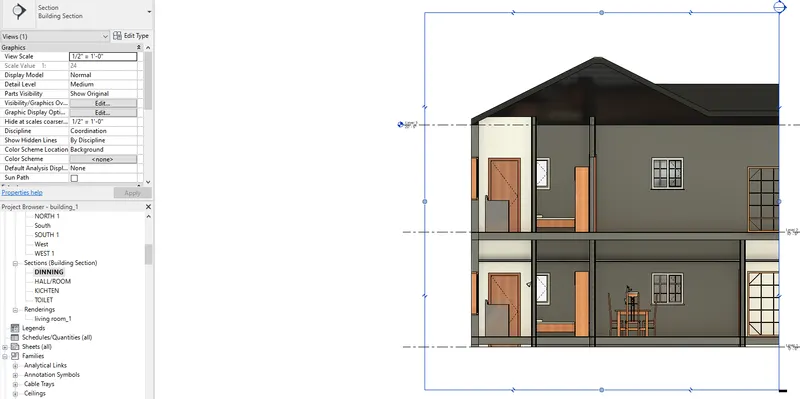
- auotmatically the section view will be saved in project browser.
- repeat the same for remaining rooms also.
RESULT:
8) Classify the views, Plan Views, Section Views, and Elevation views to either Design or Documentation category using Properties browser
AIM: To classify view,plan views,section views and elevation and document views using properties browser.
INTRODUCTION: Property browser shows a logical hierarchy for all views, schedules, sheets, groups, and other parts of the current project. As you expand and collapse each branch, lower-level items display.
PROCEDURE:
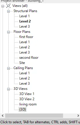
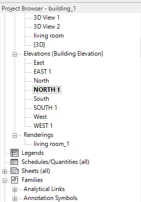
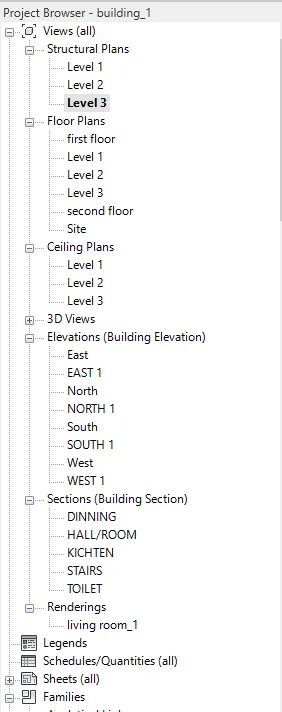
- when views are created using 3d view/plan view/elevation view,it automatically get saved in the project browser.
- project browser display the viws as show below.
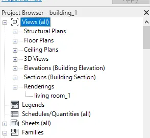
- click on floor plan to get expand and its display views and drafted levels together.
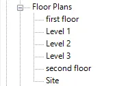
- click on particular view to display on the screen.
- simialry in structural plan holds the structural views.
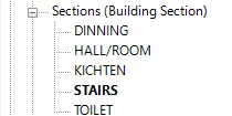
- section plan holds all sectional views created by us.
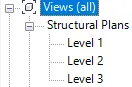
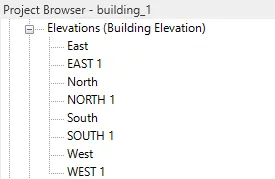
- similalry elevation plan holds normal north,south,east and west including any additional elevation views created by us.
RESULT:
9) Using the sheet template produced create multiple sheets as follows
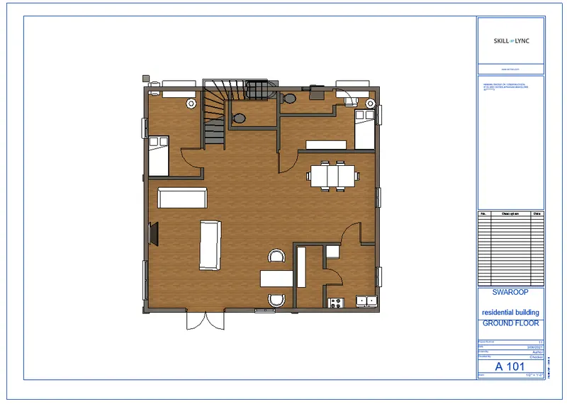
a. A 101- Ground Floor Architecture Plan
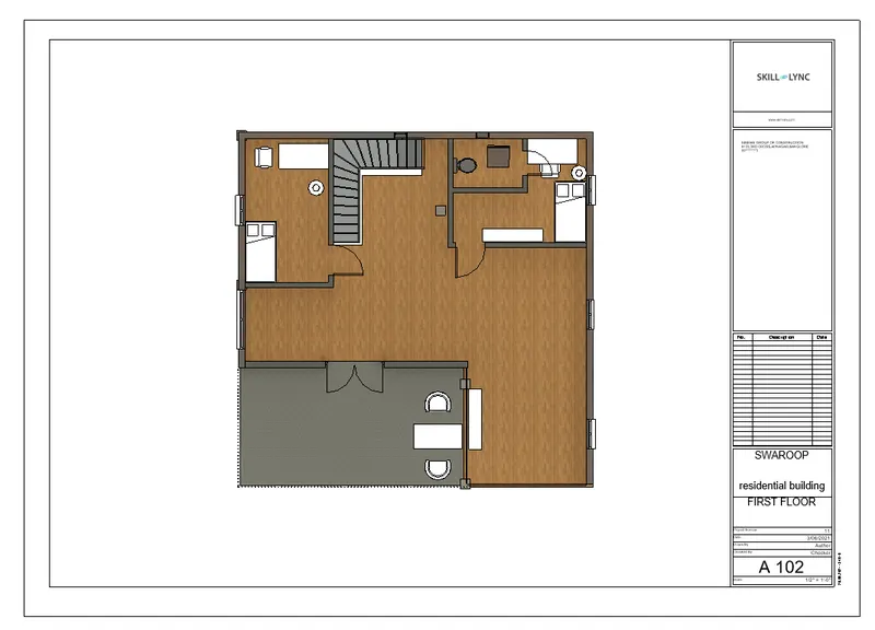
b. A 102- First Floor Architecture Plan
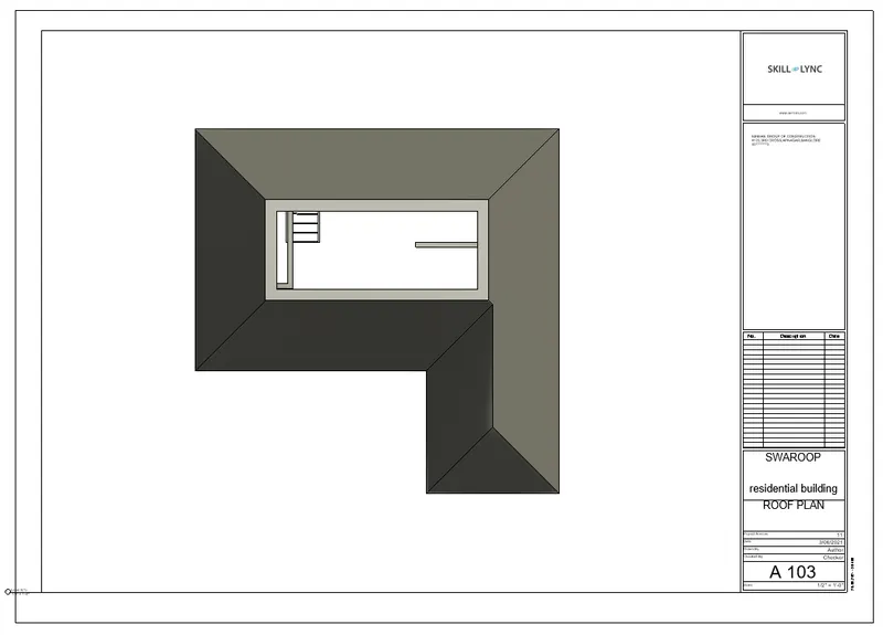
c. A 103- Roof Plan
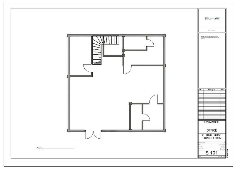
d. S 101- Ground Floor Structural Plan
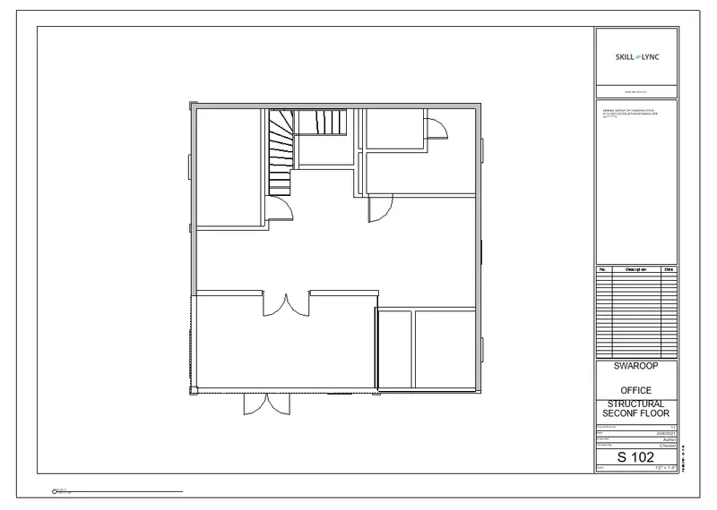
e. S 102- First Floor Structural Plan
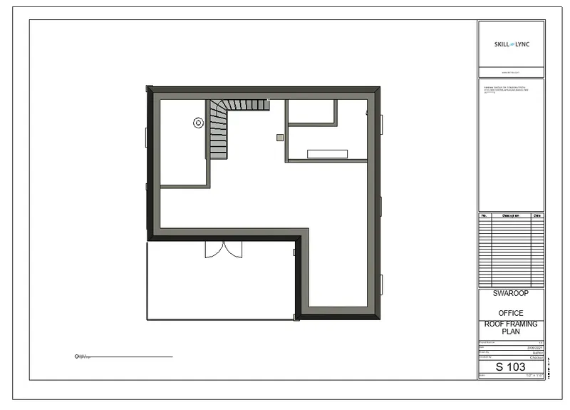
f. S 103- Roof Framing Plan
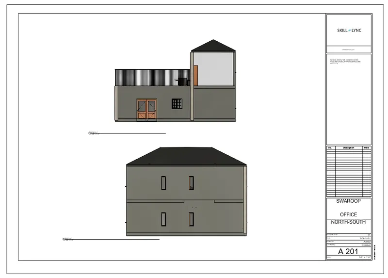
g. A-201- North-South Elevations
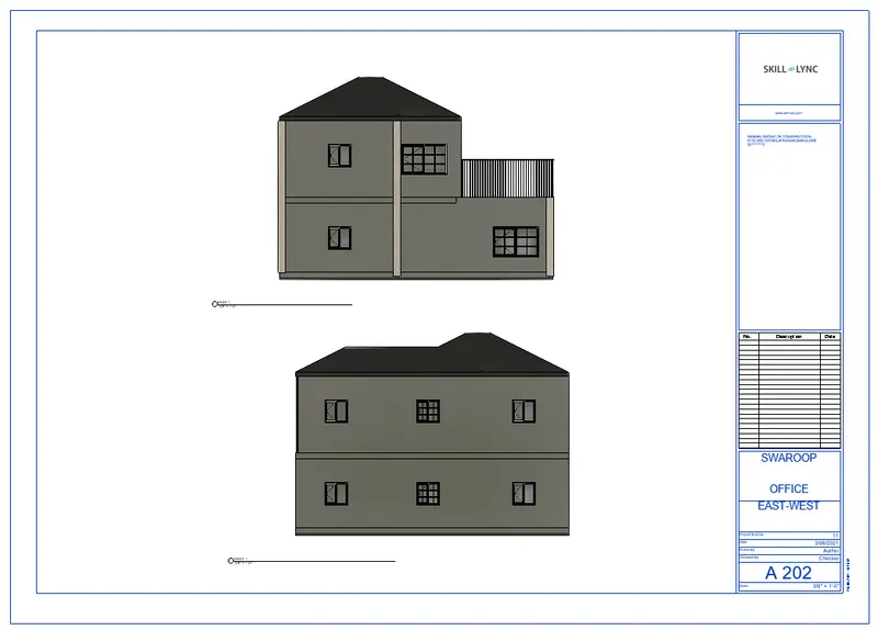
h. A-202- East-West Elevations
Add additional sheets based on the sections created in your Revit file
AIM: To create sheet template for architecural plan,strcutural plan,sectional plan,roof plan,elevation plan.
INTRODUCTION:
- In Revit you create a sheet view for each sheet in the construction document set. You can then place multiple drawings or schedules on each sheet view.
- Create views on a project template before you start building the model to streamline the project documentation process.
PROCEDURE:
- Go to view toolbar,select sheets.
- edit the sheet and name the sheet number as A 101.
- go to view toolbar and select view,select architecture groundfloor plan.
- place it in the template and adjust using scale tool.
- simialry A 102 for first floor architecture.
- repeat the same procedure for rmenaing plan sheets with different sheet number.
RESULT:
a. A 101- Ground Floor Architecture Plan
b. A 102- First Floor Architecture Plan
c. A 103- Roof Plan
d. S 101- Ground Floor Structural Plan
e. S 102- First Floor Structural Plan
f. S 103- Roof Framing Plan
g. A-201- North-South Elevations
h. A-202- East-West Elevations
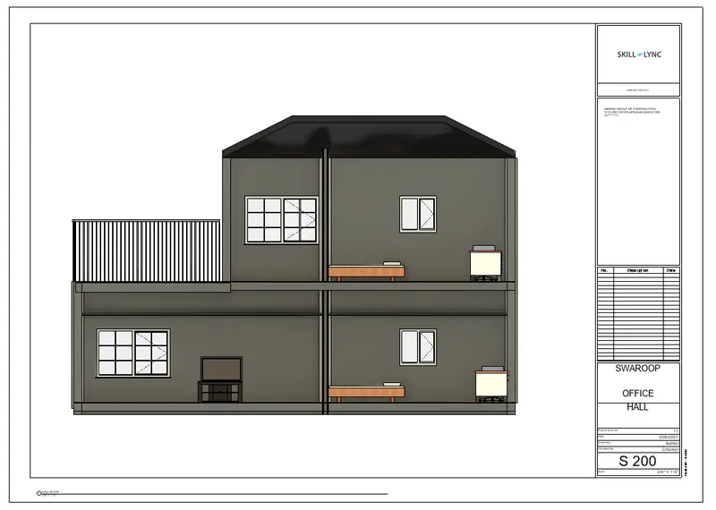
G- S 200- LIVING SECTION
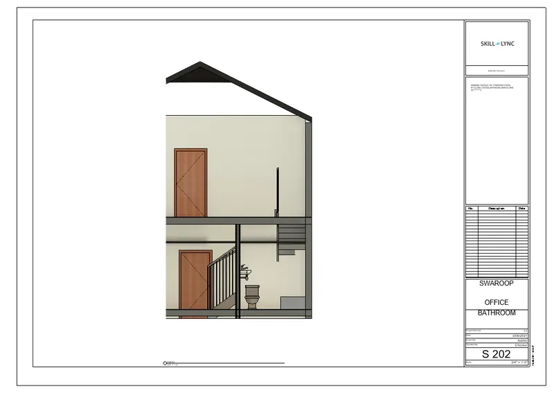
H-S 202-BATHROOM SECTION
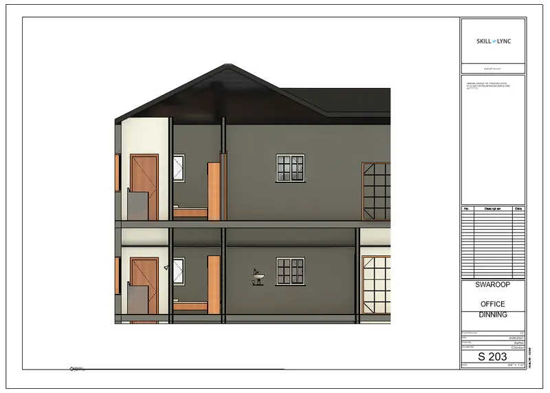
I-S 203-DINNING SECTION
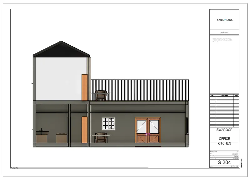
J-S 204-KICHTEN SECTION
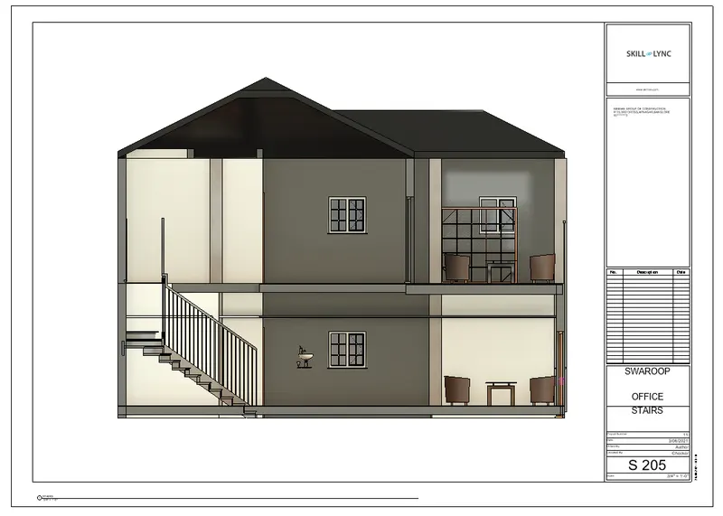
K-S 205-STAIRS SECTION
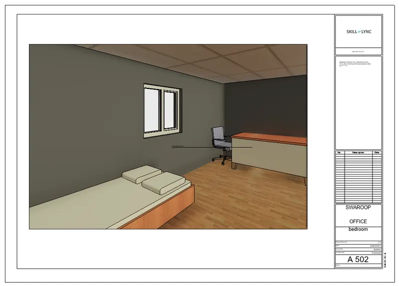
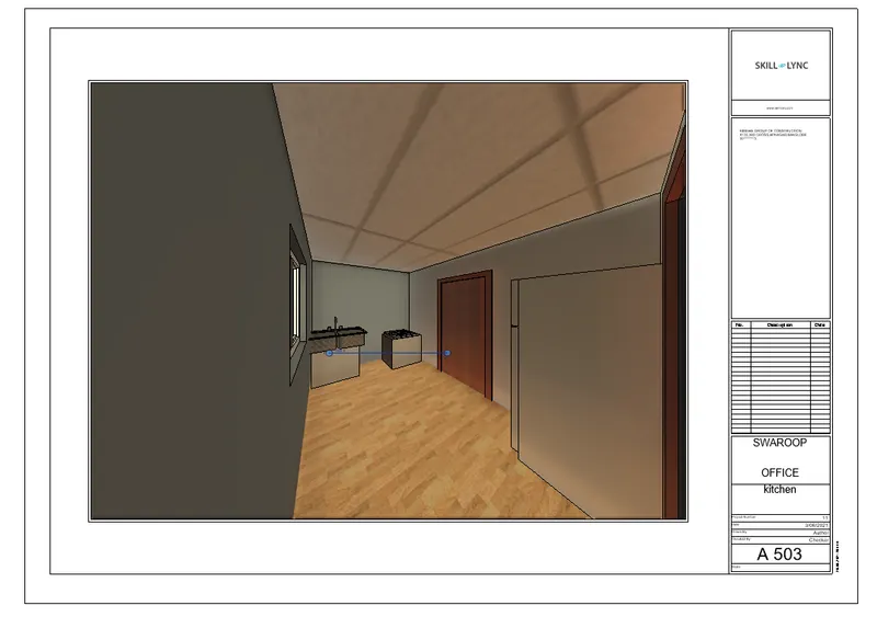
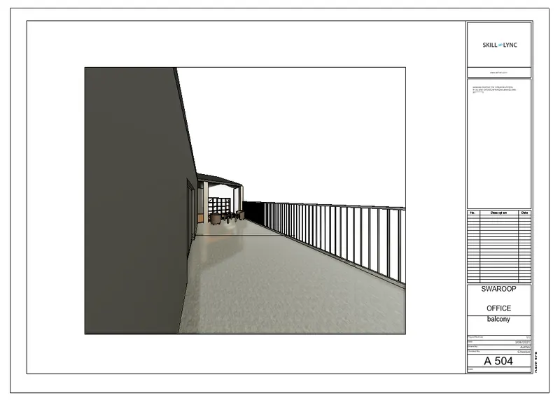
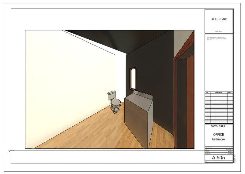
10) Create a camera-specific view or a 3D view in each room ( living, dining, bedroom). Based on the views create a new set of sheets starting A-501 (you can add as many sheets after, 502, 503.. n)to place the 3D view images. Produce the sheets as a part of project drafting.
AIM: To create a redenring of living,dinning,bathroom.
INTRODUCTION:
- camera view helps to seethrough things inside the building.
- this give breif idea how building appears before construction.
PROCEDURE:
- go to view and select camera under 3d view.
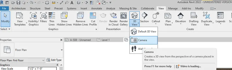
- place the camera in BED room and set the angle which display maximum things in room.
- the view will be saved under 3d view and acn be renamed later.
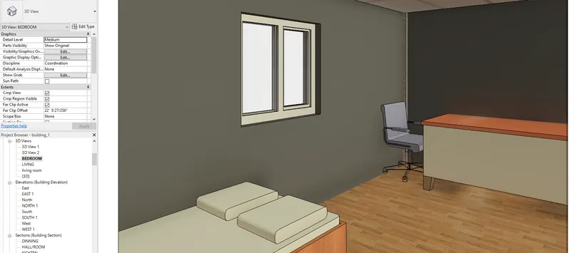
- simialry repeat the same for remaining area.
- now select the sheet and edit the titleblock family.
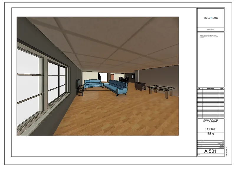
- place the living camera view in sheet named A-501.
- adjust the view help of scale.
- simialry repeat the same for remaining camera view under different sheet number.
RESULT:
A 501-LIVING
A 502-BEDROOM
A 503-KITCHEN
A 504-BALCONY
A 506-DRAWING AREA