3D Creation of Celing, Roof, Architectural plan, Structural plan, Sectional view, Elevation view and Camera specific view for a house plan using REVIT
Challange : 4
3D Creation of Celing, Roof, Architectural plan, Structural plan, Sectional view, Elevation view and Camera specific view for a house plan using REVIT
Question : 1>
Based on the project saved from Week 3, proceed from the First Floor Level. Model a Ceiling from the architecture tab above the walls at the first-floor level
Aim: To Model a Ceiling above the walls at the first-floor level in Revit.
Tools Used: architecture tab, Ceiling.
Procedure:
- Open a ceiling plan view.
- Click Architecture tab Build panel (Ceiling).
- In the Type Selector, select a ceiling type.
- Place a ceiling using one of the following methods: Use walls as ceiling boundaries. By default, the Automatic Ceiling tool is active.
- By default, the Automatic Ceiling tool is active.
- When you click inside walls that form a closed loop, the tool places a ceiling within those boundaries. It ignores room separator lines.
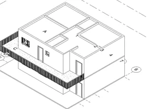
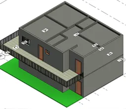
Result: The Ceiling is placed on the first floor walls as shown above.
Question : 2>
Model a roof above the ceiling by selecting the footprints of the ceiling. Using the adjustment toolbars appearing on-screen adjust the roof slope to 10 degrees
Aim: To Create a a roof above the ceiling at the first-floor level in Revit.
Tools Used: architecture tab, Roof,footprints .
Procedure:
- Display a floor plan view or a reflected ceiling plan view.
- Click Architecture tab Build panel Roof drop-down (Roof by Footprint). ...
- On the Draw panel, select a sketch or pick tool. ...
- Sketch, or pick, a closed loop for the roof.
- Specify slope defining lines.
- By default, the Automatic Ceiling tool is active.
- When you click inside walls that form a closed loop, the tool places a ceiling within those boundaries.
- It ignores room separator lines.
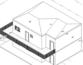
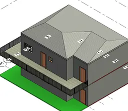
Result: The Roof is Created by using footprint above ceiling on the first floor walls as shown above.
Question : 3>
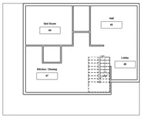
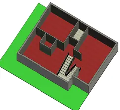
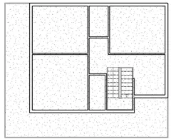
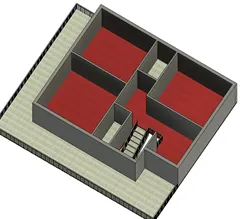
Using the file saved from weeks 2 to 4, create plan views for ground floor level and first-floor level including all the walls, floors, and components. Separate them to
architecture and structural plans
a. Architecture plan must have walls, floors, and all the components placed within the building
b. Structure plan must have details of only walls, floors, and columns
Aim: create plan views for ground floor level and first-floor level including all the walls, floors, and components.
Tools Used: View tab, view.
Procedure:
- The plan is already drawn in the project 3 any how we need to seperate the drawings,
- in the archetectural drawing all the components are shown,
- Like Furniture, Lightings, plumbing fixtures etc,
- And Windows and doors also visible.
- Hence take a look and add the components and take a screen shot and attach the images.
- Hence all the images are attached as shown below the procedure.
- In the Structural drawing all the components are shown,
- Like Walls, columns, etc,
- And Windows and doors can also be visible.
- Hence all the images are attached as shown below the procedure.
a. Architecture plan must have walls, floors, and all the components placed within the building
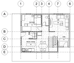
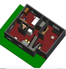
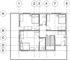
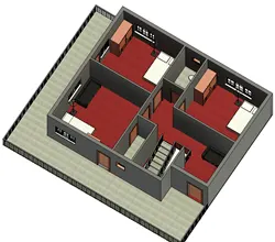
b. Structure plan must have details of only walls, floors, and columns
Question : 4>
Using annotate toolbar add dimensions to all the walls and floors with reference to the longitudinal and transverse grids created in the project file
a. The architecture plan dimensions include details on where the components are placed within the buildings with relation to grids. Overall dimensions are sufficient for architecture plans
b. The Structure plan dimensions must include details on the position of all the walls and interior walls with reference to grids. Locate all the framing components of the building with reference to a fixed point using Structural plans
Aim: To add dimensions to all the walls and floors with reference to the longitudinal and transverse grids.
Tools Used: Annotate, Alined.
Procedure:
- Click Annotate tab Dimensions panel Linear. Find.
- Specify the first and second extension line origin.
- At the prompt, enter r (Rotated).
- Enter an angle for the dimension line.
- Click to place the dimension line.
- Hence take a look and add the components and take a screen shot and attach the images.
- Hence all the images are attached as shown below the procedure.

- Click to place the dimension line.
- Hence take a look and add the components and take a screen shot and attach the images.
- Hence all the images are attached as shown below the procedure.
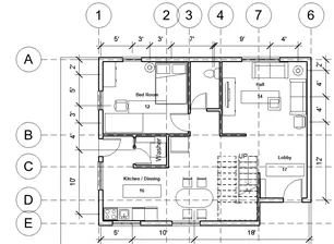
a. The architecture plan dimensions include details on where the components are placed within the buildings with relation to grids. Overall dimensions are sufficient for architecture plans
b. The Structure plan dimensions must include details on the position of all the walls and interior walls with reference to grids. Locate all the framing components of the building with reference to a fixed point using Structural plans
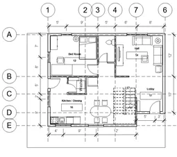
Result: The Dimensions have been placed with proper style with respect to grids both as architecture and Structural Formate As Shown in the Fig.
Question : 5>
Create a sheet template from the view tab and adjust the parameters on the sheet to add appropriate views
Aim: Create a sheet template and adjust the parameters on the sheet to add appropriate views.
Tools Used: View tab, view.
Procedure:
- To add project templates to the Project Templates list
- Create the project templates that you want to include in the list.
- Click File tab
- Click the File Locations tab.
- Add one or more templates to the Project template files list, as follows:
- Click (Add Value).

- Click the File Locations tab.
- Add one or more templates to the Project template files list, as follows:
- Click (Add Value).
- Navigate to the project template file, select it, and click Open.
- The template is added to the list.
- The default location for project template files is: USERSPROFILE\Autodesk\RVT 2018\Templates\
- Under Name, replace the default template name with a meaningful name.
- Note:To change the template, click in the Path column, and select
- Rearrange the list to put templates in the desired order. Select a template row and use (Move Rows Up) and (Move Rows Down) to move templates to the desired position.
- The first 5 templates listed in the table will appear on the Recent Files window under Projects,
- providing quick access. When creating a project, the full list of project templates is available on the New Project dialog.
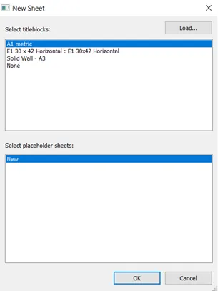
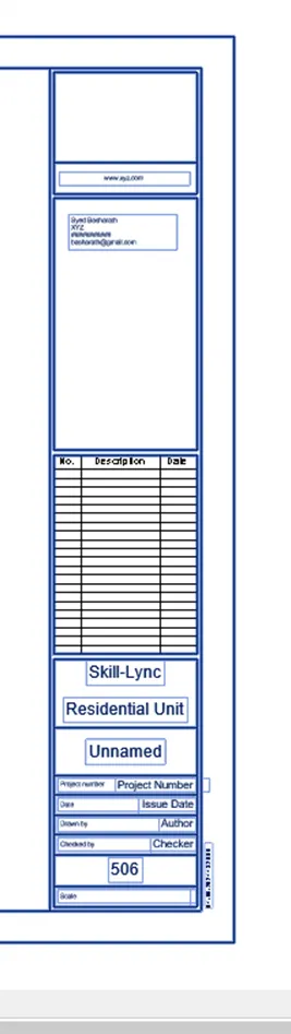
Result: The sheet template is created and adjust the parameters on the sheet as Shown in the above fig.
Question : 6>
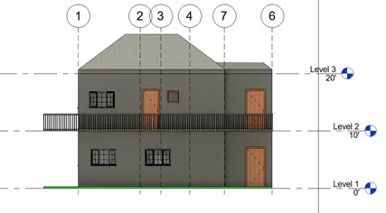
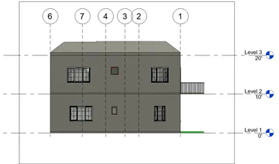
Using the elevation tab create the elevation views, looking at your building from East, North, South, and West
Aim: create the elevation views, looking at your building from East, North, South, and West.
Tools Used: View tab, Elevation.
Procedure:
- Open a plan view.
- Click View tab - Create -panel Elevation drop-down(Elevation).
- The cursor appears with the elevation symbol.
- Optional) In the Type Selector, select a view type from the list, or click Edit Type to modify an existing view type or create a new view type.
- Place the cursor near a wall, and click to place the elevation symbol.
- Note:As you move the cursor, you can press Tab to change the position of the arrowhead. The arrowhead snaps to perpendicular walls.
- To set different interior elevation views, highlight the square shape of the elevation symbol, and click.
- The elevation symbol displays with check box options for creating views, as the following image shows.
- Tip:The rotation control is useful for aligning to angled elements in the plan.
- Select the check boxes to indicate where you want to create elevation views.
- Click away from the elevation symbol to hide the check boxes.
- Highlight an arrowhead on the symbol to select it.
- Click the arrowhead once to view the clip plane:
- Elevation symbol with clip plane
- The end points of clip planes snap and join to walls. You can resize the width of the elevation by dragging the blue controls.
- If the blue controls do not display in the view, select the clip plane and click Modify Views tab Element panel Element Properties.
- In the Instance Properties dialog, select the Crop View parameter, and click OK.
- In the Project Browser, select the new elevation view.
- The elevation view is designated by a letter and number, for example, Elevation: 1 - a.
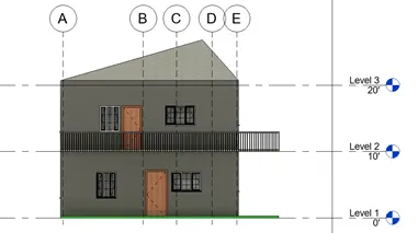
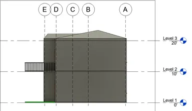
Result: Using the elevation tab the elevation views, from East, North, South, and West is Created and as shown in above figure.
Question : 7>
Produce section cut through each room either cutting across longitudinally or in a transverse direction
Aim: create the section cut through each room either cutting across longitudinally or in a transverse direction.
Tools Used: View tab, Section.
Procedure:
- Open a plan, section, elevation, or detail view.
- Click View tab Create panel(Section).
- (Optional) In the Type Selector, select a view type from the list, or click Edit Type to modify an existing view type or create a new view type.

- Place the cursor at the starting point of the section, and drag through the model or family.
- Note:You can snap a section line parallel or perpendicular to a non-orthogonal datum or wall. Snapping to a wall is available in plan views.
- Click when you reach the end point of the section.
- The section line and the crop region appear and are selected.
- If desired, resize the crop region by dragging the blue controls. The depth of the section view changes accordingly.
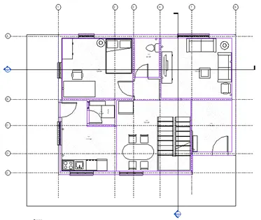
- Click Modify or press Escto exit the Section tool.
- To open the section view, double-click the section header, or select the section view from the Sections grouping of the Project Browser.
- The section view changes when the design changes or the section line is moved.
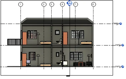
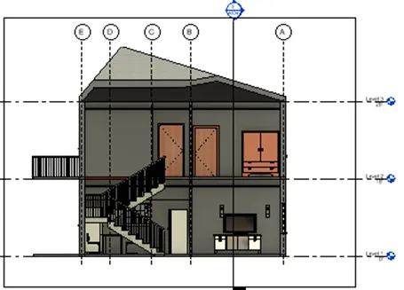
Result: The section cut through across longitudinally and in a transverse direction as shown in fig.
Question : 8>
Classify the views, Plan Views, Section Views, and Elevation views to either Design or Documentation category using Properties browser
Aim: create the views, Plan Views, Section Views, and Elevation views to either Design.
Tools Used: Properties, Section.
Procedure:
- Open a plan view.
- Click View tab - Create -panel Elevation drop-down(Elevation).
- The cursor appears with the elevation symbol.
- Optional) In the Type Selector, select a view type from the list, or click Edit Type to modify an existing view type or create a new view type.
- Place the cursor near a wall, and click to place the elevation symbol.
- Note:As you move the cursor, you can press Tab to change the position of the arrowhead. The arrowhead snaps to perpendicular walls.
- To set different interior elevation views, highlight the square shape of the elevation symbol, and click.
- The elevation symbol displays with check box options for creating views, as the following image shows.
- Tip:The rotation control is useful for aligning to angled elements in the plan.
- Select the check boxes to indicate where you want to create elevation views.
- Click away from the elevation symbol to hide the check boxes.
- Highlight an arrowhead on the symbol to select it.
- Click the arrowhead once to view the clip plane:
- Elevation symbol with clip plane
- The end points of clip planes snap and join to walls. You can resize the width of the elevation by dragging the blue controls.
- If the blue controls do not display in the view, select the clip plane and click Modify Views tab Element panel Element Properties.
- In the Instance Properties dialog, select the Crop View parameter, and click OK.
- In the Project Browser, select the new elevation view.
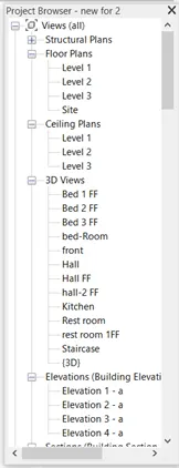
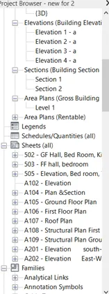
Result: The views, Plan Views, Section Views, and Elevation views to either Design Properties browser is Created as shown.
Question : 9>
9) Using the sheet template produced create multiple sheets as follows
a. A 101- Ground Floor Architecture Plan
b. A 102- First Floor Architecture Plan
c. A 103- Roof Plan
d. S 101- Ground Floor Structural Plan
e. S 102- First Floor Structural Plan
f. S 103- Roof Framing Plan
g. A-201- North-South Elevations
h. A-202- East-West Elevations
Add additional sheets based on the sections created in your Revit file
Aim: create the the sheet template produced create multiple sheets.
Tools Used: View, Sheet Selection, view sheet.
Procedure:
- To add project templates to the Project Templates list
- Create the project templates that you want to include in the list.
- Click File tab
- Click the File Locations tab.
- Add one or more templates to the Project template files list, as follows:
- Click (Add Value).
- Click the File Locations tab.
- Add one or more templates to the Project template files list, as follows:
- Click (Add Value).
- Navigate to the project template file, select it, and click Open.
- The template is added to the list.
- The default location for project template files is: USERSPROFILE\Autodesk\RVT 2018\Templates\
- Under Name, replace the default template name with a meaningful name.
- Note:To change the template, click in the Path column, and select
- Rearrange the list to put templates in the desired order. Select a template row and use (Move Rows Up) and (Move Rows Down) to move templates to the desired position.
- The first 5 templates listed in the table will appear on the Recent Files window under Projects,
- providing quick access. When creating a project, the full list of project templates is available on the New Project dialog.
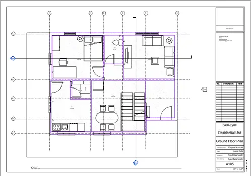
a. A 101- Ground Floor Architecture Plan
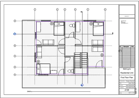
b. A 102- First Floor Architecture Plan
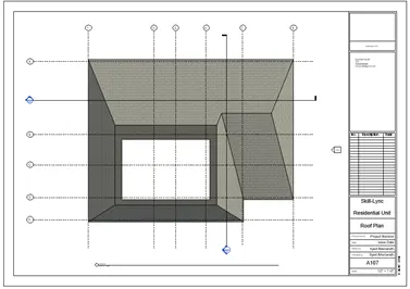
c. A 103- Roof Plan
d. S 101- Ground Floor Structural Plan
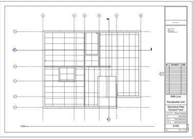
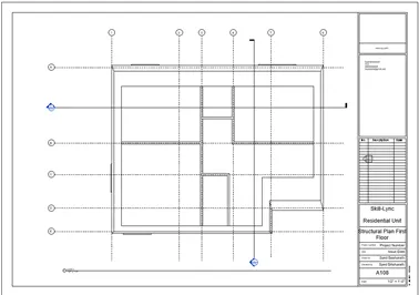
e. S 102- First Floor Structural Plan
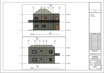
g. A-201- North-South Elevations
h. A-202- East-West Elevations
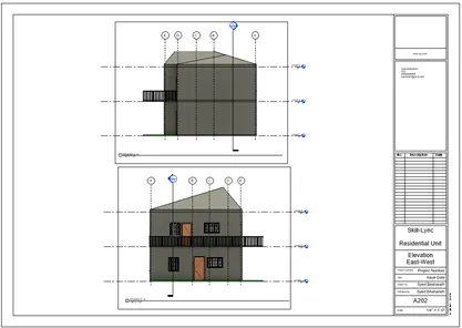
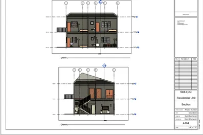
Result: The views, Plan Views, Section Views, and Elevation views is placed in the template and edited the templete respectively as shown in the figure.
Question : 10>
Create a camera-specific view or a 3D view in each room ( living, dining, bedroom). Based on the views create a new set of sheets starting A-501 (you can add as many sheets after, 502, 503.. n)to place the 3D view images. Produce the sheets as a part of project drafting.
Aim: Create a camera-specific view or a 3D view in each room ( living, dining, bedroom). Based on the views create a new set of sheets.
Tools Used: View, Sheet Selection, view sheet.
Procedure:
- After creating your 3D model in Revit, of course, you want to show off your model.
- In this post, we will discuss placing and fine-tuning our camera. And we will also discuss how to create a 3D section by controlling the section box.
- Placing of Camera, you can place a camera by activating it from your ribbon, View tab, Create panel.
- Click the small arrow near the 3D view, and click the camera button on the drop-down menu.
- Then you can define the camera by two clicks: the camera position and target position.
- After you define the camera, Revit will automatically open a new view. This view will show you what your camera sees. Mostly we need to modify the view.
- Make sure modify is active, click the view boundary. You will see the blue grips on the rectangle sides. You can resize the boundary by dragging the grip.
- You can fine-tune moving your camera around by holding [shift] + mid button.
- Bird Eye View, that’s how we can place the camera. Pretty easy, I guess.
- But sometimes we want to get the ‘wow effect’ by placing the camera at a high or low angle. Try to place another camera,
- but before you define the position, look at the options bar. We can define the camera height.
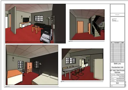
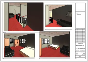
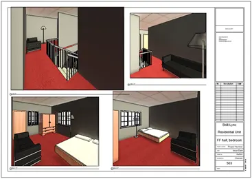
Result: Views obtained by placing camera in each rooms is placed in the template and edited the templete respectively as shown in the figure.