3D Creation of Celing, Roof, Architectural plan, Structural plan, Sectional view, Elevation view and Camera specific view for a house plan using REVIT
Question 1) Based on the saved project from week 3, continue from the first floor. Model the Ceiling from the Architecture tab above the walls at the first floor level
Reply:
aim: Model the ceiling from the Architecture tab above the walls at the first floor level.
Introduction:
The ceiling is the upper internal surface that covers the upper boundaries of the room. It is generally not considered a structural element, but a finished surface covering the underside of a roof structure or a floor above a floor.
Creating ceilings in Revit is a very similar process to Floors and Roofs - ie you can let Revit do most of the work and "step over" where you want the boundaries. Or you can enter sketch mode and literally sketch the ceiling border yourself.
The main thing to remember is to be in the Connect Ceiling Plan View before you start. Revit allows you to place ceilings in the floor plan
In this Revit Architecture tutorial, I will show you how to create ceiling elements both "automatically" and using the "sketch method".
TYPES OF DRAWINGS:
Automatic creation of ceilings
Creating ceilings using a sketch
Alignment of suspended ceiling grids
Like floors and roofs, Revit ceilings consist of 3D model geometry and non-graphical parametric data. They are created using a special Strop tool. There are 2 ways to create ceilings - each has its advantages and disadvantages, which I will explain at the end of the tutorial. To make this tutorial a little more realistic, I've created a simple building that we can add some ceiling elements to
Method:
STEP 1: Start the 3rd week project
Open Revit Software
From recent projects Open 'My Home Architectural'
STEP 2:
First, we open the revit software and select the ceiling option from the architecture toolbar.
STEP 3: Creating the ceiling
In the project, click in the browser to open the first floor plan
Go to the Architecture tab
Click Ceiling to model the ceiling for the first floor
Select type as 2'X4' ACT System
Select the desired ceiling area as shown below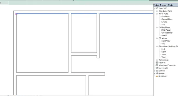
the ceiling is created in the required area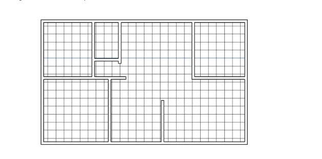
Result:
The height offset of the ceiling varies depending on the characteristics of the ceiling. The result after placing the ceiling over the first floor is shown below.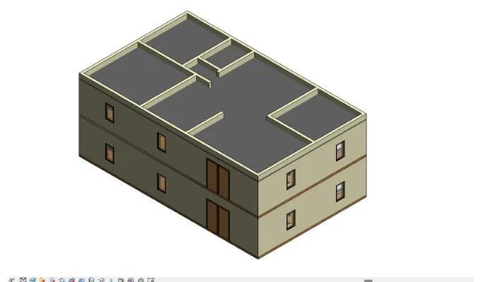
Question 2) Model the roof above the ceiling by selecting the ceiling tracks. Adjust the pitch of the roof to 10 degrees using the adjustment toolbars that appear on the screen
Reply:
aim: Model the roof to the ceiling on the first floor
Introduction:
A roof is the top covering of a building, including all materials and structures necessary to support it on the building walls or uprights, protecting against rain, snow, sunlight, extreme temperatures and wind. The roof is part of the building envelope.
Roof, covering the top of a building, used to protect against rain, snow, sunlight, wind and extreme temperatures
The roofs were constructed in a wide variety of forms flat, pitched, arched, vaulted or in combinations according to technical requirements. economic or aesthetic considerations The earliest roofs built by man were probably thatched roofs, which were made of straw.
leaves, branches or reeds; they were usually set on a slope so that rain could run off them.
Conical thatched roofs are a good example of this type and are still widely used in rural areas of Africa and elsewhere
Thicker branches and beams eventually came to be used to span the roof, with clay or some other relatively impermeable material pressed into the gaps between them.
Gable and flat roofs were possible with these materials. With the invention of bricks and cut stone for construction, the basic roof form of the dome and vault appeared.
Method:
STEP 1: Start the 3rd week project
Open Revit Software
From recent projects Open 'My Home Architectural'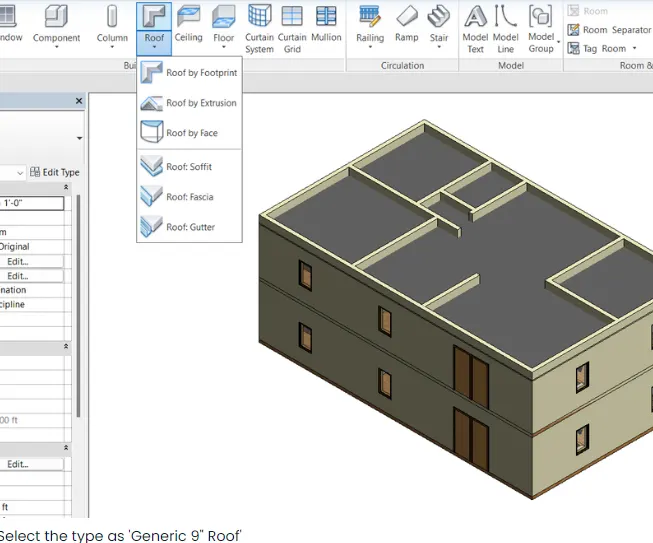
STEP 2: Creating a roof over the first floor
Open the first floor plan in the project browser
In the project browser, click to open the first floor plan
Go to the Architecture tab
Click the Roof tab to model the roof for the first floor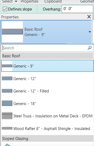
Select type as 'Generic 9" Roof'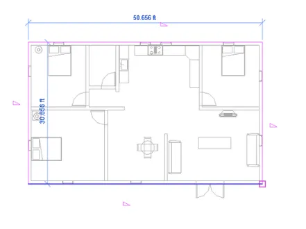
Select the desired roof area as shown below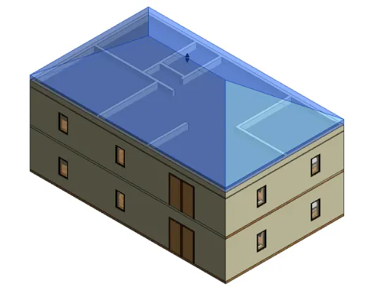
I changed the color of the walls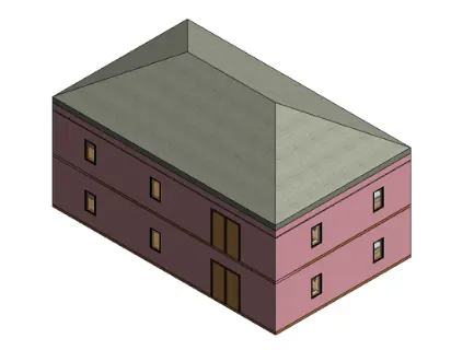
Result:
The base level is set to Roof Level. The roof after creation is as follows.
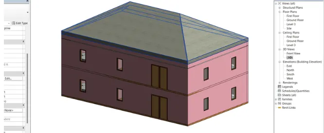
3) Using the file saved from weeks 2 to 4, create floor plan views for the ground floor level and first floor level including all walls, floors and components. Separate them from architecture and building plans
Reply:
aim: Using the file saved from Weeks 2-4, create plan views for the ground floor and first floor levels including all walls, floors and components. Separate them from architecture and building plans
Introduction:
The structural floor plan view is the default view when you start a new project using a structural template. Most projects contain at least one structural plan. New construction floor plans are created automatically when you add new levels to the project. You can create multiple types of structural plan views
The plan view is the default view in a new architectural project. - Most projects contain at least one floor plan.
Plan views are created automatically when new levels are added to the project.
Method:
STEP 1: Open the project
Open Revit Software
From recent projects Open 'My Home Architectural'
STEP-2: Creating an architectural plan
Go to the Properties browser and open floor plans as needed
Click on Ground Floor Plan to open the Ground Floor Plan 2D layout
The architectural plan of the ground floor consists of walls, stairs, windows, doors
Parts of the kitchen, living room, bedroom, toilet, pantry.
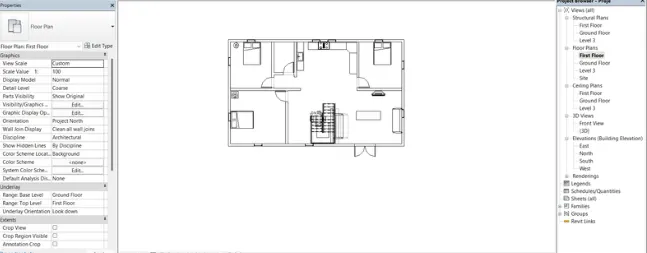
The floor plan of the ground floor is shown below
A. The architecture plan must have walls, floors and all components located in the building
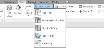
Open a new sheet and set the unit
set levels
Select the view option from the toolbar above
And took plan views on the right side
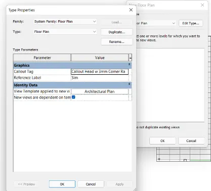
They have some option in the floor plan views, just choose the floor plan
And click edit option, set architecture
And click OK to show the architecture plan on the screen
b. The structure plan must include details of walls, floors and columns only:
Same as above option
Open a new sheet and set the unit
set levels
Select the view option from the toolbar above
And took plan views on the right side
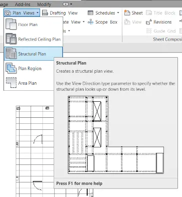
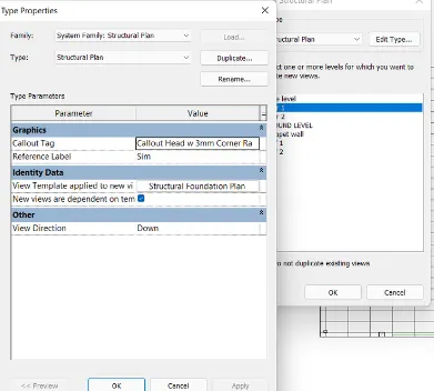
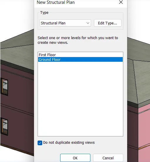
They have some option in the floor plan views, just choose the construction plan
It can automatically display the structural view in the plan
Construction plan of the ground floor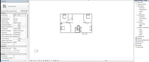
Result:
Architectural and construction plan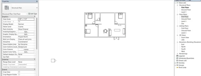
4) Use the annotation toolbar to add dimensions to all walls and floors, referencing the longitudinal and transverse meshes created in the project file
A. Architecture plan dimensions include details of where components are located in buildings in relation to grids. The overall dimensions are sufficient for architectural plans
b. The floor plan dimensions of the structure must include details of the location of all walls and interior walls with reference to grids. Use structural plans to locate all building framing elements with reference to a fixed point
Reply:
aim: Use the Annotation Toolbar to add dimensions to all walls and floors, referencing the longitudinal and transverse meshes created in the project file
Introduction:
A structural floor plan is the default view when you start a new project using a structural template.
Most projects contain at least one structural plan. New construction floor plans are created automatically when you add new levels to the project. You can create multiple types of structural plan views.
The plan view is the default view in a new architectural project. Most projects contain at least one floor plan.
Plan views are created automatically when new levels are added to the project.
Method:
STEP-1: Creating the grid
Go to the Architecture tab
Click GRIDS in the right corner
Draw grids as shown below
The horizontal grids are named - A, B, C, D
The vertical grids are named - 1, 2, 3, 4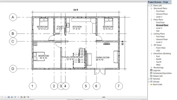
STEP-2: Architectural notes
Notes are created for components related to the grid line created as shown below.
The following image shows the notes for doors and windows in NE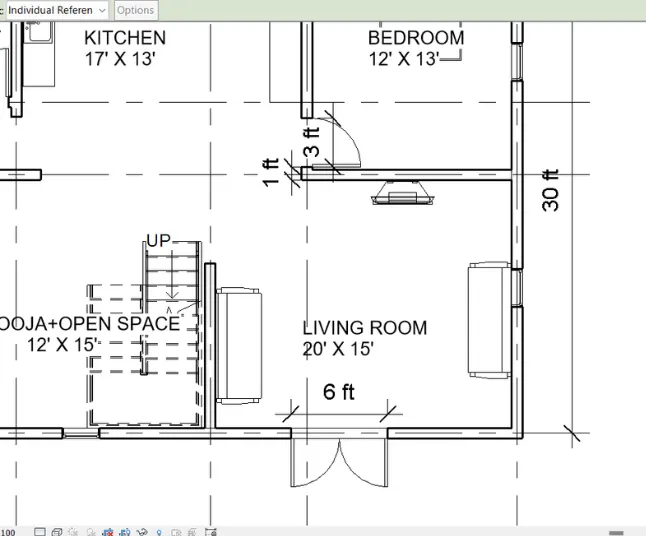
STEP 3: Structural notes
For the center lines of the wall, notes are made regarding the grid created as shown below.
In the wall descriptions below, the axes are shown below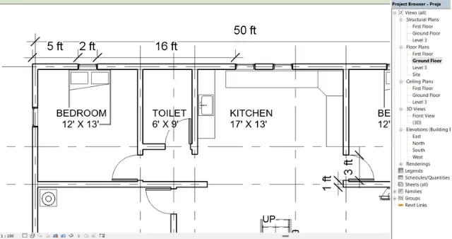
Result:
The images below show the architectural and structural annotations of the given project
1. Architectural Notes: Show distance for residential building architectural features with respect to grid lines
2. Construction Notes: Show the distance for the residential building structural elements relative to the grid lines
5) On the view tab, create a sheet template and edit the parameters on the sheet to add the appropriate views
Reply:
aim: Create a sheet template and edit parameters
Introduction:
In Revit, you create a sheet view for each sheet in the design document set. You can then place multiple drawings or plans on each sheet view. In Revit, you create a sheet view for each sheet in the design document set. You can then place multiple drawings or plans on each sheet view. About Tables in project templates. Before you start building the model, create views on the project template to simplify the project documentation process.
A set of construction documents (also called a set of drawings or a set of sheets) consists of several sheets. Topics in this section. About Tables. In Revit, you create a sheet view for each sheet in the design document set.
You can then place multiple drawings or plans on each sheet view.
Add sheet:
Open the project.
Click the View tab Sheet Composition panel (Sheet).
Select a corner stamp as follows: In the New Sheet dialog, select a corner stamp from the list. ...
Enter the information in the header of the sheet.
Add views to the sheet.
Change the default number and name that Revit assigned to the sheet.
Method:
STEP 1: Open the project and layout the sheet
Open the "My Home Architectural" project
Go to the Insert tab
Click Load Family
Click on the header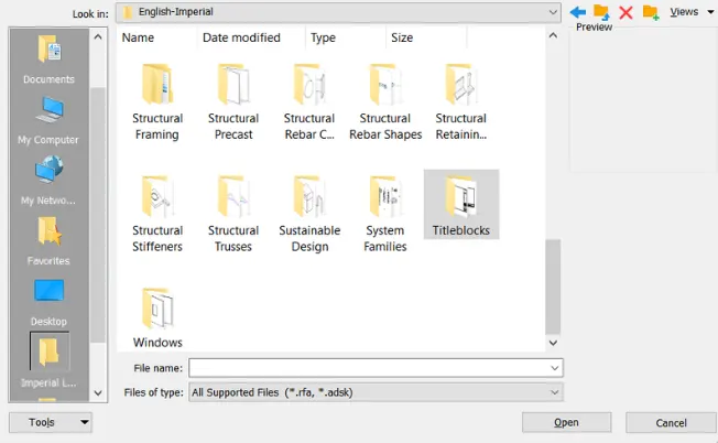
Select any template as needed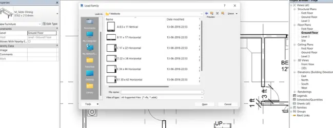
Go to the project browser and right-click on the sheet
Click Add New Sheet
Select the D22X34 Horizontal template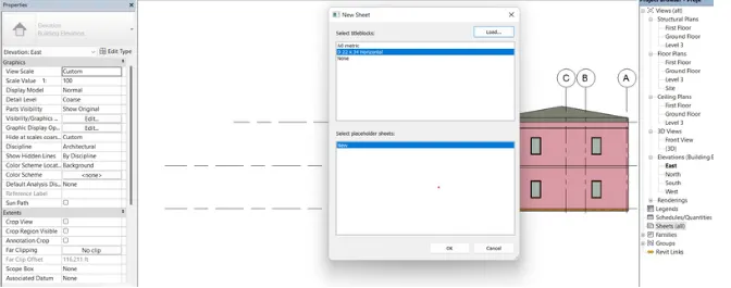
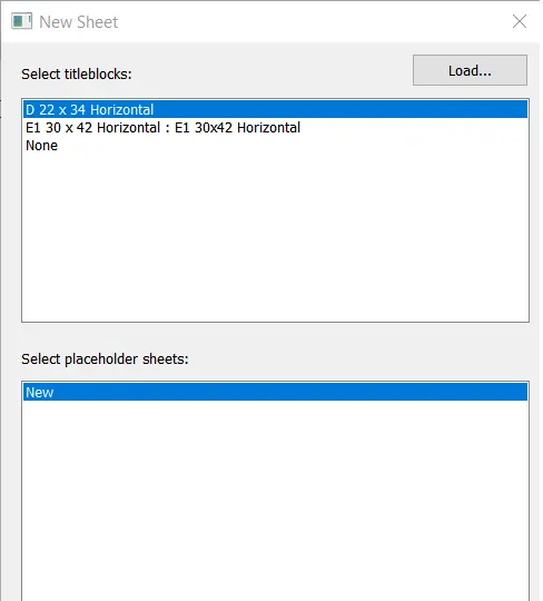
click ok
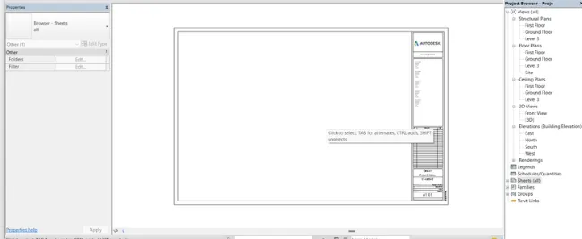
STEP-2: Changing parameters
Parameters such as project name. Involved consultants are changed/edited according to our project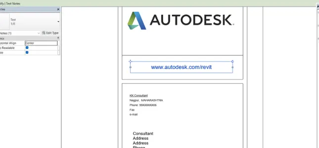
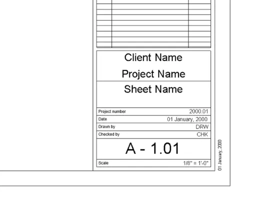
Result:
The corner stamp after changing / adjusting all parameters is as follows
Question 6) Use the Elevation tab to create views looking at the building from East, North, South and West
Reply:
aim: Create elevation views of the project
Introduction: Elevation is a side view of a structure. Aim explains that the view is not only a side view, but it is also a side view from the outside of the structure. This view can convey information that includes vertical dimensions, heights, door and window locations, and exterior finishes.
Method:
STEP 1: Creating views
Go to the View tab
Click on 'height'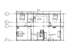
STEP 2: Create elevation points
Go to floor plan view in the project browser
Place the elevation marker point at the designated location/direction (ie east) as follows
STEP 3: Open the elevation view
Go to the project browser
Click the + next to "elevation" to view the full elevation view, and click a single view to open it
Result: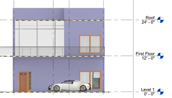
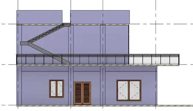
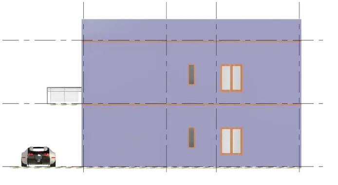
question 7)
aim: Create a cut by cutting
Introduction:
The section view gives architects and contractors another way to understand how a structure will hold up, as it reveals details of wall construction and the thickness and height of beams and other supports. While the floor plan allows a view of the relative position of the walls, the section shows where the wall meets the floor and the distance that separates one floor from another.
Method:
Step 1: Create a cut line
Go to the View tab
Click on 'Sections'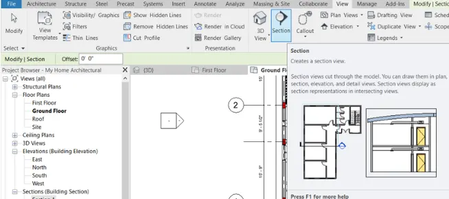
Step 2: Drawing the section line
Place the curse to one side of the cut line location
Draw a vertical line and click on the second point at the other end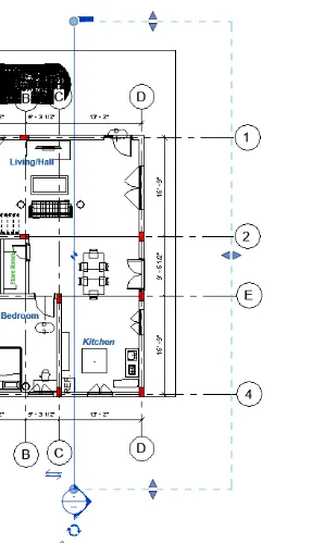
Result:
The resulting cut of the cut line created is as follows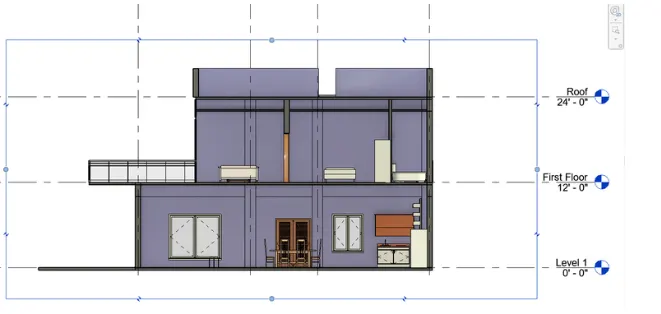
question 8)
aim: To classify different views
Introduction:
Using view types, you can quickly apply certain graphic properties and view templates to new views or change graphic properties for existing views. Do one of the following: Note: When you change the view type for an existing view, only the graphics properties are applied to the view.
Method:
1. Floor Plans: Floor plans are a 2D view of a residential building showing the components of the house with dimensions and labels
A. Ground floor plan
b. First floor plan
C. Roof plan
2. Ceiling Plans: Ceilings of different floors just below the roof
A. Ground floor plan
b. First floor plan
3. 3D- Views: 3D view of different rooms of the residential building
A. Living room
b. Master bedroom
C. Kitchen
d. Bathroom
E. Staircase
F. Storage room
G. 3D view of a residential building
4. Elevation: These views are useful in determining the height components of a residential building extract and the location of the components
A. Eastern
b. Northern
C. West
d. Southern
5. Sectional Views: Shows the internal configuration of components such as walls, architectural elements, etc.
A. Section 1
6. Sheets: Various sheets created for client presentations
A. A101-103
b. A201-203
C. 3D101-106
d. C101
Result:
The views classified above correspond to the project viewer below
question 9)
aim: Create multiple sheets for different views
Introduction:
In Revit, you create a sheet view for each sheet in the design document set. You can then place multiple drawings or plans on each sheet view. About Tables in project templates. Before you start building the model, create views on the project template to simplify the project documentation process.
Method:
Step 1: Open the sheet template
Go to the project browser
Click on Tables (all)
Right-click to add a new sheet or
Click + to open previously made sheets
Step 2: Add views to the template
Go to the project browser
Click on Tables (all)
Right-click to add a new sheet or
Click + to open previously made sheets
Right click on the sheet to add a sheet view as shown below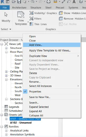
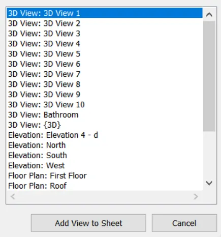
Select the appropriate template view
Rename the template to the appropriate view
Result:
All sheet templates created with the respective views are shown below
A. 101 - Ground floor architecture plan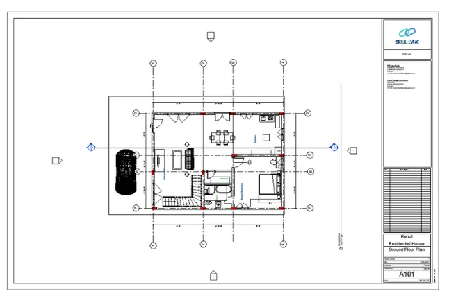
b. 102 - Architecture plan of the first floor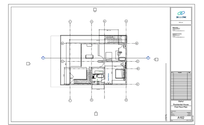
. A 103- Plan of the roof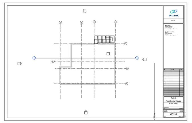
A-201- North-South Elevation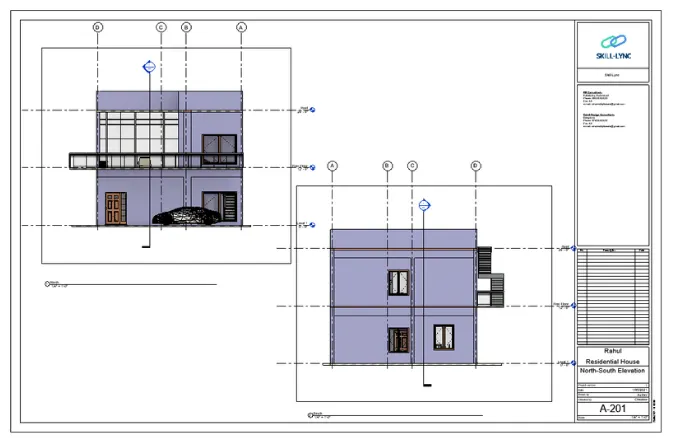
. A-202- East-West altitudes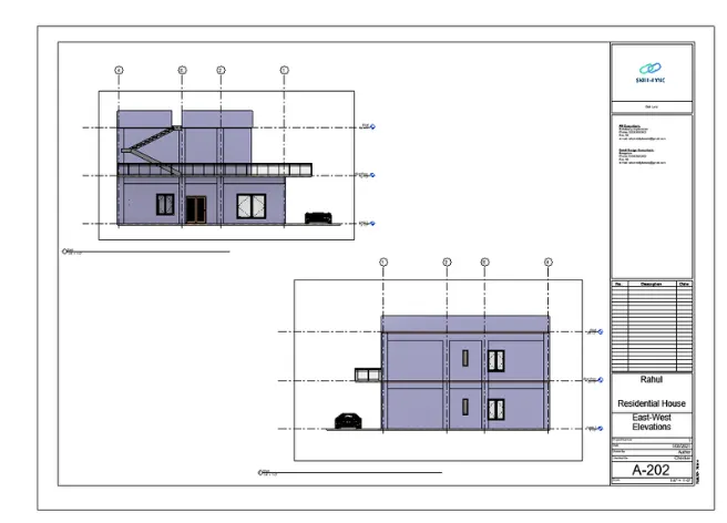
C-101-Ceiling Plans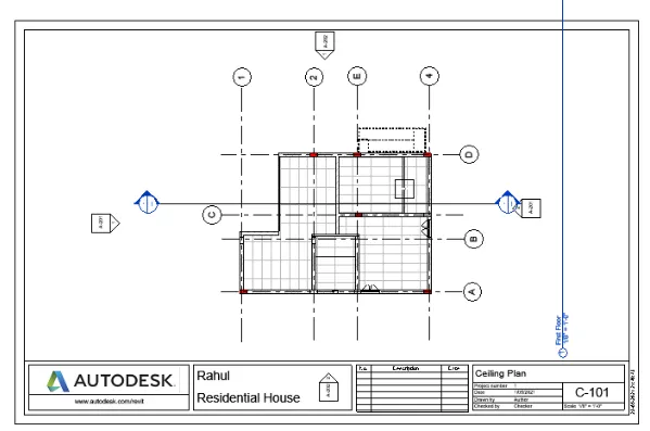
question 10
aim: Create multiple sheets for different views
Introduction:
In Revit, you create a sheet view for each sheet in the design document set. You can then place multiple drawings or plans on each sheet view. About Tables in project templates. Before you start building the model, create views on the project template to simplify the project documentation process.
Method:
Step 1: Create a 3D Cam View
Go to the View tab
Click on 3D View and click on Camera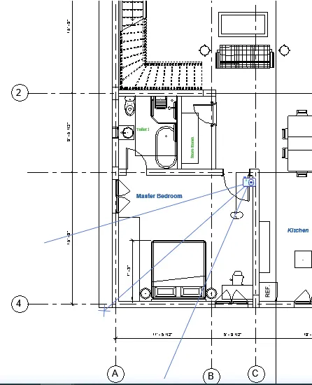
Set the Camera Point to the desired location and indicate the direction of the camera as shown in the image
Step 2: Add views to the template
Go to the project browser
Click on Tables (all)
Right-click to add a new sheet or
Click + to open previously made sheets
Right click on the sheet to add a sheet view as shown below
Result:
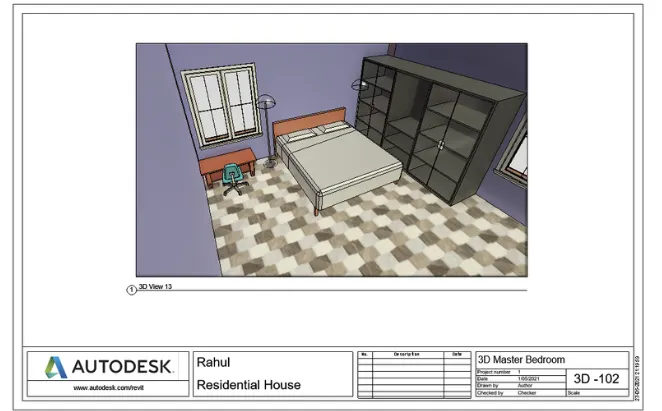
Following are the different 3D Cam views created in prokect
A. 3D-101- 3D living room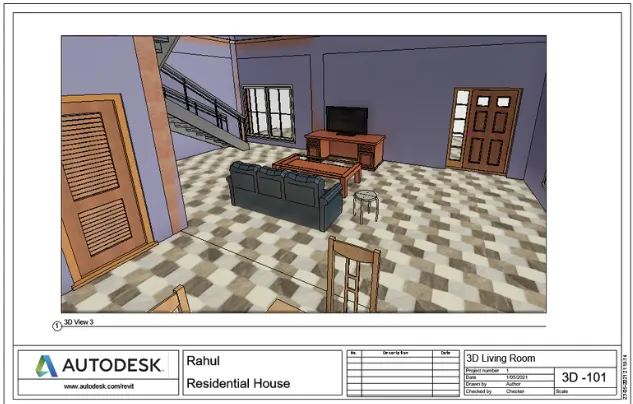
B. 3D-102- 3D master bedroom
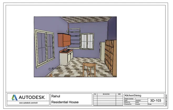
c.3d kitchen