3D Creation of Celing, Roof, Architectural plan, Structural plan, Sectional view, Elevation view and Camera specific view for a house plan using REVIT
1)
AIM:- Based on the project saved from Week 3, proceed from the First Floor Level. Model a Ceiling from the architecture tab above the walls at the first-floor level
PROCEDURE:-
- For the creation of the ceiling open the drawing.
- Go to the respective floor plan on which the ceiling is to be constructed.
- Now go to the architecture toolbar and select the "CEILING" option.

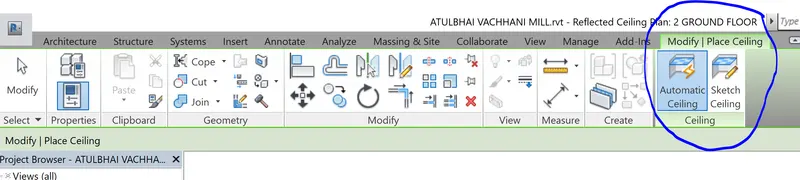
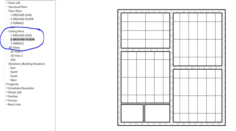
- Now after selecting the type of the ceiling put the ceiling on the desired room and give it the base height and select the needed material.
---------------------------------------------------------------------------------------------------------------------------------
2)
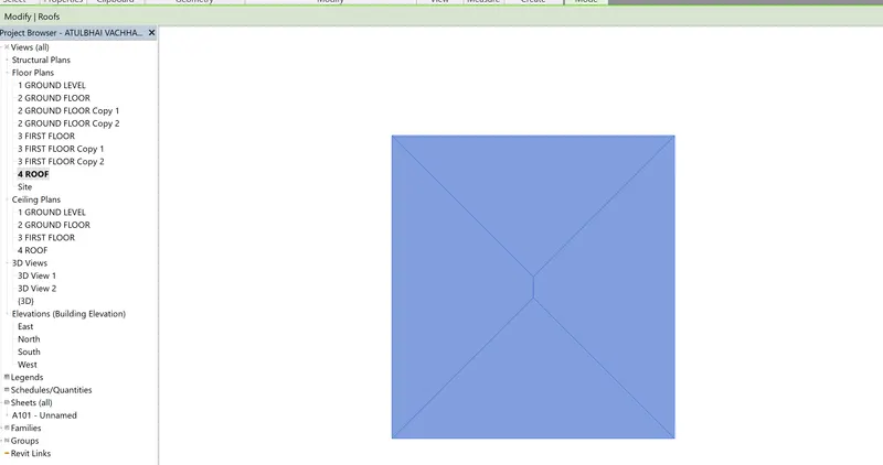
AIM:- Model a roof above the ceiling by selecting the footprints of the ceiling. Using the adjustment toolbars appearing on-screen adjust the roof slope to 10 degrees
PROCEDURE:-
- For the creation of the ROOF open the drawing.
- Go to the respective floor plan on which the roof is to be constructed.
- Now go to the architecture toolbar and select the "ROOF" option.
- Now select the roof by footprint option to create a roof.


- Now using the above tools create a roof of the desired shape.
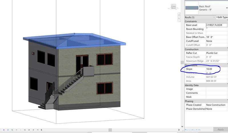
- Now after creation of the roof go to the properties to give the slope of 10 to the roof.
- Now simply enter the value 10 in the slope box and the roof slope of 10 is created.
---------------------------------------------------------------------------------------------------------------------------------
3)
AIM:- Using the file saved from weeks 2 to 4, create plan views for ground floor level and first-floor level including all the walls, floors, and components. Separate them to architecture and structural plans
PROCEDURE:-
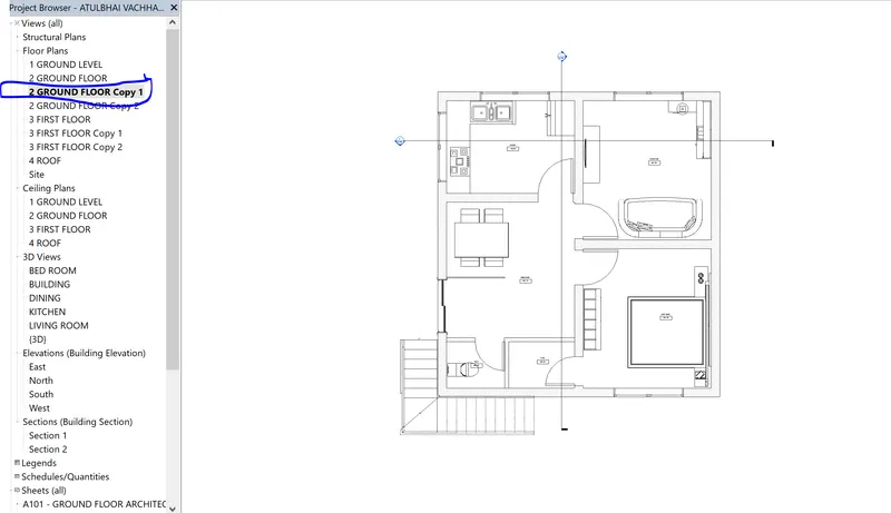
- For the creation of the architectural plan and structural plan create a duplicate view of the respective floor plan.
- For the creation of the duplicate view go to the project browser and then right click on the floor of which duplicate is to be created
- Now select the duplicate from the appeared dialogue box.
- Now the duplicate view is created.
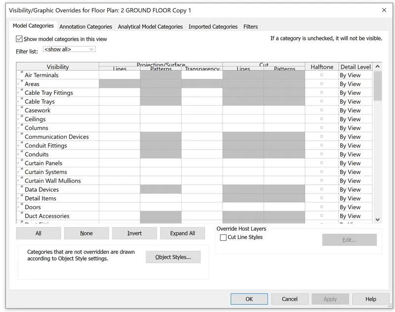
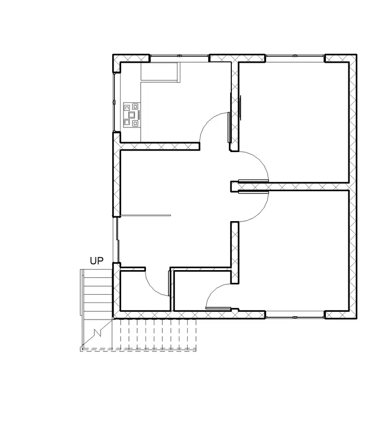
- Now for the structural drawing create another duplicate view and then use the visuality graphics options to disable the unwanted options to show only structural elements.
---------------------------------------------------------------------------------------------------------------------------------
4)
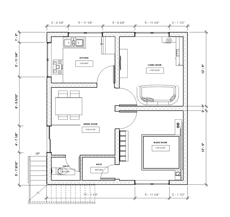
AIM:- Using annotate toolbar add dimensions to all the walls and floors with reference to the longitudinal and transverse grids created in the project file
PROCEDURE:-
- for the dimension go to the annotate toolbar.
- select the aligned option and then enter the dimensions whereever needed.

----------------------------------------------------------------------------------------------------------------------------------
5)
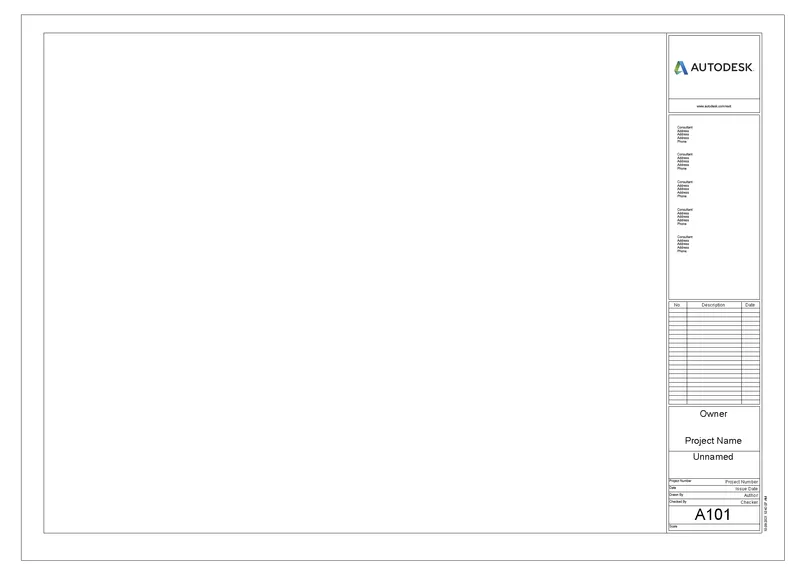
AIM:- Create a sheet template from the view tab and adjust the parameters on the sheet to add appropriate views
PROCEDURE:-
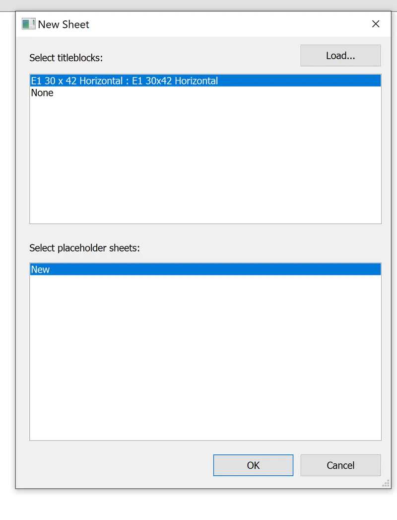
- For the creation of the sheet go to the view toolbar
- Now select the sheet option in the view tool bar.
- After selecting the sheet option select the sheet from the appeared dialogue box.
- Hence sheet is created.

---------------------------------------------------------------------------------------------------------------------------------
6)
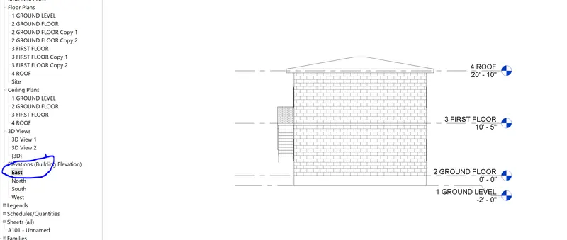
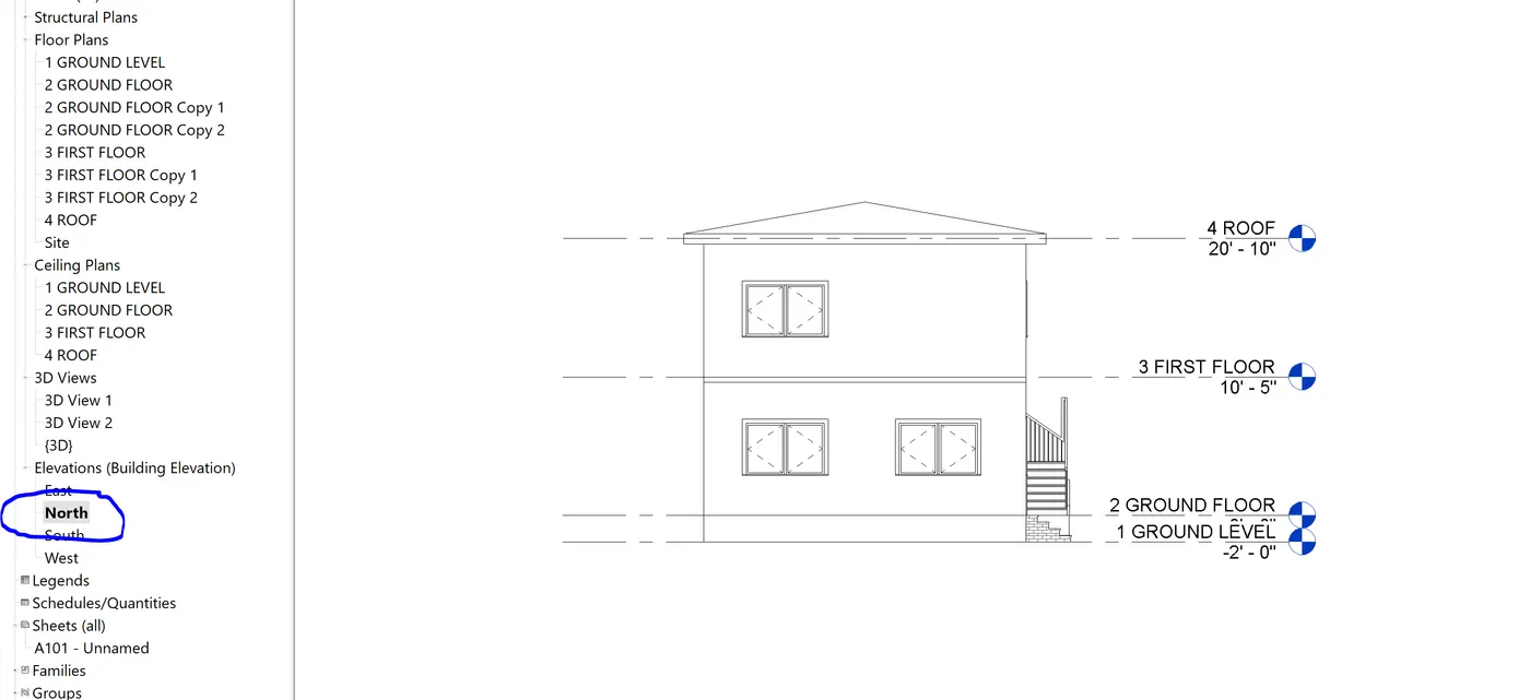
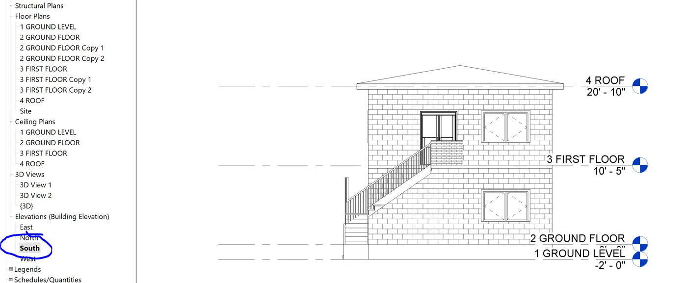
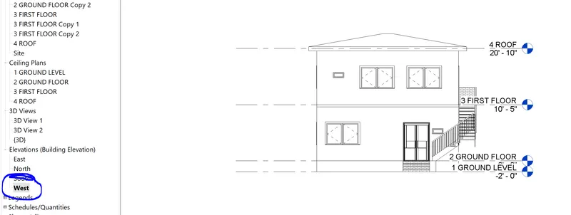
AIM:- Using the elevation tab create the elevation views, looking at your building from East, North, South, and West
PROCEDURE:-
- For the creation of the elevation go to the project browser tab and then go to the elevations.
- In elevations east, west, north, south following elevations will be created.
- East.
- North.
- South.
- West.
-----------------------------------------------------------------------------------------------------------------------------------
7)
AIM:- Produce section cut through each room either cutting across longitudinally or in a transverse direction
PROCEDURE:-
- For the creation of the section go to the view tool bar.
- Now select the section option from the draw tool bar.
- Now draw the section line in the floor plan as needed Vertical/Horizontal.

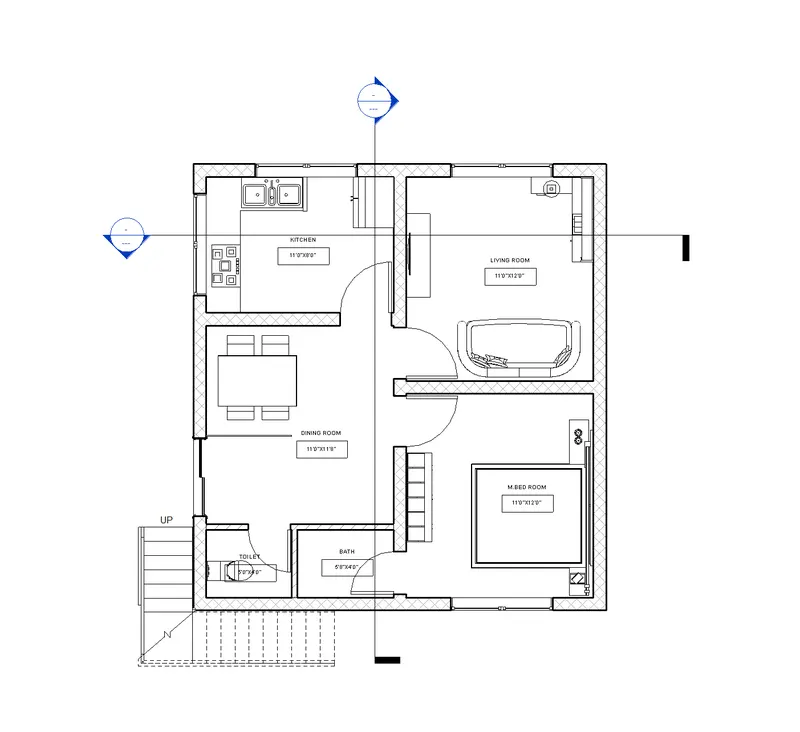
- Now for seeing the created section go to the project browser.
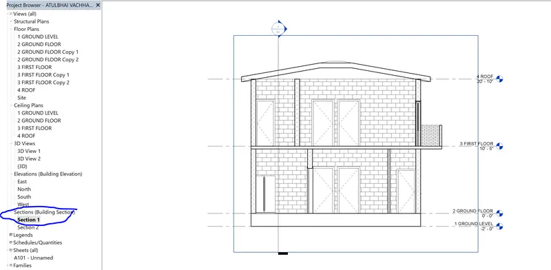
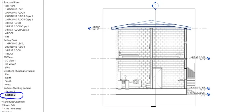
- Now select section in the project browser and the created sections will be shown.
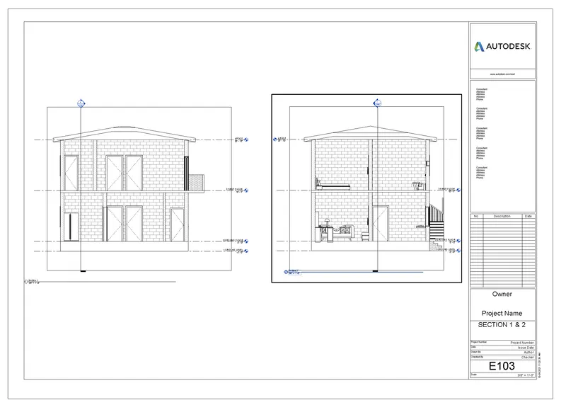
- Section 1
- Section 2
------------------------------------------------------------------------------------------------------------------------------------
(9 & 10)
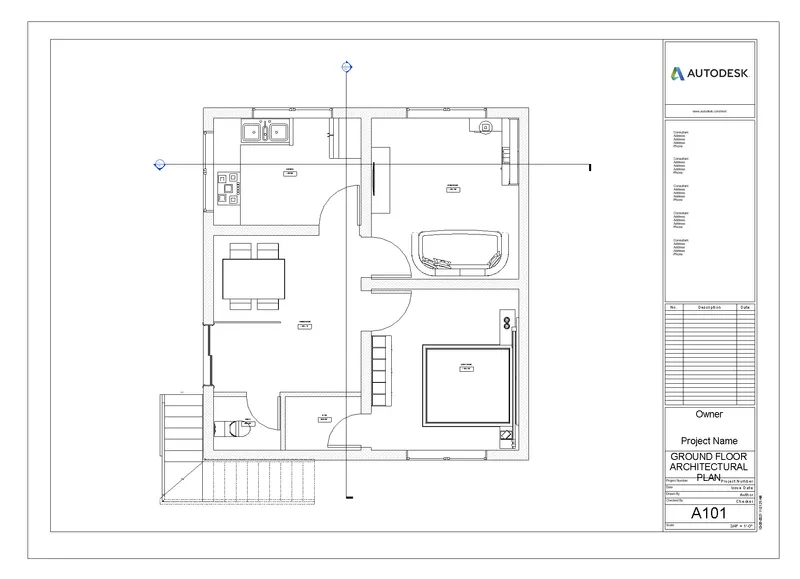
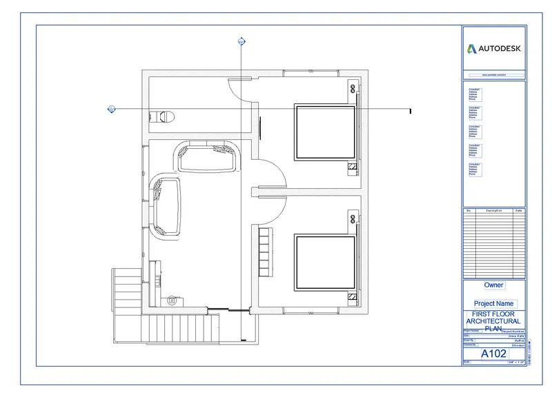
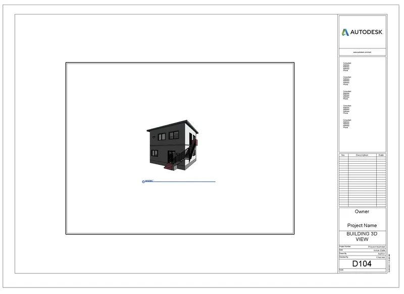
For the creation of the respective sheets go to the sheet then drag and drop the respective view to be taken in the sheet and then arrange the Scale as needed and hence the sheet is created. Following are the sheets which are created in the revit.
- A101 - Ground floor Architectural plan.
- A102 - First floor architectural plan.
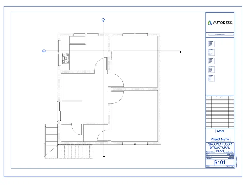
- S101 - Ground floor structural plan.
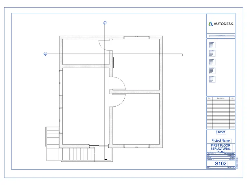
- S102 - First floor Structural plan.
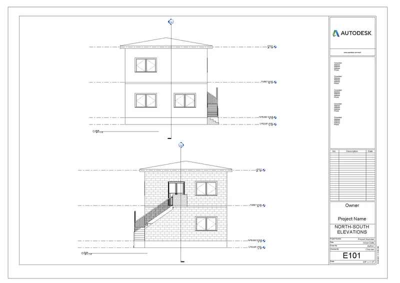
- E101 - North-South Elevation.
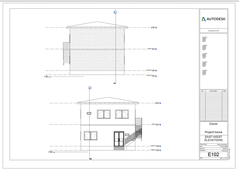
- E102 - East-West Elevation.
- E103 - Section 1&2
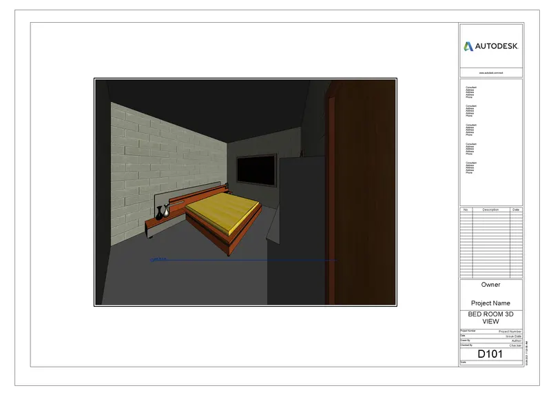
- D101 - Bedroom 3D view
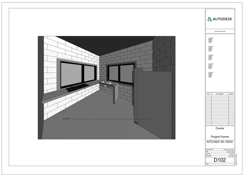
- D102 - Kitchen 3D view
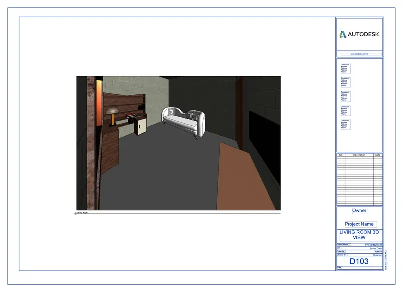
- D103 - Livingroom 3D view
- D104 - Building 3D view
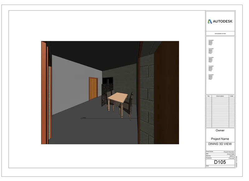
- D105 - Dining 3D view