3D Creation of Celing, Roof, Architectural plan, Structural plan, Sectional view, Elevation view and Camera specific view for a house plan using REVIT
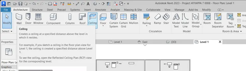
Q1) Based on the project saved from Week 3, proceed from the First Floor Level. Model a Ceiling from the architecture tab above the walls at the first-floor level
AIM :
To proceed from the First Floor Level. Model a Ceiling from the architecture tab above the walls at the first-floor level
INTRODUCTION :
- In this Revit Architecture tutorial, I am going to show you how to create Ceiling elements both “Automatically” and by means of the “sketch method”.
TYPES OF DRAWING:
- Creating Ceilings automatically
- Creating Ceilings by Sketch
- Aligning Suspended Ceiling Grids
Just like Floors and Roofs, Revit Ceilings consist of 3D model geometry and non-graphical parametric data. They are created by use of the dedicated Ceiling tool. There are 2 methods of creating Ceilings- each with their own pros and cons, which I will explain at the end of the tutorial. To make this tutorial a little more realistic, I have created a simple building to which we can add some Ceiling elements…..
If we take a look at this model from the side (using an Elevation View), you can see that it has 3 Levels. I have created a dedicated Level for the Ceiling Heigh
Before we actually create any Ceilings, switch to a Ceiling Plan VieW
PROCEDURE :
- Open a new sheet and set units as feet and inchs,
- Taken the ceiling area by selecting use of project browser
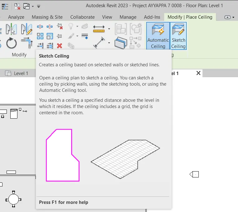
- In above the tool bar, click the ceiling option and make the drawing
- set into the floor plan using ceiling on project browser
- And use the sketch option or automatic option to draw the ceiling
- If you can use the sketch option please use a rectangle or line option to easy draw
- I can take rectangle option here and draw with rectangle in inner of the walls.
- After draw the ceiling, give the offset height of the celing if you want
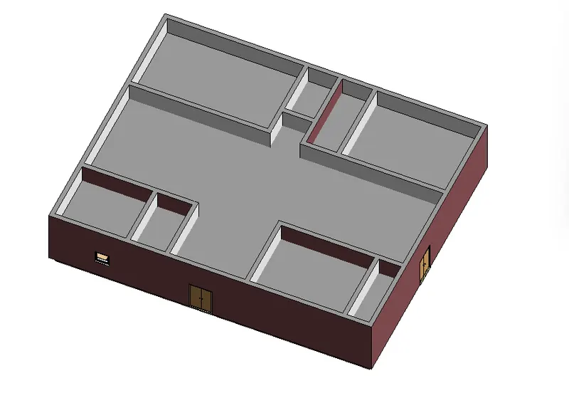
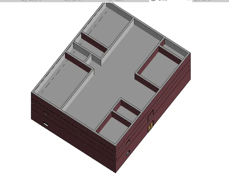
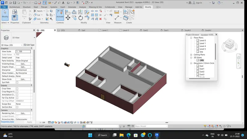
- finally just click ok, and check into in 3d option.
RESULT :
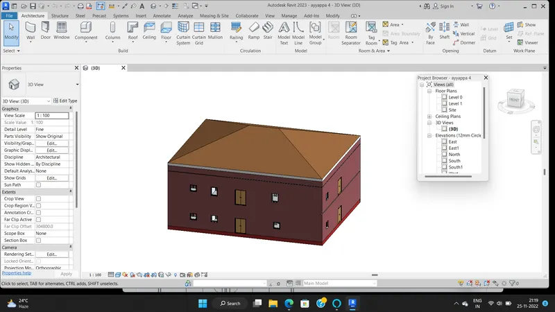
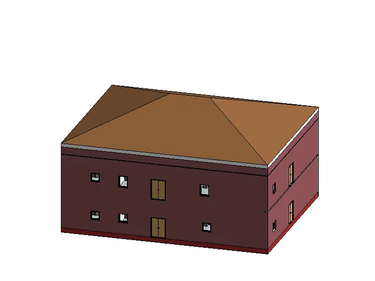
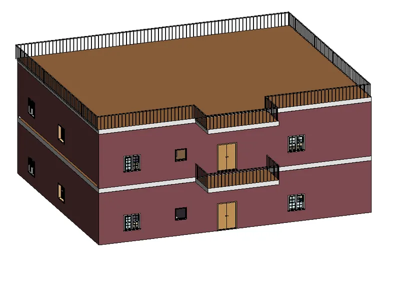
Q2) Model a roof above the ceiling by selecting the footprints of the ceiling. Using the adjustment toolbars appearing on-screen adjust the roof slope to 10 degrees
AIM :
To Model a roof above the ceiling by selecting the footprints of the ceiling. Using the adjustment toolbars appearing on-screen adjust the roof slope to 10 degrees
INTRODUCTION :
- Revit offers several methods of creating roofs. Choose the method that best meets the needs of your design. About Start and End Points for Extruded Roofs.
- The extrusion of a roof can extend in either a positive or a negative direction along the plane perpendicular to the face of a solid component (such as a wall)
- Create roofs on any non-vertical faces of a mass using the Roof by Face tool. You can create roofs in a similar way that we created floors (refer to my previous blog on the Cadline Community.
- In the Type Selector, select a roof type.
- Move the cursor to highlight a face.
PROCEDURE :
- The process is little same like as ceiling procedure but here we have use the roof option
- open a new sheet and set units
- In the tool bar taken a roof option
- we have to select the foot print in roof option
- And pick the same as automatic or sketch
- As per the same i can take a sketch option for draw the roof
- After taken the rectangle option just draw in exterior wall
- In the properties browser given the slope value as 10 degree.
- And click ok,
- finally check the roof in 3d views
RESULT :
Q3) Using the file saved from weeks 2 to 4, create plan views for ground floor level and first-floor level including all the walls, floors, and components. Separate them to
architecture and structural plans
a. Architecture plan must have walls, floors, and all the components placed within the building
b. Structure plan must have details of only walls, floors, and columns
AIM :
To Using the file saved from weeks 2 to 4, create plan views for ground floor level and first-floor level including all the walls, floors, and components. Separate them to architecture and structural plans
INTRODUCTION :
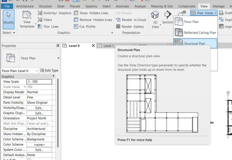
- The structural plan view is the default view when you start a new project using a structural template.. Most projects include at least one structural plan. New structural plan views are created automatically as you add new levels to your project. You can create multiple structural plan view types
-
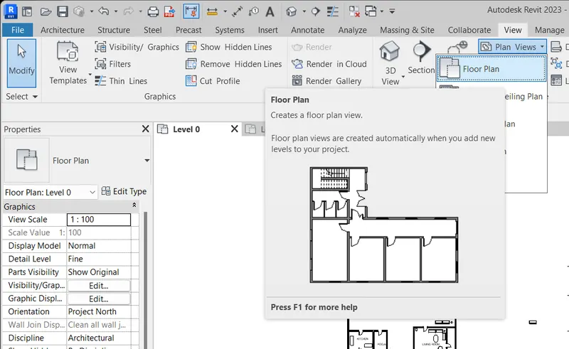
The floor plan view is the default view in a new architectural project. - Most projects include at least one floor plan.
-
Floor plan views are created automatically as you add new levels to your project.
PROCEDURE :
a. Architecture plan must have walls, floors, and all the components placed within the building
- Open the new sheet and set the unit
- set the levels
- In the above tool bar pick the view option
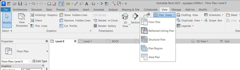
- And taken the plan views in right side
- In the plan views they have some option just pick the floor plan
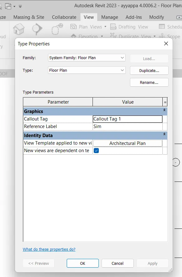
- And click the edit option, set the architecture
- And click ok, to view the architecture plan on screen
b. Structure plan must have details of only walls, floors, and columns:
- Same like as above option
- Open the new sheet and set the unit
- set the levels
- In the above tool bar pick the view option
- And taken the plan views in right side
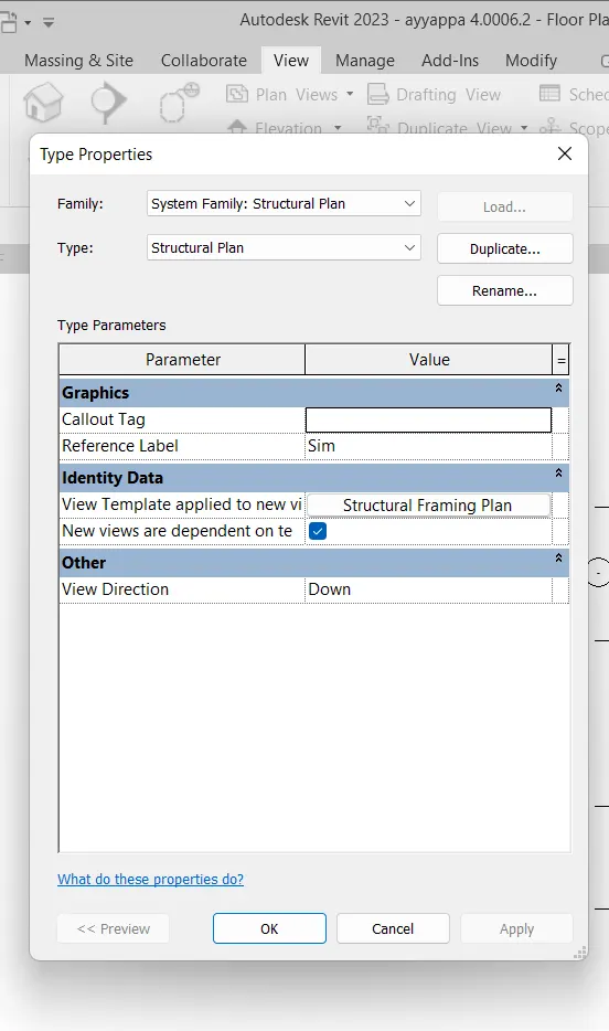
- In the plan views they have some option just pick the structural plan
- Automatically it can show the structural view in the plan
RESULT :
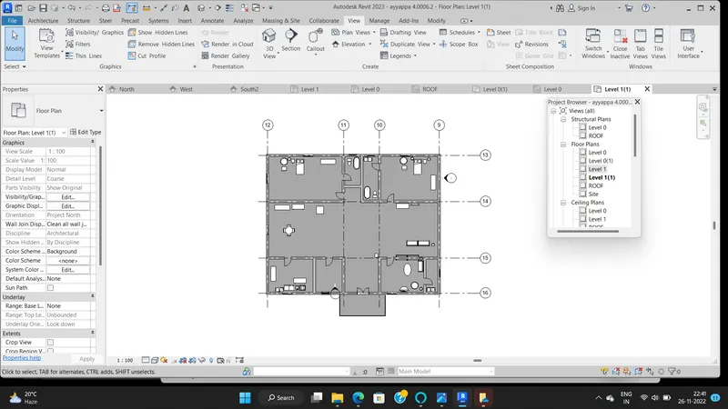
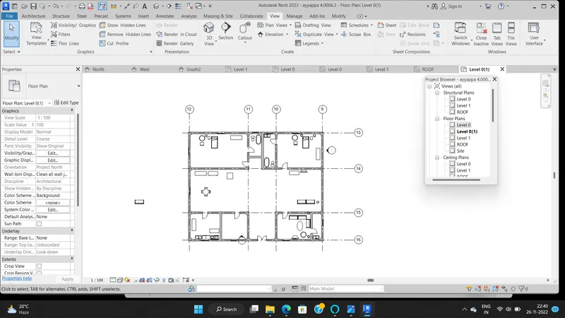
a.) finally architectural view as been submitted
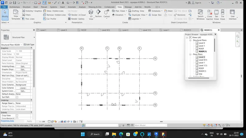
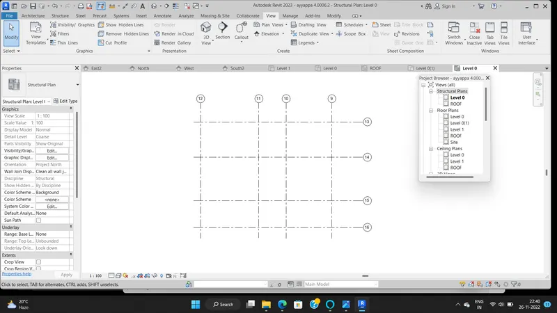
a.) finally structural view as been submitted
Q4) Using annotate toolbar add dimensions to all the walls and floors with reference to the longitudinal and transverse grids created in the project file
a. The architecture plan dimensions include details on where the components are placed within the buildings with relation to grids. Overall dimensions are sufficient for architecture plans
b. The Structure plan dimensions must include details on the position of all the walls and interior walls with reference to grids. Locate all the framing components of the building with reference to a fixed point using Structural plans
AIM :
To Using annotate toolbar add dimensions to all the walls and floors with reference to the longitudinal and transverse grids created in the project file
INTRODUCTION :
- A tag is an annotation for identifying elements in a drawing. Symbols. A symbol is a graphic representation of an annotation element or other object. Multi-Rebar Annotations. Tag multiple rebar and rebar sets with a single annotation.
- In a view that shows the main model and a design option, add the annotations and details that you want to appear in similar views for all design options.
- With the view active in the drawing area, click View tab Create panel Duplicate View drop-down (Duplicate with Detailing).
Annotate and Detail Design Options
Grids in Revit?
- Grids are annotation elements that help organize your design. On the ribbon, click (Grid). Click Modify | Place Grid tab Draw panel and select a sketch option. Use (Pick Lines) to snap the grid to an existing line, such as a wall
PROCEDURE :
- Same like as above option
- Open the new sheet and set the unit
- set the levels in elevation view
- In the tool bar pick the modify option
- And they have many option to pick in modify tool bar
- We can taken the linear option to draw the dimenstion
- just drag the one wall to another wall for show the dimension
- Give the dimensions for separate separate individual rooms


RESULT :
a. The architecture plan dimensions include details on where the components are placed within the buildings with relation to grids. Overall dimensions are sufficient for architecture plans
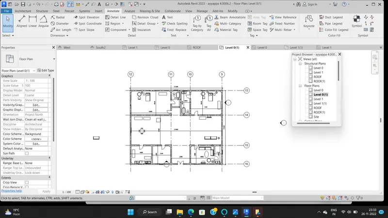
b. The Structure plan dimensions must include details on the position of all the walls and interior walls with reference to grids. Locate all the framing components of the building with reference to a fixed point using Structural plans
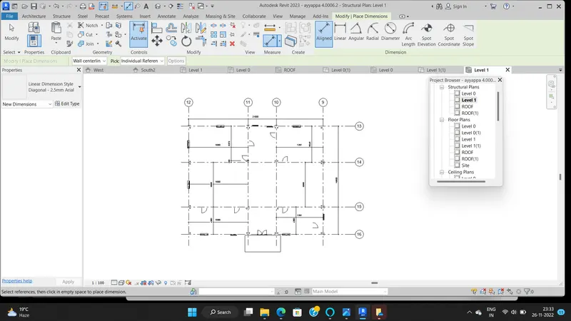
Q5) Create a sheet template from the view tab and adjust the parameters on the sheet to add appropriate views
AIM :
To Create a sheet template from the view tab and adjust the parameters on the sheet to add appropriate views
INTRODUCTION :
- A construction document set (also called a drawing set or a sheet set) consists of several sheets. Topics in this section. About Sheets. In Revit, you create a sheet view for each sheet in the construction document set.
- You can then place multiple drawings or schedules on each sheet view.
Add sheet :
- Open the project.
- Click View tab Sheet Composition panel (Sheet).
- Select a title block, as follows: In the New Sheet dialog, select a title block from the list. ...
- Enter information in the title block of the sheet.
- Add views to the sheet.
- Change the default number and name that Revit assigned to the sheet.
PROCEDURE :
- Open the new sheet and set the unit
- set the levels
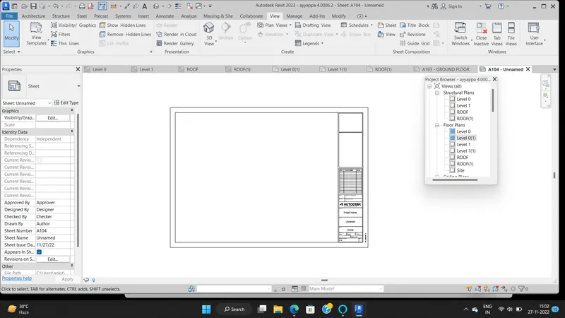
- select the sheet option in the above tool bars.
- Edit the sheet size as what you want like ( A0, A1, A2, A3, A4 ).
- I can take the A2 sheet
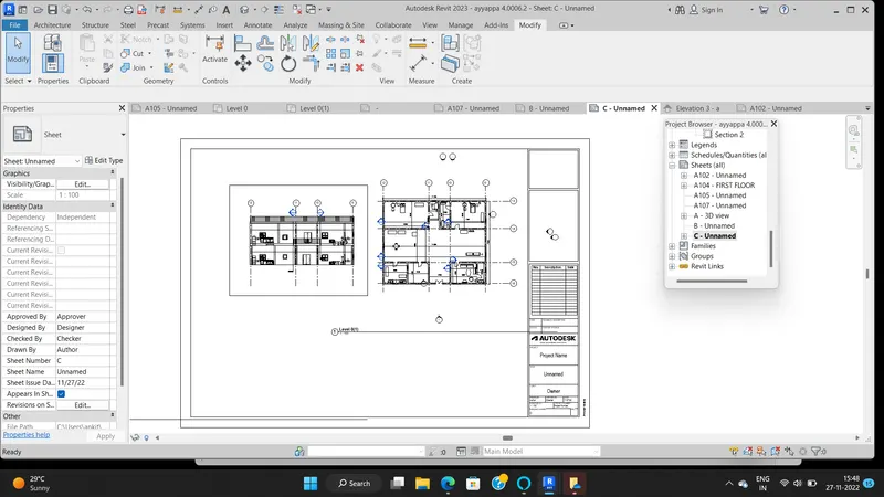
- And pick the floor plan and drag into the sheet.
- And edit the size of the picture use the scale option in properties box.
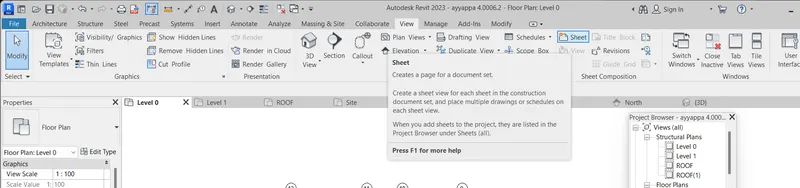
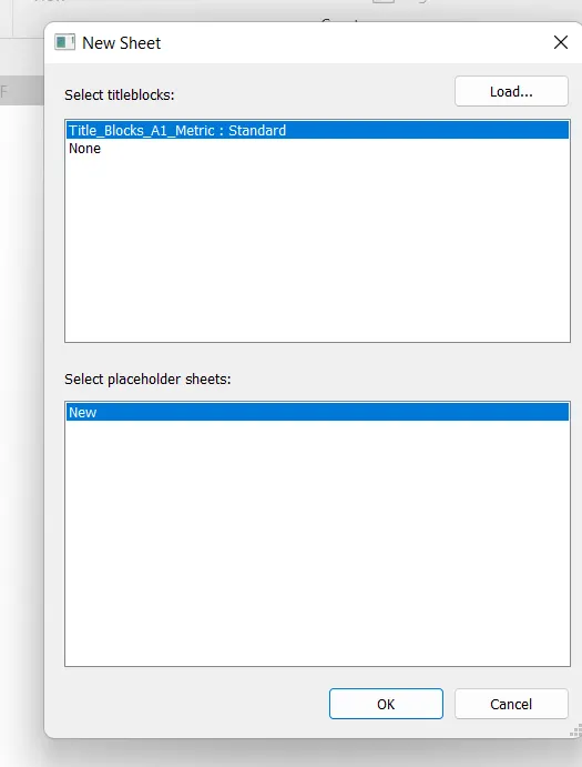
RESULT :
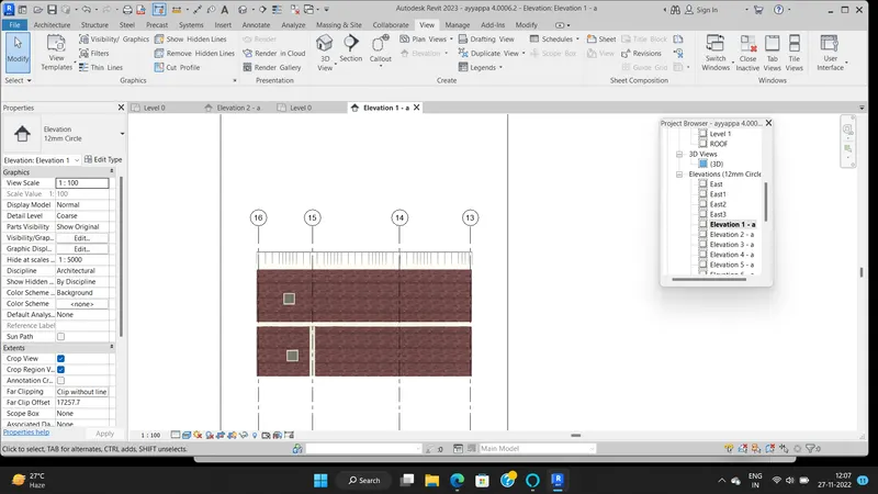
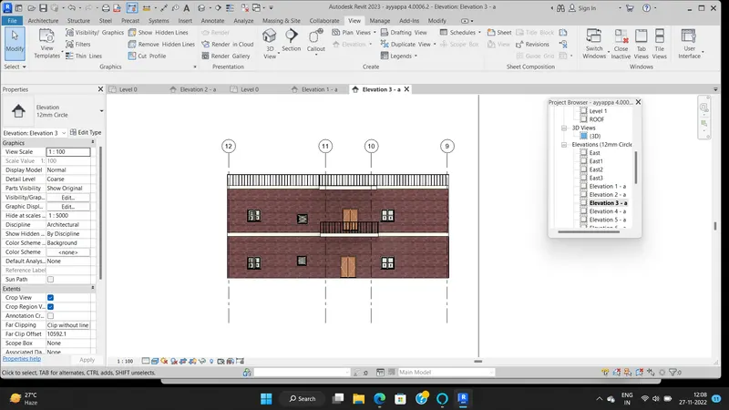
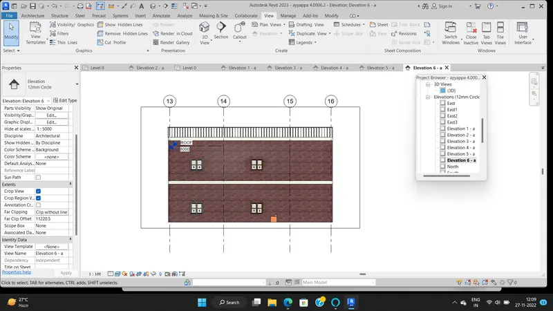
Q6) Using the elevation tab create the elevation views, looking at your building from East, North, South, and West
AIM :
To Using the elevation tab create the elevation views, looking at your building from East, North, South, and West
INTRODUCTION :
- An elevation drawing is a view of a building seen from one side. ... Elevations are drawn as if looking at a building from the front or side (as opposed to floor plans which are drawn looking at a building from above) and provide the viewer with an idea of how the final building will appear.
- Elevation views are part of the default template in Revit Architecture.
- When you create a project with the default template, 4 elevation views are included: north, south, east, and west. It is in elevation views where you sketch level lines. For each level line that you sketch, a corresponding plan view is created.
PROCEDURE :
- Open the new sheet and set the unit
- set the levels
- After finishing the diagram in 3d model
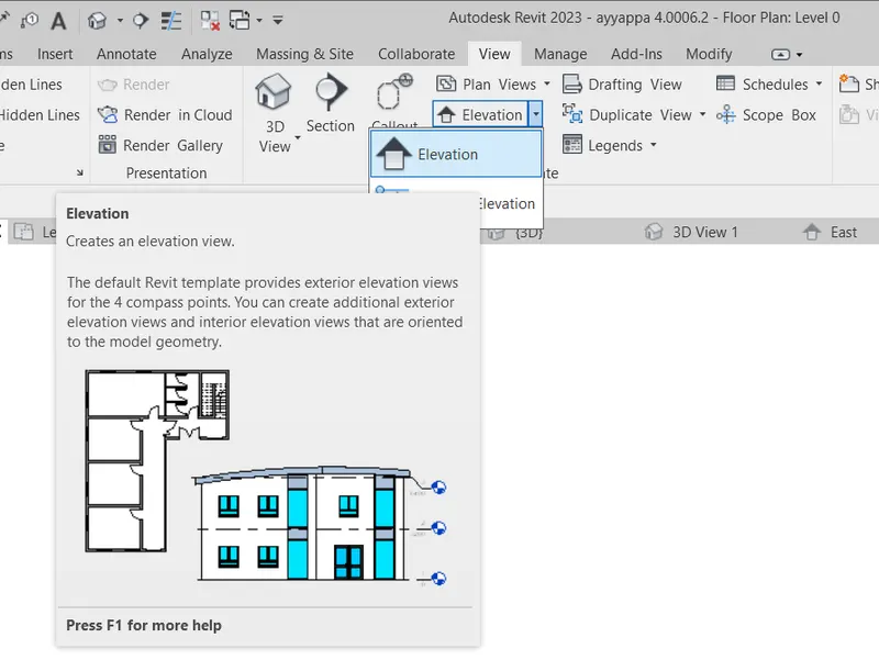
- pick the elevation in above the tool bar
- After taken the elevation option and place into in the screen
- it place depends upon the diagram
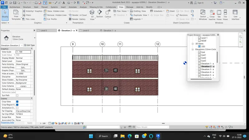
- we can placed the elevation in four side north, south, east, west
- just check the elevation in project browser

RESULT :
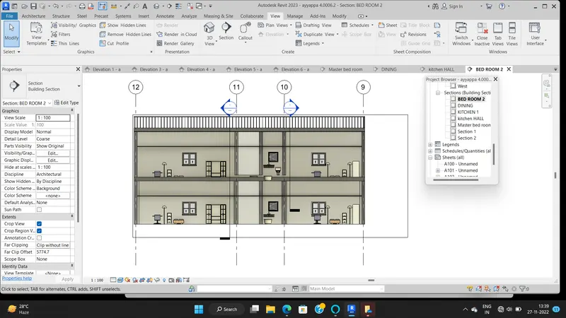
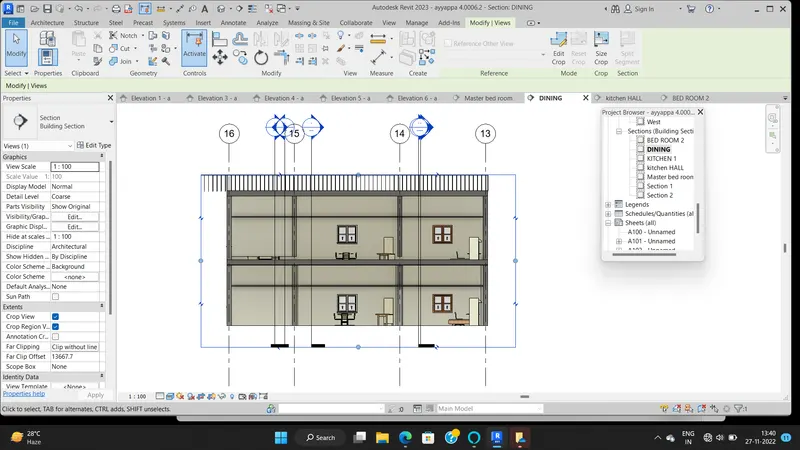
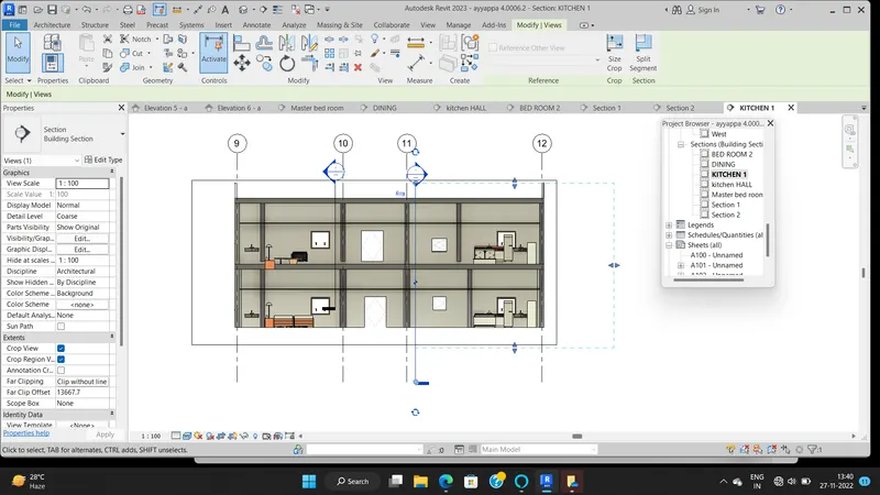
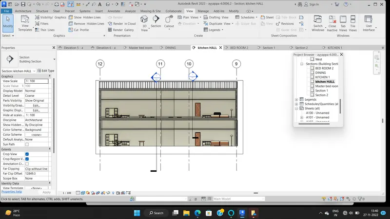
Q7) Produce section cut through each room either cutting across longitudinally or in a transverse direction
AIM :
To Produce section cut through each room either cutting across longitudinally or in a transverse direction
INTRODUCTION :
-
Sectional views reveal hidden details in a mechanical drawing.
-
These views assume that a cutting plane has removed portions of the object represented by the drawing, displaying the appropriate section of the interior.
-
Sectional views are used in engineering and architectural drawings.
-
They help civil engineers, architects, and airplane designers communicate their ideas to their peers.
PROCEDURE :
- Open the new sheet and set the unit
- set the levels
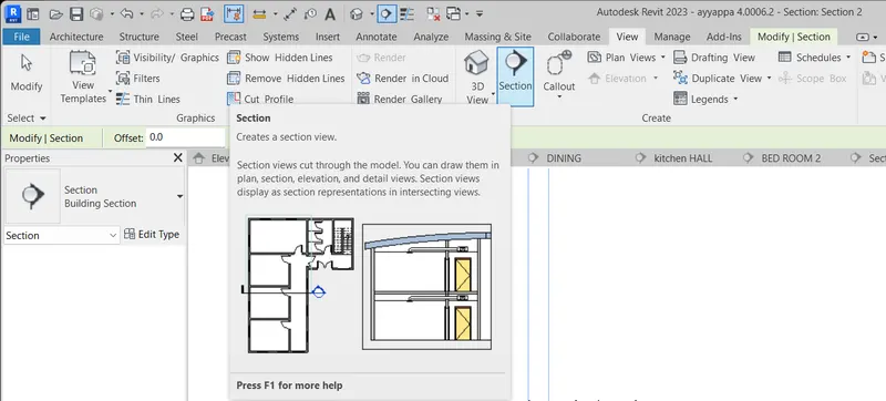
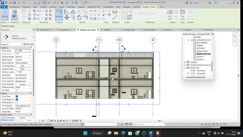
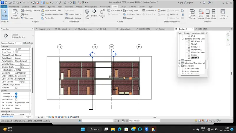
- taken the section option in above the tool bar.
- And section option is make cut the elevation and view the cutting elevation on the screen
- Create the section view with use of section option
- And cut the plan view with use of section
- And saw the section in the section view on project browser
- check on the 3d view with use of section in project browser
RESULT :
Q8) Classify the views, Plan Views, Section Views, and Elevation views to either Design or Documentation category using Properties browser
AIM :
To Classify the views, Plan Views, Section Views, and Elevation views to either Design or Documentation category using Properties browser
INTRODUCTION :
- The structural plan view is the default view when you start a new project using a structural template.
- Most projects include at least one structural plan. New structural plan views are created automatically as you add new levels to your project. You can create multiple structural plan view types
- The floor plan view is the default view in a new architectural project. Most projects include at least one floor plan.
- Floor plan views are created automatically as you add new levels to your project. Sectional views reveal hidden details in a mechanical drawing
- These views assume that a cutting plane has removed portions of the object represented by the drawing, displaying the appropriate section of the interior.
- Sectional views are used in engineering and architectural drawings
- They help civil engineers, architects, and airplane designers communicate their ideas to their peers.
- An elevation is a view of a building seen from one side, a flat representation of one view.
- This is the most common view used to describe the external appearance of a building
- Each elevation is labelled in relation to the compass direction it faces, eg. looking toward the north you would be seeing the southem elevation of the building.
PROCEDURE :
- Open the new sheet and set the unit
- set the levels
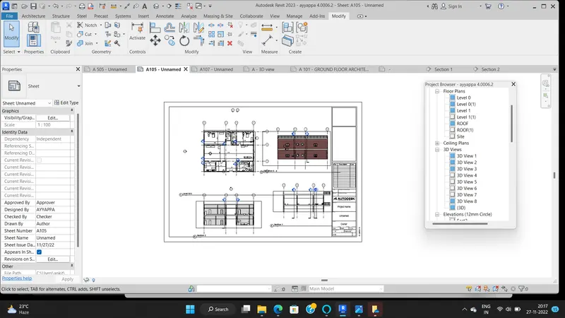
- use the sheet option in views on tool bar
- set new sheet and modify the size
- Taken the ground floor and drag into the sheet and modify the size with use of scale
- Taken the first floor and drag into the sheet and modify the size with use of scale
- Taken the section plan and drag into the sheet and modify the size with use of scale
- Taken the elevation and drag into the sheet and modify the size with uses of scale
RESULT :
Q9) Using the sheet template produced create multiple sheets as follows
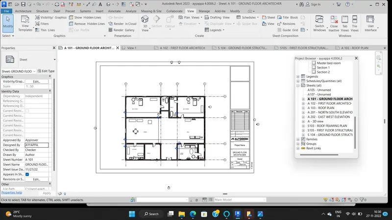
a. A 101- Ground Floor Architecture Plan
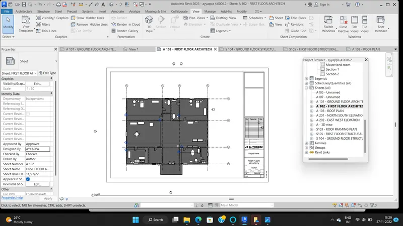
b. A 102- First Floor Architecture Plan
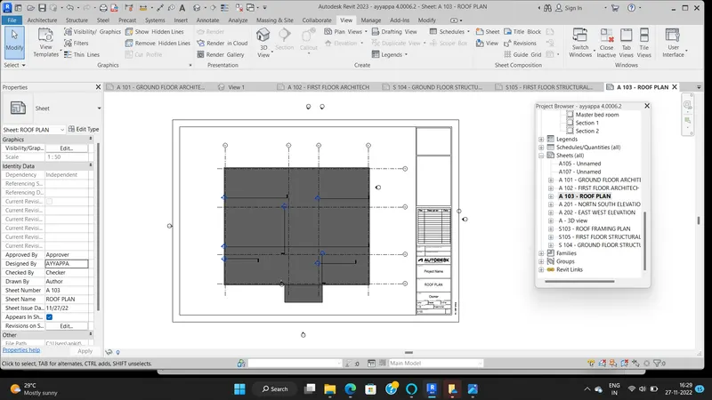
c. A 103- Roof Plan
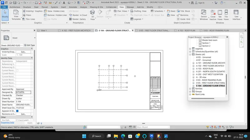
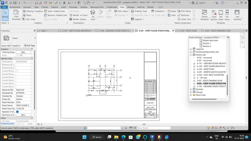
d. S 101- Ground Floor Structural Plan
e. S 102- First Floor Structural Plan
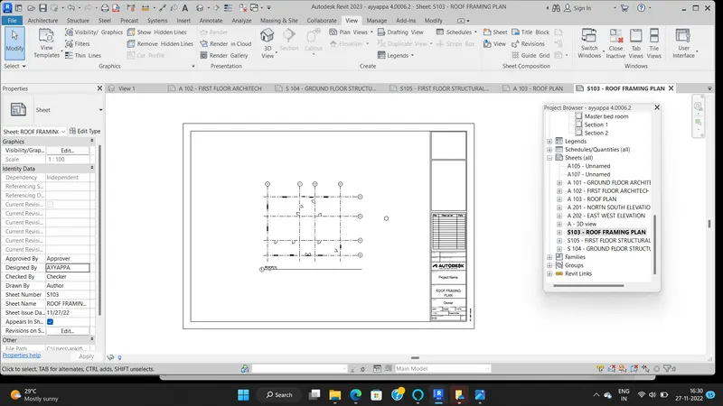
f. S 103- Roof Framing Plan
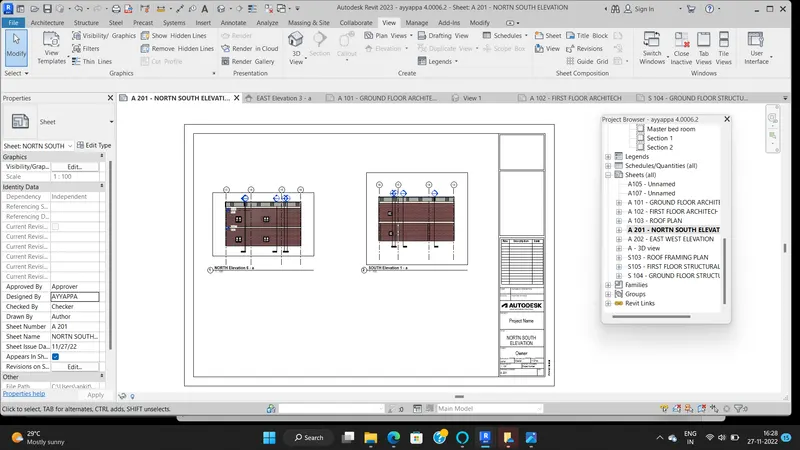
g. A-201- North-South Elevations
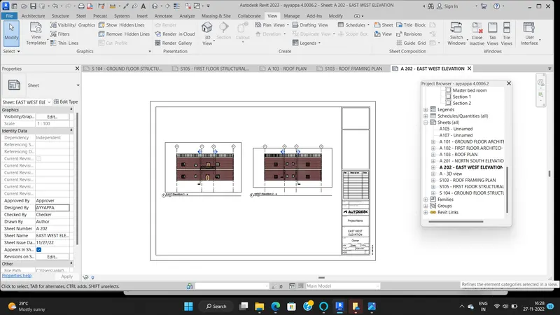
h. A-202- East-West Elevations
Add additional sheets based on the sections created in your Revit file
AIM :
To Using the sheet template produced create multiple sheets as follows
INTRODUCTION :
- When a view is too large to fit on a single sheet, you can create multiple sheets for the view, divide the view into parts, and show one part on each sheet. You can also use this technique when a view is too tall or wide for a sheet, and you want to show parts of the view next to each other on the same sheet.
-
Add a Sheet
- Open the project.
- Click View tab Sheet Composition panel (Sheet).
- Select a title block, as follows: In the New Sheet dialog, select a title block from the list. ...
- Enter information in the title block of the sheet.
- Add views to the sheet.
- Change the default number and name that Revit assigned to the sheet.
PROCEDURE :
- Open the new sheet and set the unit
- set the levels
- use the sheet option in views on tool bar
- set new sheet and modify the size
- Here we can also set the name and number of the sheet individually
- Here we have 8 number of different sheet want to create as followed by the given questions
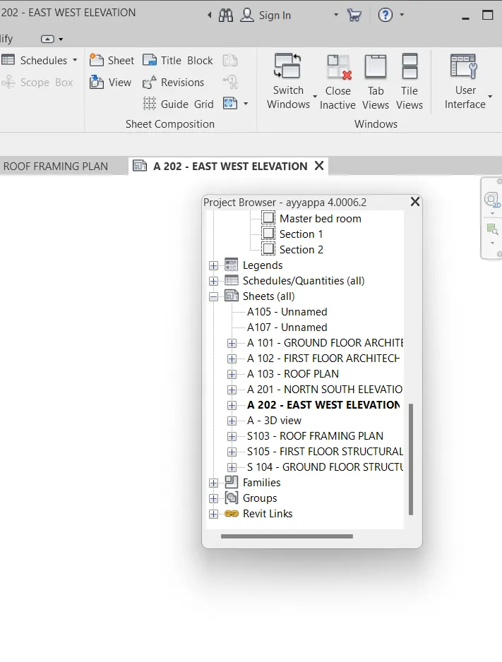
- In the project browser we can see the sheet options and alredy created sheets are shown here
- just select the one by one sheet
- First we can taken the A-101 - ground floor architecture plan sheet and drag the architecture floor plan into the sheet and modify the size of the diagram.
- Next we can taken the A-102 - first floor architecture plan sheet and drag the architecture first floor plan into the sheet and modify the size of the diagram.
- Next we taken the A-103 - Roof plan sheet and drag the roof plan into the sheet and modify the size of the diagram.
- Next we taken the A-201 - north-south elevation sheet and drag the North-south elevation into the sheet and modify the size of the diagram.
- Next we taken the A-202 - east-west elevation sheet and drag the east-west elevation into the sheet and modify the size of the diagram.
- Next we taken the S-101 - ground floor structural plan sheet and drag the ground floor structural plan into the sheet and modify the size of the diagram.
- Next we taken the S-102 - first floor structural plan sheet and drag the structural first floor plan into the sheet and modify the size of the diagram.
- Next we taken the S-103 - roof farming plan sheet and drag the roof farming plan into the sheet and modify the size of the diagram.
RESULT :
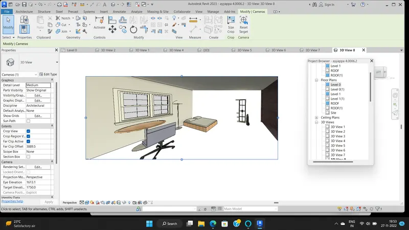
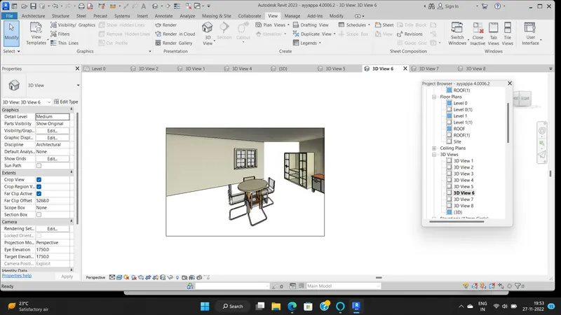
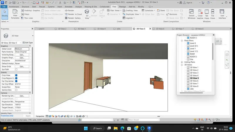
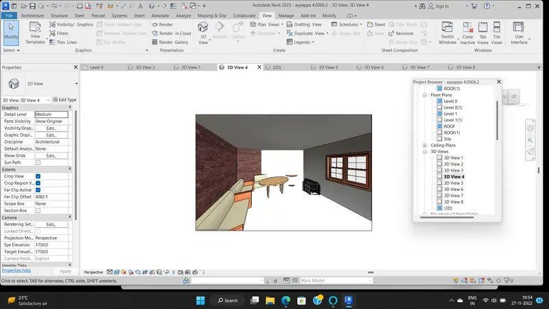
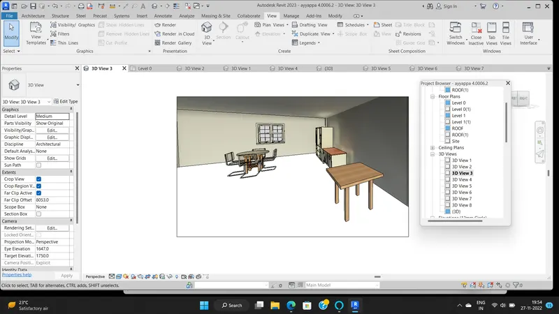
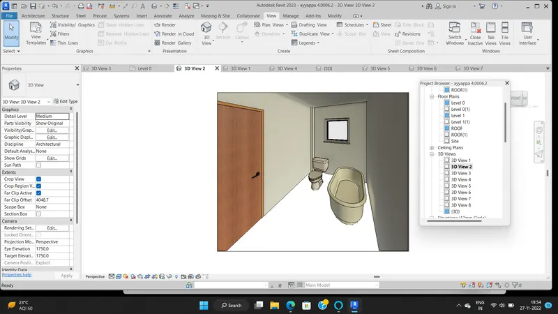
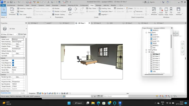
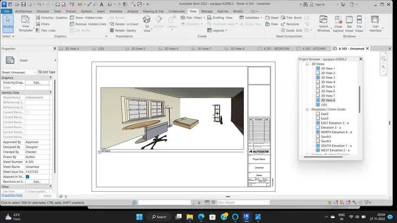
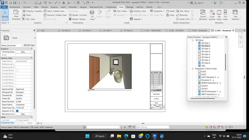
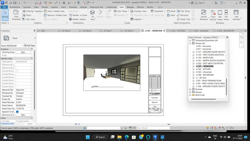
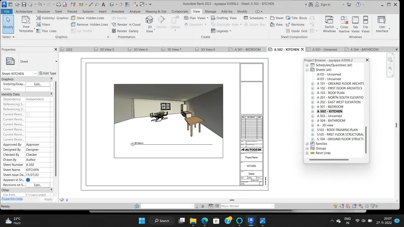
Q10) Create a camera-specific view or a 3D view in each room ( living, dining, bedroom). Based on the views create a new set of sheets starting A-501 (you can add as many sheets after, 502, 503.. n)to place the 3D view images. Produce the sheets as a part of project drafting.
AIM :
To Create a camera-specific view or a 3D view in each room ( living, dining, bedroom). Based on the views create a new set of sheets starting A-501 (you can add as many sheets after, 502, 503.. n)to place the 3D view images. Produce the sheets as a part of project drafting.
INTRODUCTION :
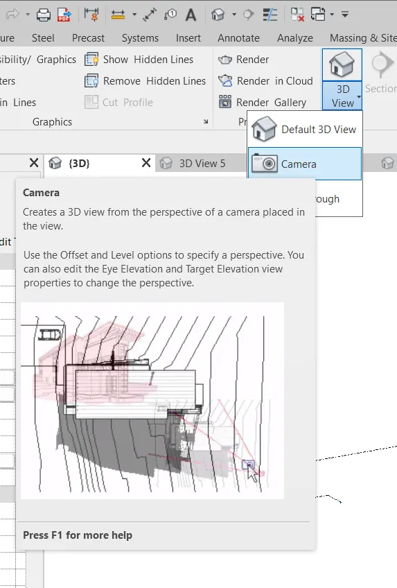
- Click the small arrow near the 3D view, and click the camera button on the drop-down menu. Then you can define the camera by two clicks: the camera position and target position. After you define the camera, Revit will automatically open a new view. This view will show you what your camera sees.
The Perspective option controls whether a 3D view displays as perspective instead of orthographic.
- Open a plan, section, or elevation view.
- Click View tabCreate panel3D View drop-downCamera.
Note: If you clear the Perspective option on the Options Bar, the view that is created is an orthographic 3D view and not a perspective view.
- Click in the drawing area to place the camera.
- Drag the cursor to the desired target and click to place it.
Revit creates a perspective 3D view and assigns a name to the view: 3D View1, 3D View2, and so on. To rename the view, in the Project Browser right-click it, and select Rename.
PROCEDURE :
- Open the new sheet and set the unit
- set the levels
- use the sheet option in views on tool bar
- set new sheet and modify the size
- Here we can also set the name and number of the sheet individually
- Here we have 3 number of different sheet want to create as followed by the given questions
- use the camera option in the view on tool bar
- take the camera and turn the plan into 2d
- place the camera on bed room, kitchen, hall/living room
- Next we taken the A-501 - Bed room elevation sheet and drag the bed room elevation into the sheet and modify the size of the diagram.
- Next we taken the A-502 - Kitchen room elevation sheet and drag the Kitchen room elevation into the sheet and modify the size of the diagram.
- Next we taken the A-503 - living room elevation sheet and drag the living room elevation into the sheet and modify the size of the diagram.
RESULT :