3D Creation of Celing, Roof, Architectural plan, Structural plan, Sectional view, Elevation view and Camera specific view for a house plan using REVIT
1.AIM
To create the model of ceiling above the top of the walls at first floor level.
INTODUCTION
- Ceiling is an overhead interior surface that covers the upper limits of the buildings.
- It is not generally considered a structural element, but a finished surface concealing the underside of the roof structure or the floor.
PROCEDURE
- To Create the Model of First floor level with a standard properties of all elements, as shown below.
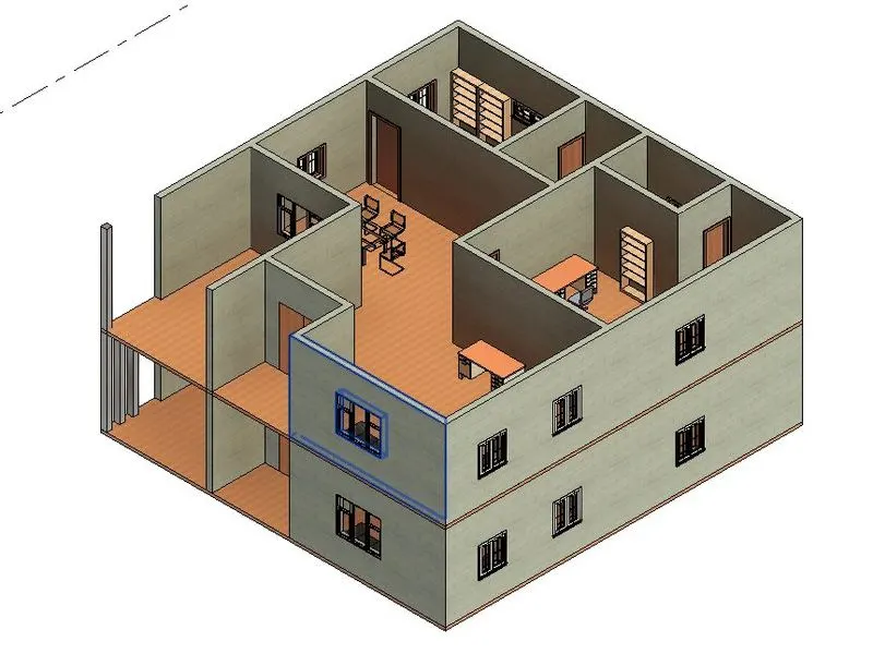
- The height of wall is designed by 10 feet from the base level of First floor.
- And then, adding the all components of categories like family and elements.
- After that, to create a Model of ceiling from Architectural tab, above the wall at first floor level, as shown below.
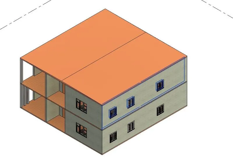
- After creating a ceiling, click the roof and go to edit option could change the dimension and thickness.
RESULTS
Successfully created the ceiling for above the walls at the first floor at the proper standard dimensions.
2.AIM
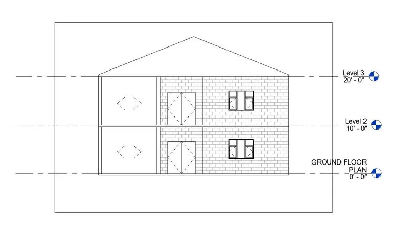
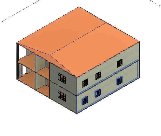
To create a Model of Roof above the ceiling with the slope of 10 degree by using adjustment toolbars.
PROCEDURE
- To create the floor level plan with the ceiling level
- After creating the floor plan, then goes to add the floor above the top of the level.
- To select Architecture Tab, to Click the option of ROOF under Footprints.
- After that the creation of roof footprints, then could be change the slope at 10 Degree bu using the adjustable toolbars, as figures are shown in below.
RESULTS
The Roof footprints with a 10 degree slope are successfully created.
3.AIM
To create a Plan Views for Ground floor level and First floor level including all walls, floors and Components and then it separate to structure and architectural plans.
INTRODUCTION
- Architectural Plans – In the field of architecture an architectural plan is a design and planning of building, and can contain the plans of wall, floor and all components of families and elements in the building.
- Structural Plans- In the field of structural plan that must consider the details of walls, floors and columns.
PEOCEDURE
- To create a plan of Ground floor and first floor as a standard level of residential building.
- Adding the all components of our need of placing the elements in bed rooms, living area, kitchen, storage room, rest room, etc..,
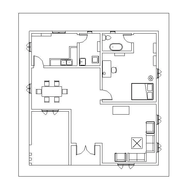
- For architecture plan of Ground floor and First floor model and create a plan view of both and adding the all components in a plan, as shown in below.
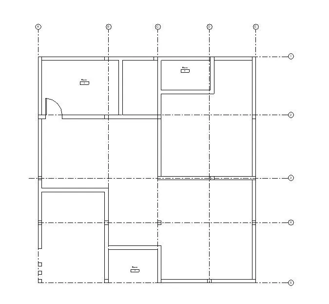
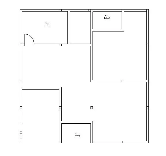
- For structural plan of Ground and First floor model and create a plan view of both and shown the walls, floors and columns.
RESULTS
The architectural and structural plan view of Ground and First floor plan model are successfully created.
4.AIM
To create a Longitudinal and Transverse grids of plan and more to use the annotative toolbar for adding dimensions of all the walls and floors.
PROCEDURE
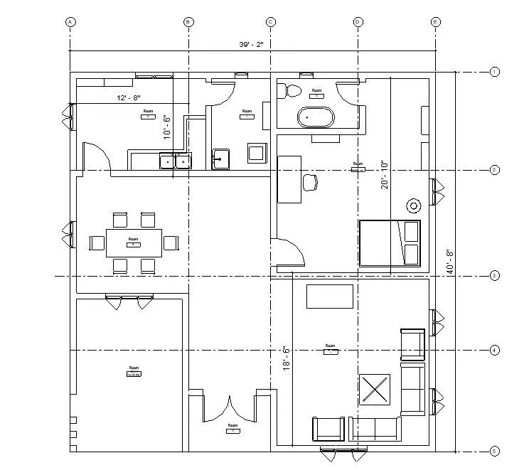
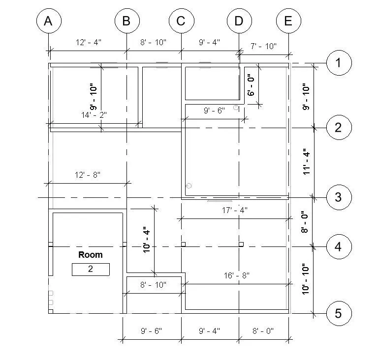
- To add the longitudinal and transverse grids on the floor plan.
- Click the annotation tool bar , then choose to linear dimension for showing the dimension of wall, floor distance.
- For architectural plan dimensions are shown in below.
- The structural plan, by using the annotation tool, to measure the dimension of all walls, floor distance and give the associated grids of longitudinal and transverse by using to mention the all dimensions of wall distance at floor , as shown in below.
RESULTS
The architectural and structural plan has to annotate the dimensions of all elements by using reference of GRIDS is successfully created.
5.AIM
To create a sheet template to add the views of plan
INTRODUCTION
- Sheets are most common purpose of discover the project to client with all data and outlook of project .
PROCEDURE
- To create a sheet template, under view tab to select the sheet, its directly gets in sheet at required files fixtures in our storage.
- Select the sheet model and click ok, automatically the sheets are arrived in screen,
- After that, click the sheet, go to properties for edit the all information and data in a sheet.
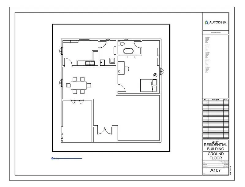
- Then, to add our appropriate view on projects in sheet, as shown below.
RESULTS
The sheet templates with the plan views are successfully created.
6.AIM
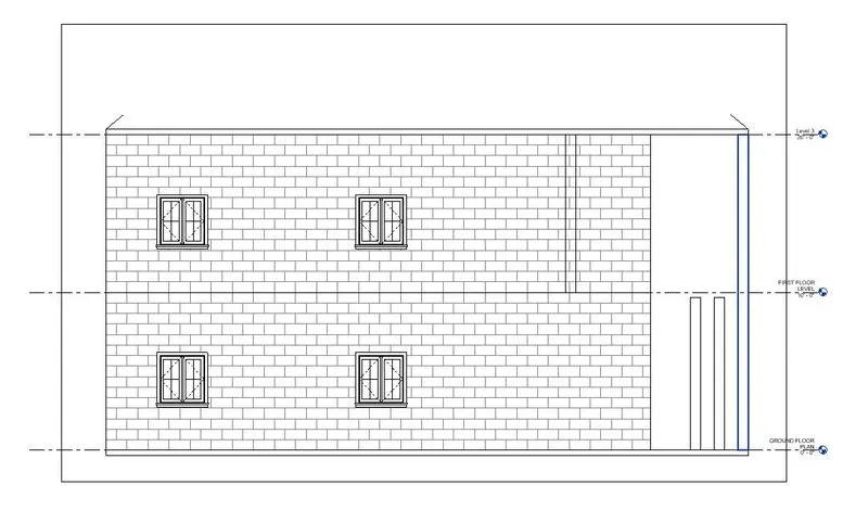
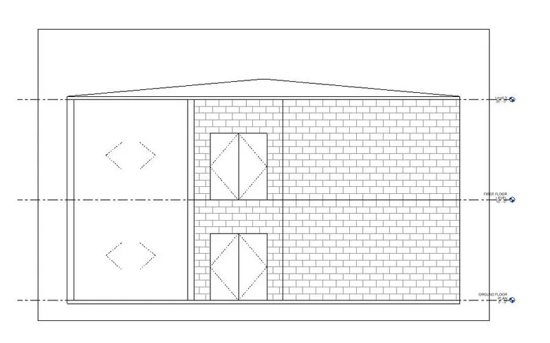
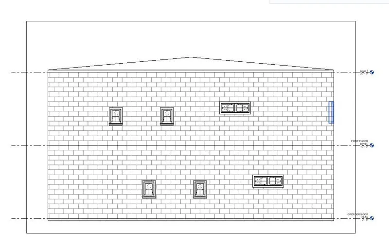
To create a elevation view by using the elevation tab to view the looking of our projects.
INTRODUCTION
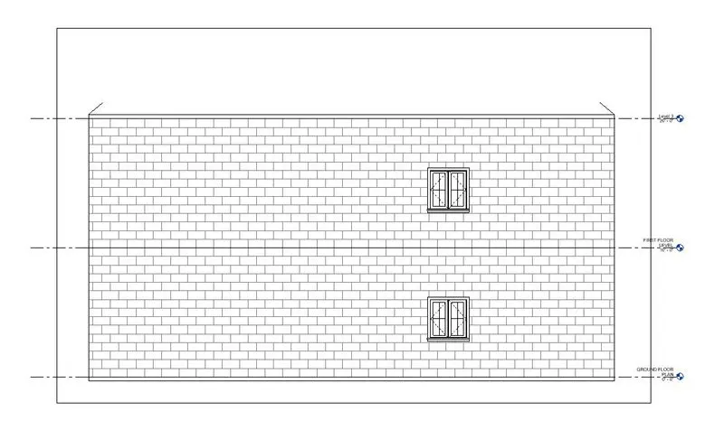
- Generally, the elevation are produced for four directional views, for example north, south, east and west.
- It is in the elevation views where you sketch level Lines. For each level lines that you sketch , a corresponding view is created.
PROCEDURE
- Open a plan view, Click view tab create plan elevation drop down, to choose the region by using the cursor.
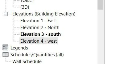
- After that to choose the all direction of elevation view to create it, as shown in figure.
RESULTS
The elevation view of all direction is successfully created.
7.AIM
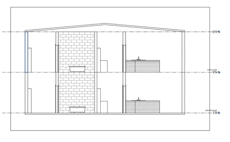
To create a cross sectional view of the plan at each room
INTRODUCTION
- The cross section view , as shown on a drawing, is a depiction of the construction components, from the side of the components.
- Is used to imagine that construction components has been cut across its center.
PROCEDURE
- Open the view tab, to select the section , then to draw the section line along the plan views, have automatically create the sectional views, as shown in below.
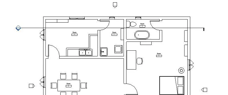
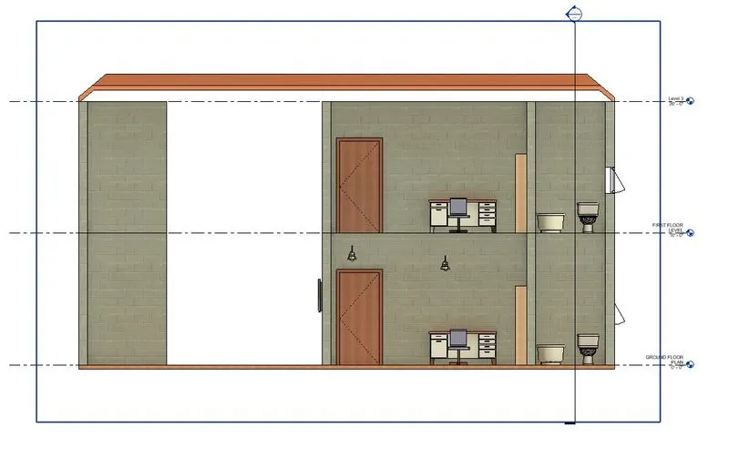
RESULTS
The cross sectional view of plan is successfully created.
8.To classify the views of projects as plan views, section and elevation views.
- Use views to Navigate the model.
- Its contains managing views- organize views, create view lists, and use view types.
- To make multiple copies of a view that are dependent on the primary view.
- The plan views – that are views is the default view when you are start a new project using a structural elements.
- In the new plan dialog, select one or more levels for which you want to create a plan view.
- If you want to create a plan view for a level that has an existing plan view, clear do not duplicate existing views.
- Section view – the main purpose of section view is used to cut the model. Yu can draw them in plan, section, elevation and detail views.
- It represents in intersecting views in our project.
- Elevation view - Generally, the elevation are produced for four directional views, for example north, south, east and west.
- It is in the elevation views where you sketch level Lines. For each level lines that you sketch , a corresponding view is created.
9.AIM
To create the multiple sheet by using the sheet template.
INTRODUCTION
- Sheets are most common purpose of discover the project to client with all data and outlook of project
PROCEDURE
- To create a sheet template, under view tab to select the sheet, its directly gets in sheet at required files fixtures in our storage.
- Select the sheet model and click ok, automatically the sheets are arrived in screen,
- After that, click the sheet, go to properties for edit the all information and data in a sheet.
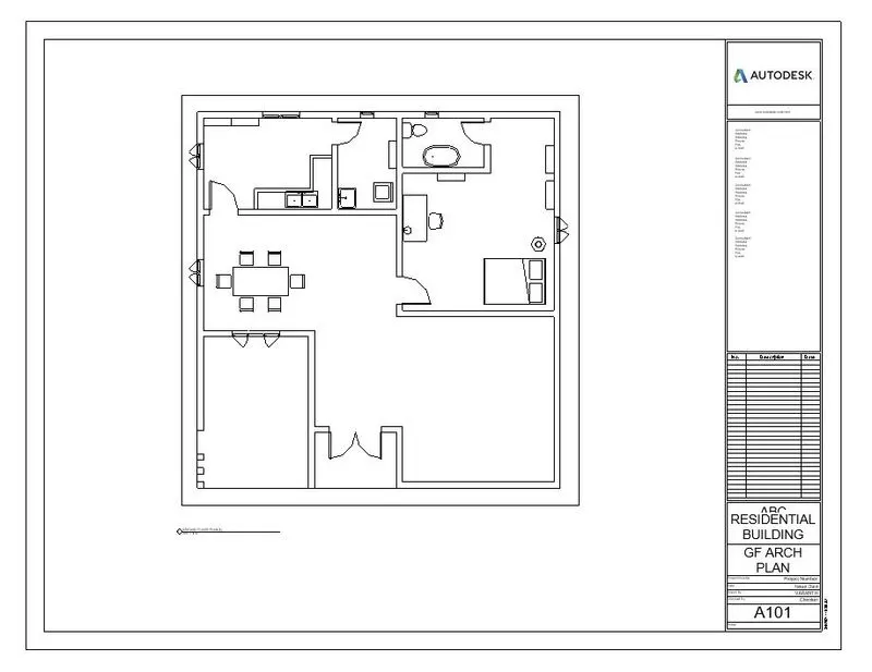
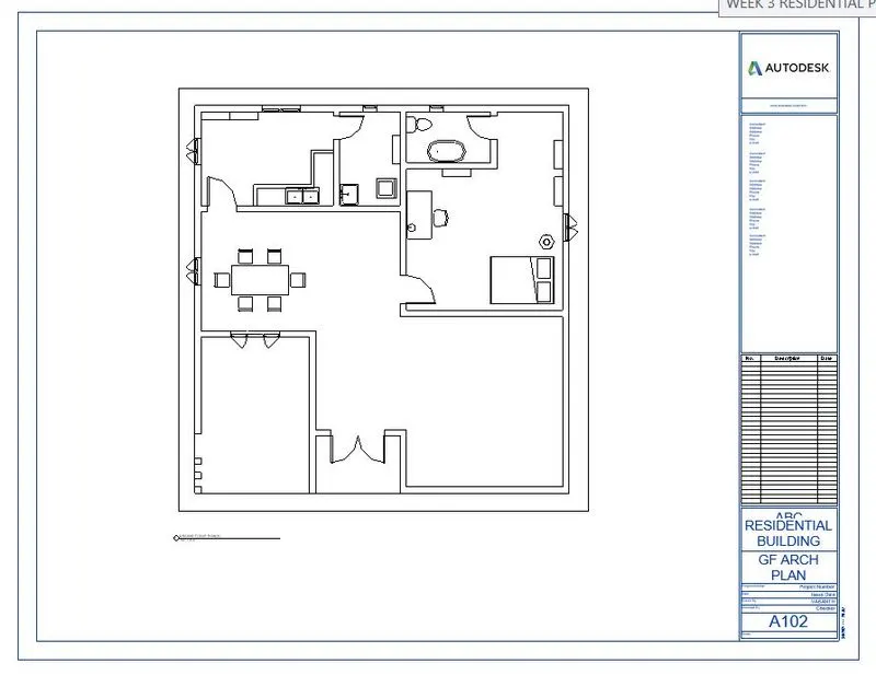
- Then, to add our appropriate view on projects in sheet, as shown below.
- The multiple sheets are created below.
- A101 – Ground Floor Architectural plan, as shown below
- A102 – First Floor Architectural plan, as shown below.
- A103 – Roof Plan, as shown in below.
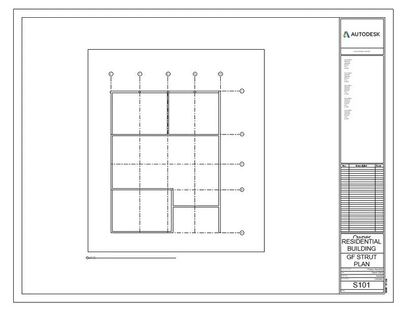
- S101 – Ground floor structural plan , as shown in below.
- S102 – first floor structural plan, as shown in below.
- S103- Roof Farming plan, as shown in fig.
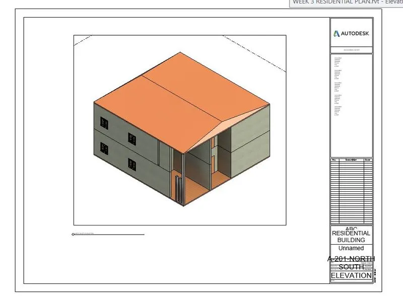
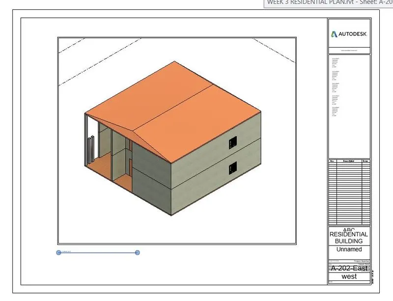
- A-201- North South Elevation.
- A-202- East west elevation.
RESULTS
Successfully created the multiple sheet view of given standards.
10.AIM
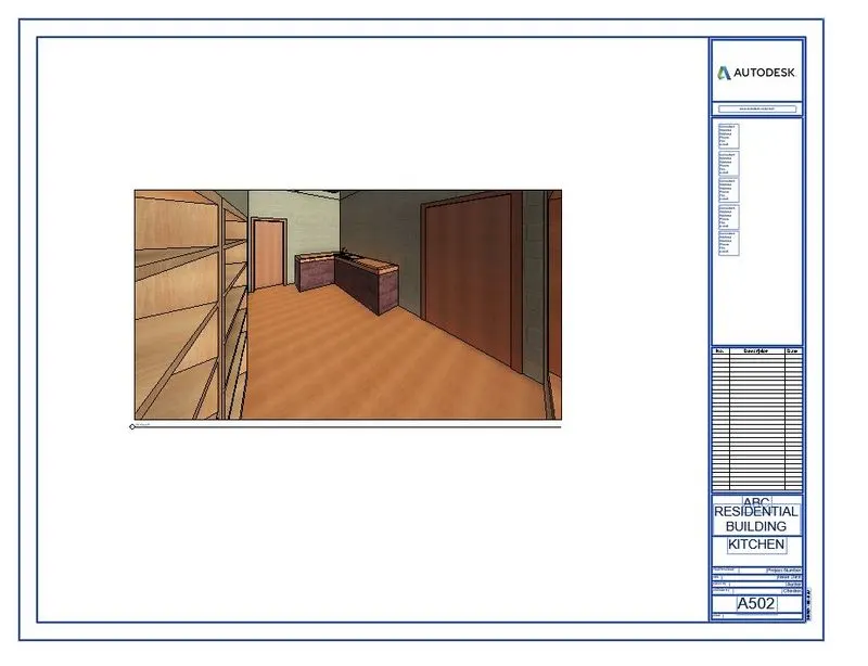
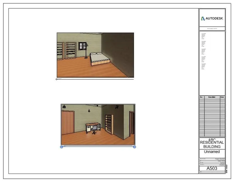
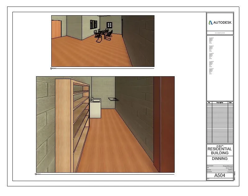
To create a camera specific view or 3D view to add the sheet templates.
PROCEDURE
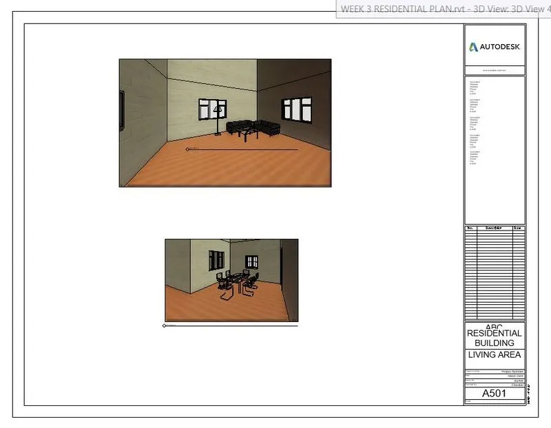
- To fix the camera on plan such as living room, kitchen, dining room, bedroom and then to save the view of project files.
- After that complete the camera views, to create the sheets to ready for the all views to presentation, as shown in below.
RESULTS
The sheet templates in 3D view of all areas in projects are successfully created.