3D Creation of Celing, Roof, Architectural plan, Structural plan, Sectional view, Elevation view and Camera specific view for a house plan using REVIT
1.AIM:
To model a ceiling from the architectural tab above the walls at the first-floor level
INTRODUCTION:
Ceilings help create an enclosure and separation between spaces, they help to control the diffusion of light and sound around a room and help prevent the passage of sound between rooms.
In Revit, The creation of ceiling is a very similar process as we did for floors and roofs
PROCEDURE:
- Open Revit Software and Click on new to open the Architectural Template file
- In the file tab, load the week 3 project that we did earlier
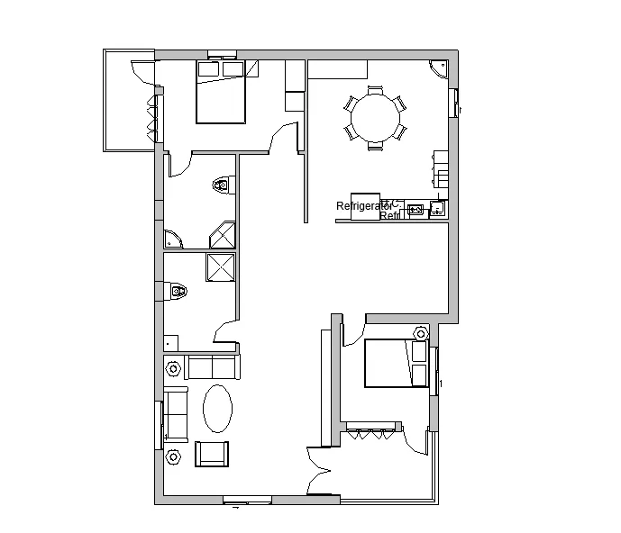
- Now we have to create the ceiling to this first-floor level as given below
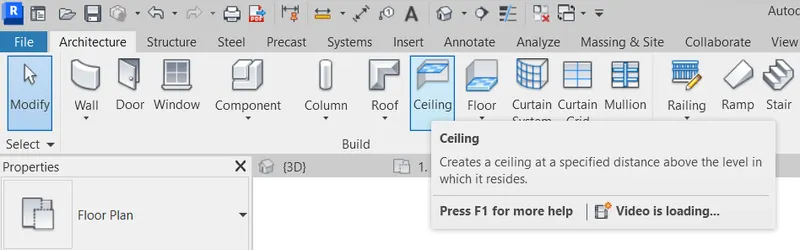
- Go to the Architectural tab and Click on Ceiling
- There are two methods for creating the ceilings (Automatic ceiling and sketch ceiling)
- For this floor plan, we use the sketch ceiling option
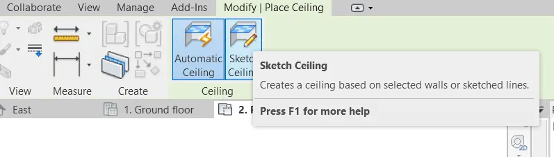
- We select the sketch the ceiling option from the architectural toolbar
- It will open modify tab, select the pick line option
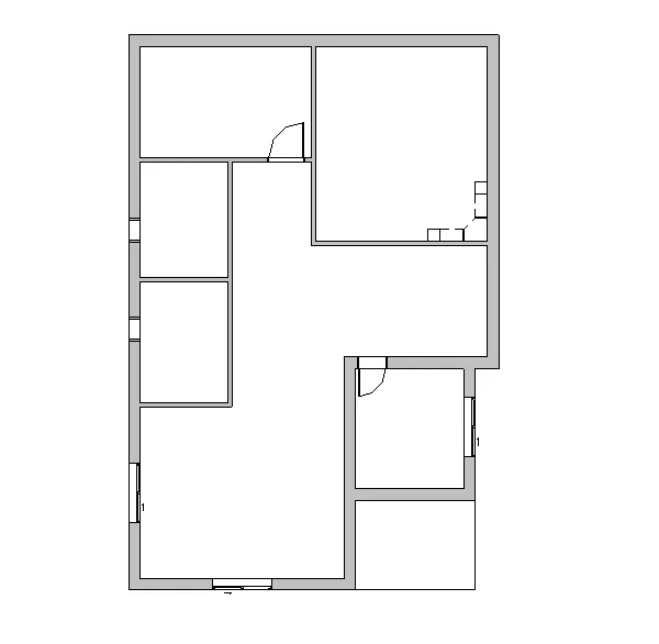
- Pick the exterior lines of the wall carefully as shown in the figure below
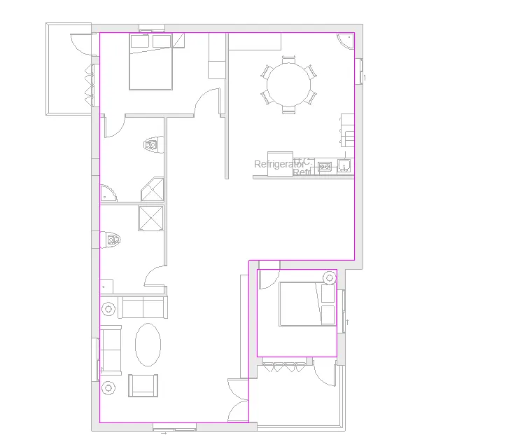
- Click on the green tick mark and press Esc to close
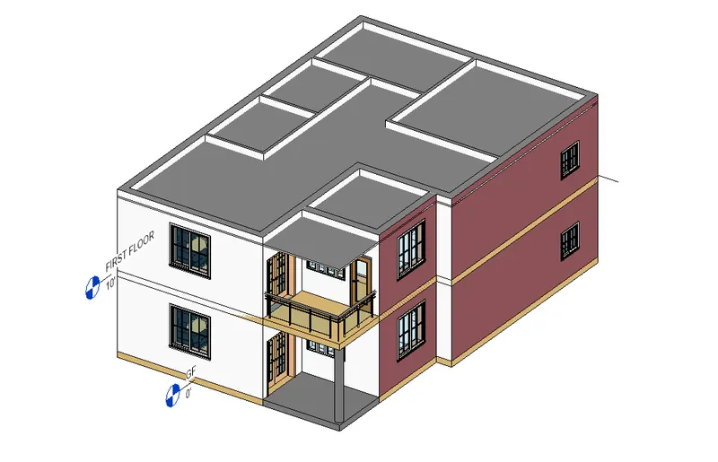
- The ceiling has been created as shown in the figure below
RESULT:
The ceiling for the first-floor level has been created successfully for the residential building.
2.AIM:
To model a Roof above the ceiling by selecting the footprints of the ceiling
INTRODUCTION:
A roof is a top covering of a building, including all materials and constructions necessary to support it on the walls of the building or uprights, protecting against rain, snow, sunlight, extremes of temperature, and wind. A roof is part of the building envelope.
In Revit, there are different methods to design a roof (i.e., Roof by footprint, Roof by Extrusion, Roof by face, etc). It creates a roof using the building footprint to define its boundaries
PROCEDURE:
- Go to the Architectural tab, and select the roof option
- It will display different methods to create the roof
- Select the Roof by footprint option from the architectural toolbar
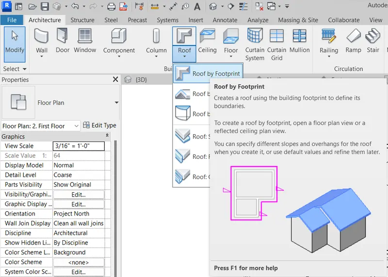
- After Selecting the Roof by footprint option, it will display the modify tool tab
- Select the pick line option and select the exterior lines of the walls as shown in the figure below
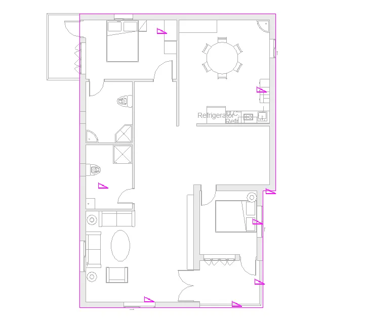
- After Selecting the exterior lines of the walls, Click the green tick option to create the roof
- Now the roof has been created above the ceiling height
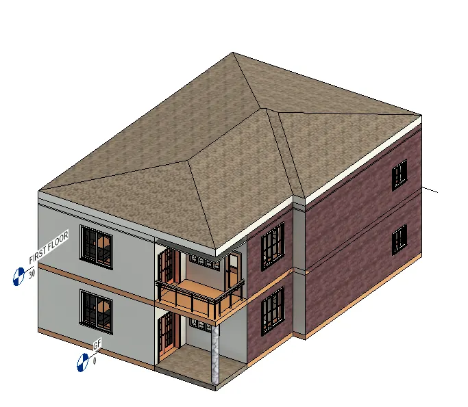
- Now we have to adjust the slope to 10 degrees as per the given requirement
- Type UN and open the Project units dialog box
- Select the slope and change the units to degrees and click Ok
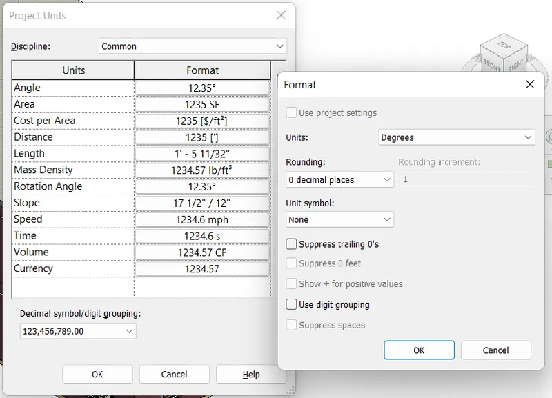
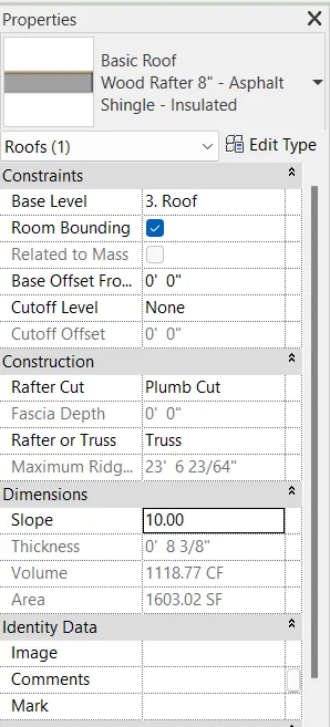
- Select the Roof and go to Properties browser
- Under the dimensions tab, select the slope option and give the slope as 10°
- Click Apply to make changes to the roof
RESULT:
The roof has been created successfully above the ceiling and the slop has been adjusted to 10 degrees.
3.AIM:
To create plan views for ground floor level and first-floor level and separate them into Architectural and Structural plans
INTRODUCTION:
Revit offers different templates for Architectural, Structural, and MEP engineers to work easily based on the preloaded settings in the templates. When we open the Architectural Template, it will consist of both architectural and structural tabs.
The Architectural tab consists of walls, windows, doors, roofs, floors, etc that are used for architectural purposes and modeling whereas the Structural tab consists of structural walls, Columns Beams other Structural elements used for analysis.
PROCEDURE:
- First, we have to draw the architectural plans for the ground floor level and first-floor level
- We have already created a plan that consists of ceiling and roof
- Go to the View tab, and select the Plan views option
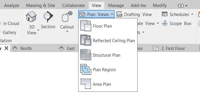
- First we select the Floor plan option and click Ok
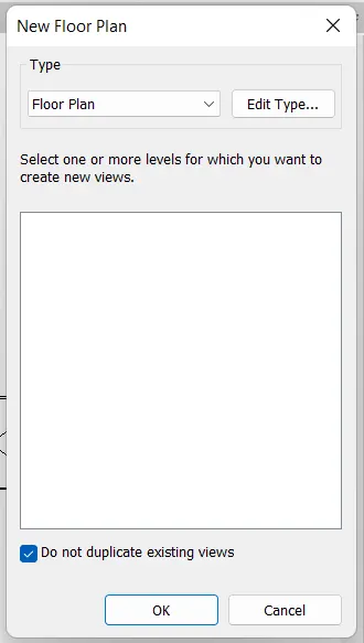
- Now we can see the architectural plans of the ground floor level and first-floor level as shown in the figure below
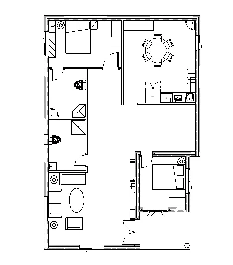
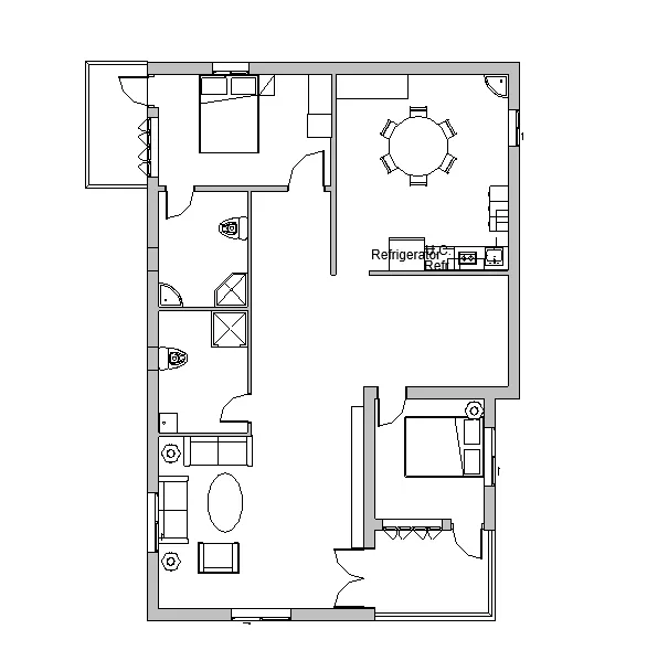
- Now we have to switch the views from architectural to structural view
- Go to the View tab and select the Plan views option
- Select the Structural plan option from the Plan views section
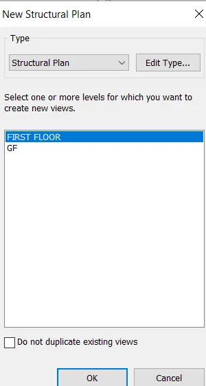
- Select the levels that we want to view the structural plans
- Select the levels as the Ground floor and First floor
- After Selecting the levels, Click ok
- It will show the structural views of all the levels that we selected
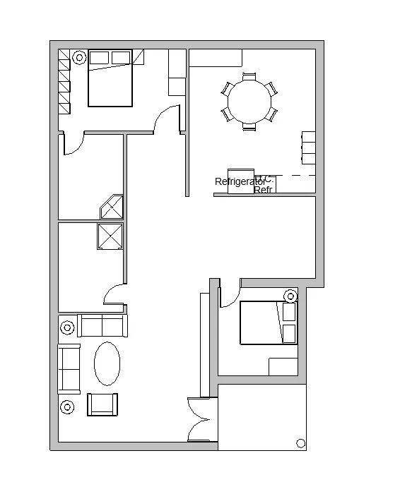
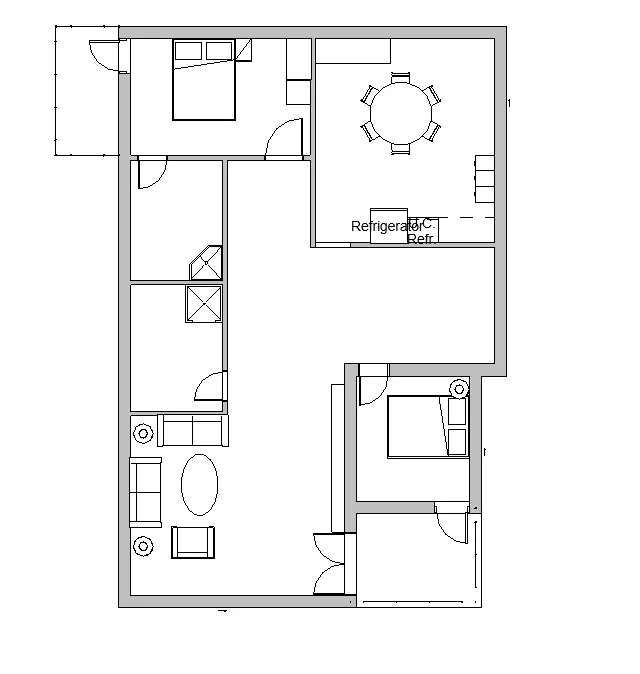
RESULT:
The plan views for both architectural and structural floor plan levels have been created successfully
4.AIM:
To add dimensions to all the walls and floors concerning the longitudinal and transverse grids created in the project file
INTRODUCTION:
The Dimension tool lets you place permanent dimensions on components in your project or family. We can choose from aligned, horizontal, vertical, angular, radial, or arc length permanent dimensions.
PROCEDURE:
- Go to Project browser and select the ground floor plan
- Then go to Annotate tab and select the aligned dimension tool
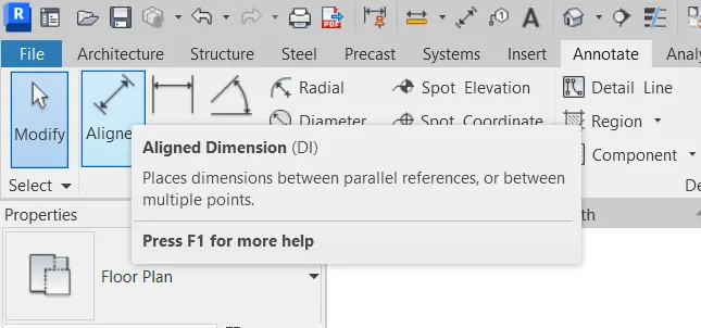
- By using the aligned dimension tool, place the dimensions according to the grids
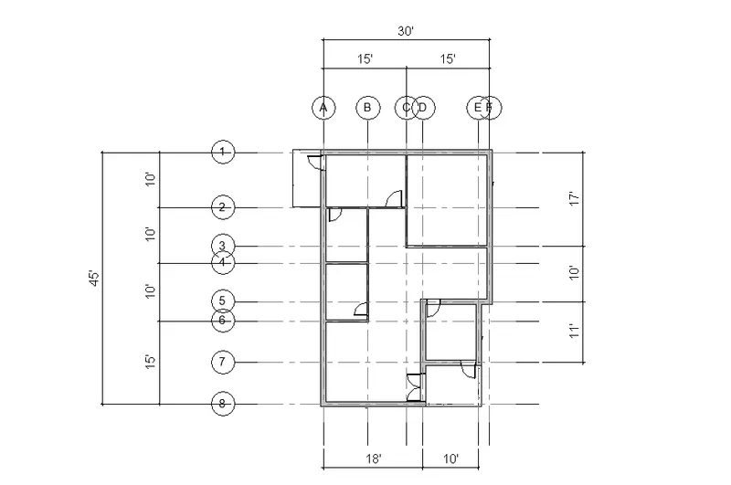
- Create horizontal and transverse dimensions for separate rooms as shown in the figure below
- Similarly add the dimensions to the first-floor plan as well using the aligned dimension tool
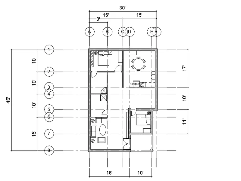
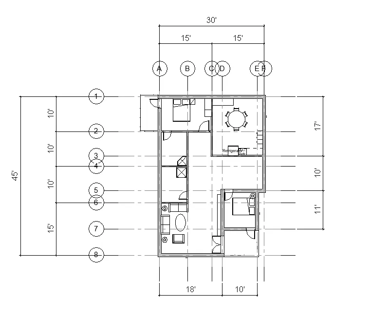
- Now go to Project browser and Expand the Structural views
- Now select the Ground floor level of the structural plan by double-clicking it
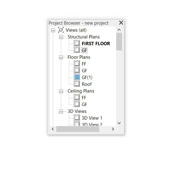
- Select the aligned dimension tool and add the dimensions for the structural ground floor plan
- Place the dimensions horizontally and transversely as shown in the figure below
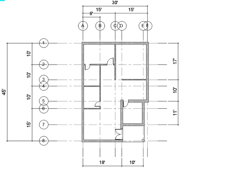
RESULT:
a) The dimensions are successfully added to the Architectural floor plans concerning grids
b) The dimensions are successfully added to the structural floor plans concerning grids
5.AIM:
To create a sheet template from the view tab and adjust the parameters on the sheet to add appropriate views
INTRODUCTION:
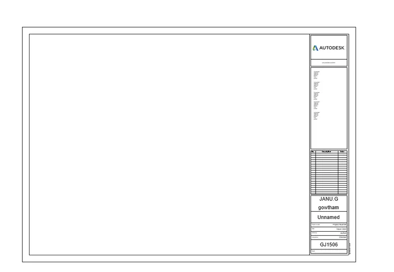
A construction document set (also called a drawing set or a sheet set) consists of several sheets.
In Revit, we create a sheet view for each sheet in the construction document set. We can then place multiple drawings or schedules on each sheet view.
PROCEDURE:
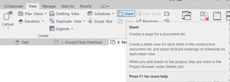
- First we have to select the sheet option from the view toolbar
- Go to the View tab and select the sheet option
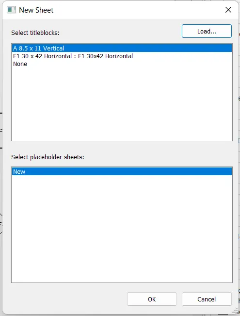
- After clicking the sheet option, a New sheet dialog box will open
- Load the sheets from the Libraries (Libraries > US > Title blocks)
- Load the required sheet as per the requirement
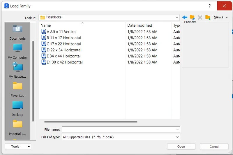
- After loading the sheets into the Revit Model, select the sheet that we want to open
- We selected the Sheet file as A 8.5 x 11 vertical
- After Selecting the sheet, it will appear on the screen
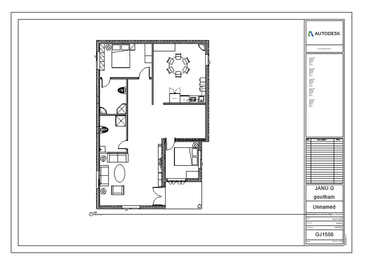
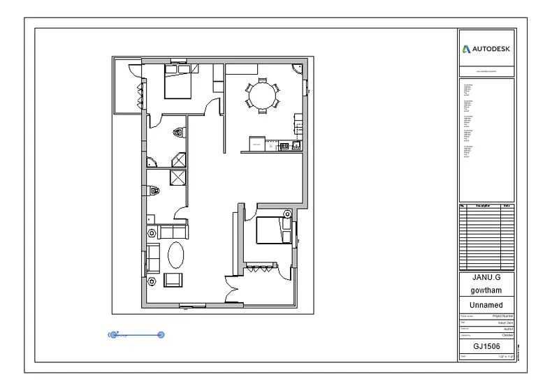
- In the sheet template, we insert the ground floor and first-floor plan separately
RESULT:
The Sheet template from the view tab has been successfully created with appropriate views
6.AIM:
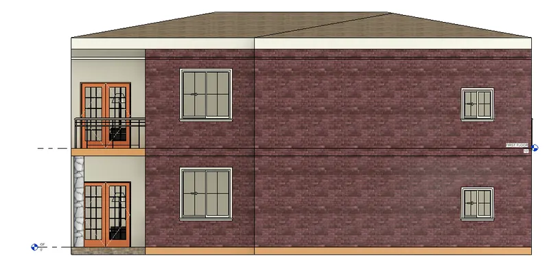
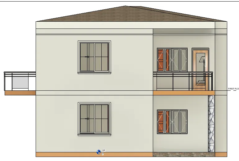
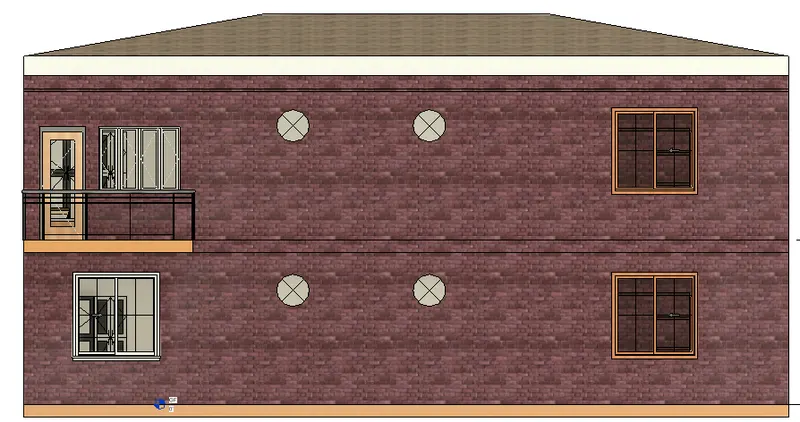
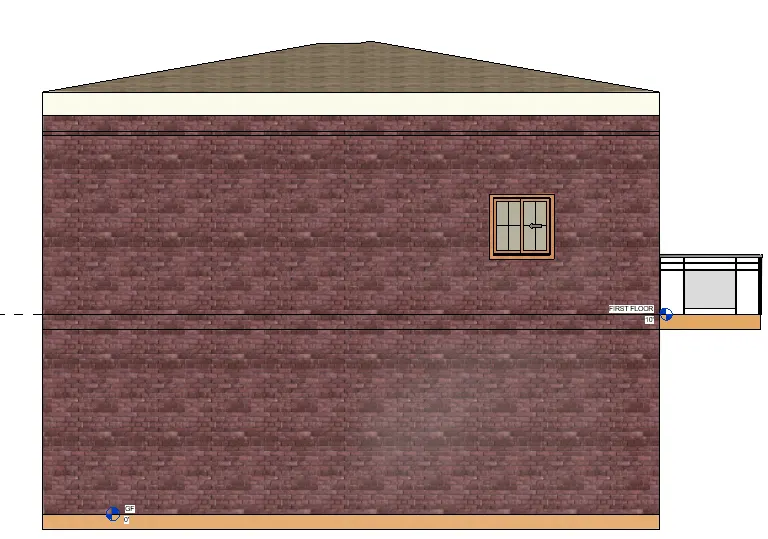
To create the elevation views such as North, South, East, and West using the elevation tab
INTRODUCTION:
Elevation views are part of the default template in Revit Architecture. When you create a project with the default template, 4 elevation views are included: north, south, east, and west. It is in elevation views where you sketch level lines. For each level line that you sketch, a corresponding plan view is created.
We create additional exterior elevation views and interior elevation views to look at a project from different locations
PROCEDURE:
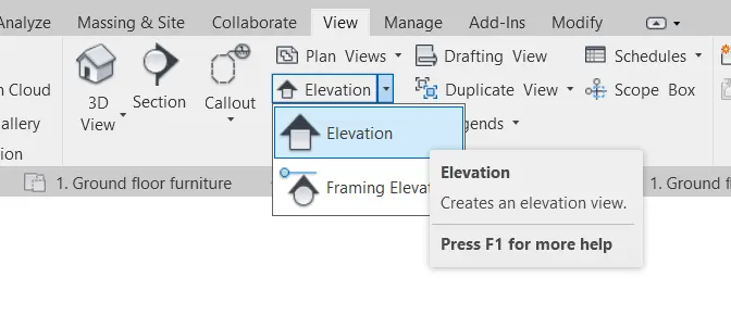
- Go to the View tab and select the elevation option
- By default it shows two options i.e., Elevation and Framing Elevation
- We select Create elevation view
- After Selecting the Create Elevation, place the elevation tags at the required positions
- We are placing at East and North as shown in the figure below
- After placing the elevation tags, we can now see the different locations of views
East:
South:
West:
North:
RESULT:
All the Elevation views have been created and placed successfully at different locations
7.AIM:
To Produce a Section cut through each room either cutting across longitudinally or in a transverse direction
INTRODUCTION:
Section views display as section representations in intersecting views. Sections views cut through the model. You can draw them in the plan, section, elevation, and detail views.
We can create building, wall, and detail section views. Each type has a unique graphical display, and each is listed in a different location in the Project Browser.
PROCEDURE:
- Go to the View tab and select the Section option
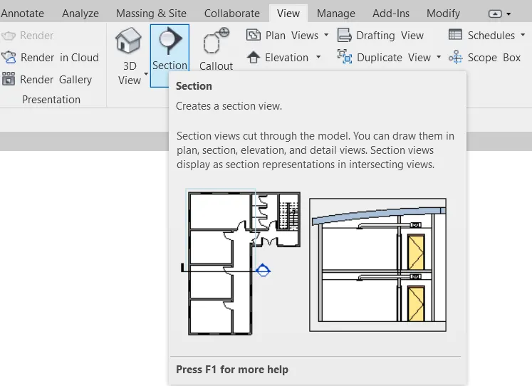
- After Selecting the Section tool, place the first point and the second point in between the section view
- The section views have been created as shown in the figure below
- Similarly using section tools, cut the sections for all the rooms
- After creating the section views, now we can see the sectional tags on the floor plan
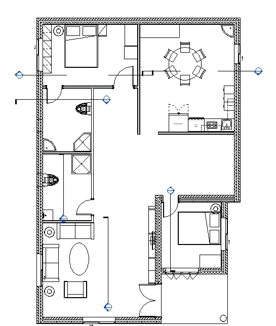
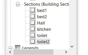
- After creating the section views, go to Project browser
- Expand the section views and change the names of the views as shown in the figure below
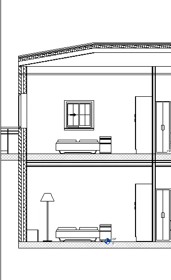
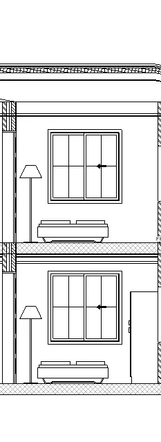
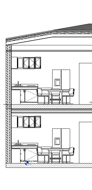
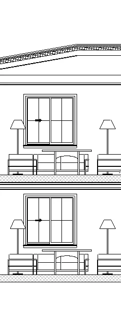
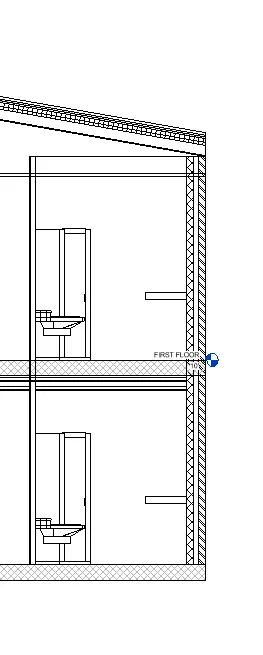
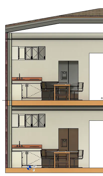
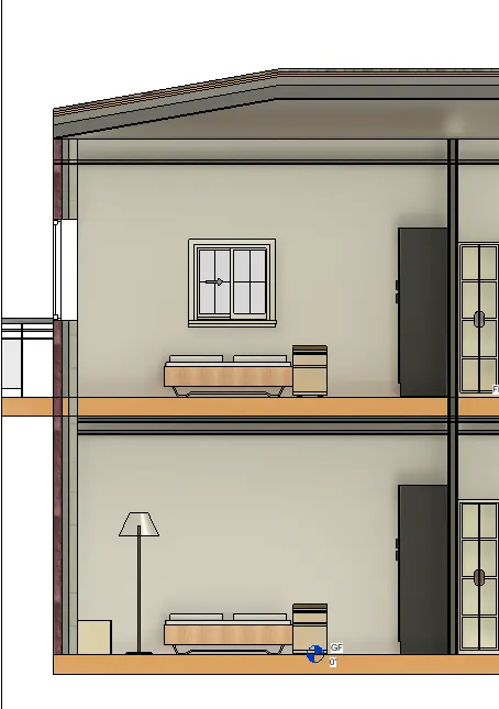
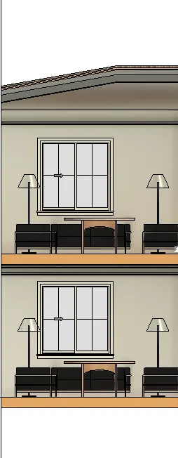
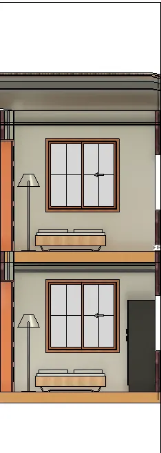
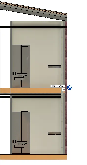
- The Sections for different rooms have been created and produced as shown in the figures below
Bedroom 1:
Bedroom 2:
Kitchen:
Living room:
Restroom:
RESULT:
All the section views of each room have been created successfully
8.AIM:
To classify the different views to either design or documentation category using the Properties browser
INTRODUCTION:
Revit provides standard view types for 2D views and 3D views, such as floor plans, elevations, and sections. If desired, you can duplicate a view type and customize it to use certain settings or a particular view template. Custom view types allow you to apply consistent settings to new views quickly and easily.
A view type defines some graphics properties, such as a reference label and tags for elevations, callouts, or sections. It can also specify a view template to apply to a new view, and whether template updates should be applied to existing views.
PROCEDURE:
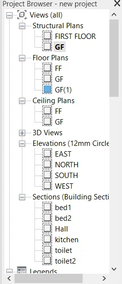
- First we open the project browser, where we can see all the views and plans
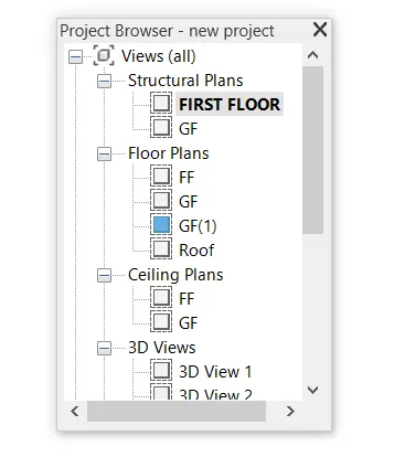
- The different types of views that are categorized as Structural plans, Floor plans, Ceiling plans, 3D views, Elevations, and sheets
- Now we access all the plans and views one by one
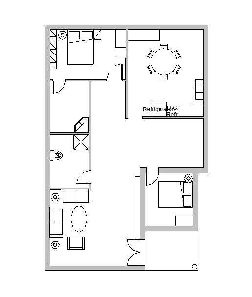
- To see the ground floor plan, go to Project browser expand the floor plan, and select the Ground floor plan
- Next, we see the first-floor plan under the project browser
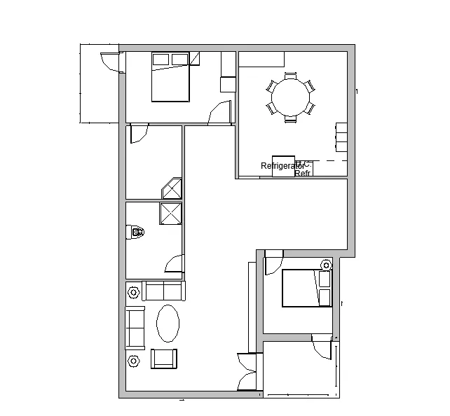
- To see the first-floor plan, go to Project browser expand the floor plan, and select the First-floor plan
- Similarly we can access all the different types of views of structural plans from the project browser
Ground Floor Plan:
First Floor Plan:
- Now, we see the different elevation views from the project browser
East:
South:
West:
North:
RESULT:
All the views have been classified into different types using the project browser
9.AIM:
To create the multiple sheets and produce the drawings in the sheets from the given drawing list
INTRODUCTION:
When creating a project template, we can include sheets in the template. Start with a blank project file, and create the standard views and levels that each project should include. Leave the views empty, but assign standard names to them.
To create a standard set of construction documents, create sheets using the desired title blocks. Add views to the sheets, using the desired viewport templates and view title types. Then save the empty project as a project template.
When we create a project using this project template, all of the views and sheets are already created and listed in the Project Browser. As we start to draw the building model in the project views, the views on the sheets update automatically.
PROCEDURE:
- First we have to select the sheet option from the view toolbar
- Go to the View tab and select the sheet option
- After clicking the sheet option, a New sheet dialog box will open
- We selected the Sheet file as A 8.5 x 11 vertical
- After Selecting the sheet file, Rename the sheet and other project information
- Now we have to produce all the drawings into the sheet
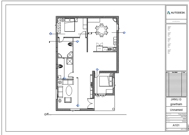
- First we produce the Ground floor Architectural plan in the sheet template as A101 as shown in the figure below
- Go to Project browser, select the Architectural ground floor plan and drag it into the sheet template
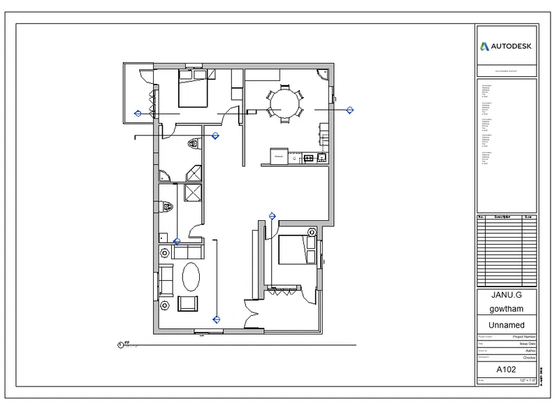
- Next we produce the First-floor Architectural plan in the sheet template as A102 as shown in the figure below
- Go to Project browser, select the Architectural First floor plan and drag it into the sheet template
- Similarly now we have to produce structural plans for the sheet template
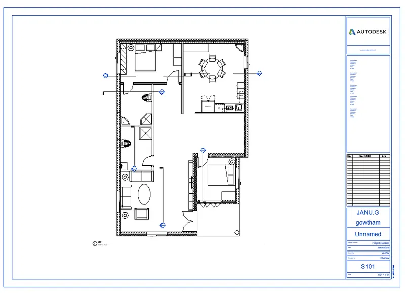
- First we produce the Ground floor Structural plan in the sheet template as S101 as shown in the figure below
- Go to Project browser, select the Structural ground floor plan and drag it into the sheet template
- Next we produce the First-floor Structural plan in the sheet template as S102 as shown in the figure below
- Go to Project browser, select the Structural First floor plan and drag it into the sheet template
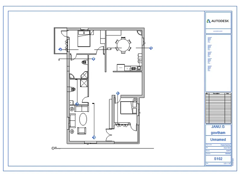
- Now we have to insert South-North Elevation and East-west elevation into the sheet template
- First we produce the South-North Elevation in the sheet template as A201 as shown in the figure below
- Go to Project browser, select the south elevation and North elevation and drag it into the sheet template
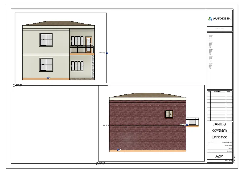
- Next we produce the East-west Elevation in the sheet template as A202 as shown in the figure below
- Go to Project browser, select the East elevation and West elevation and drag it into the sheet template
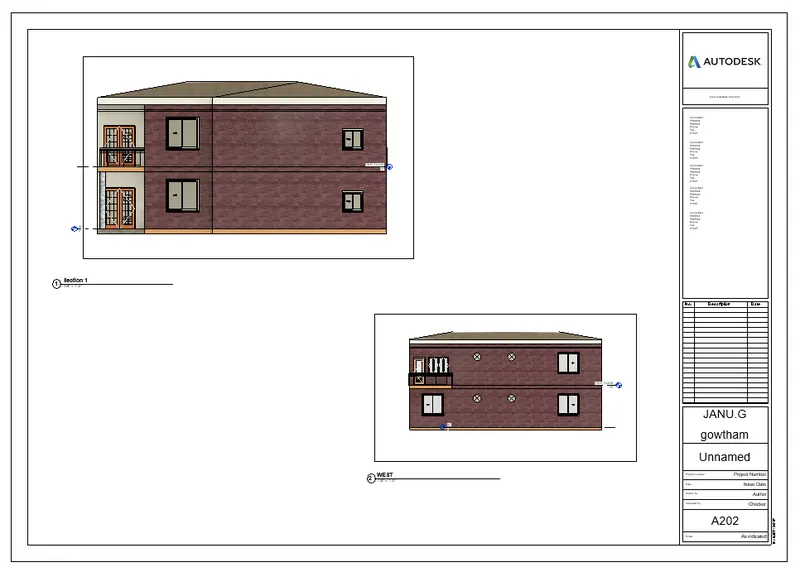
RESULT:
Thus multiple sheets have been created and the drawings are produced into the sheet template as per the requirement
10.AIM:
To create a camera-specific view or a 3D view in each room and Produce into the sheet template
INTRODUCTION:
After creating the 3D model, we can place a camera by activating it from your ribbon, View tab, or Create panel. Click the small arrow near the 3D view, and click the camera button on the drop-down menu
After you define the camera, Revit will automatically open a new view. This view will show you what your camera sees. Mostly we need to modify the view. Make sure modify is active, click the view boundary. You will see the blue grips on the rectangle sides. You can resize the boundary by dragging the grip
PROCEDURE:
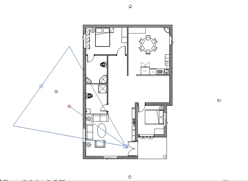
- First we have to set the camera view in the floor plan as per the requirement
- Go to the View tab and open the 3D view option
- Under the 3D view option, Select the camera option
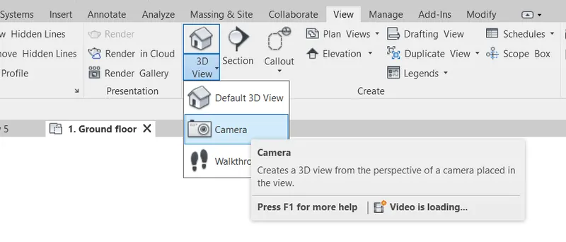
- After Selecting the camera option, now place the camera icon on the floor plan
- After Placing the Icon, now drag the visibility lines for the adjustment as shown in the figure below
- Now we have to produce each room of camera views into the sheet template
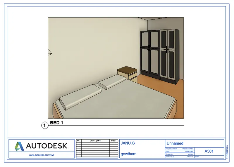
- First we select the sheet and name it A-501
- Now go to the 3D views, Select the bedroom view and drag it into the sheet template
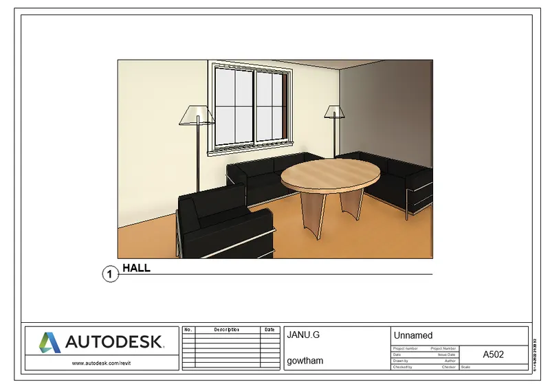
- Now go to the 3D views, Select the Living room view and drag it into the sheet template
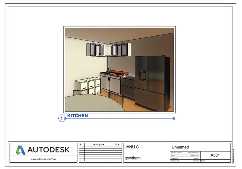
- Now go to the 3D views, Select the Kitchen room view and drag it into the sheet template
- Now go to the 3D views, Select the Restroom view and drag it into the sheet template
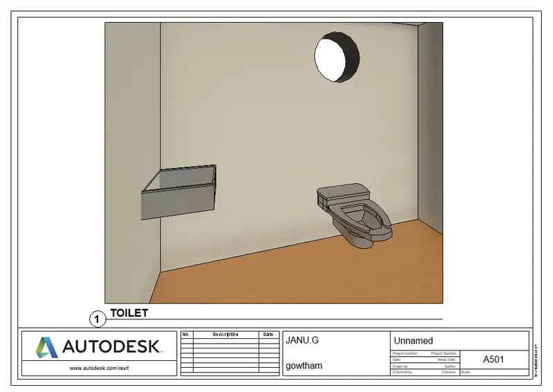
RESULT: