3D Creation of Celing, Roof, Architectural plan, Structural plan, Sectional view, Elevation view and Camera specific view for a house plan using REVIT
1.AIM
To Model a Ceiling from the architecture tab above the walls at the first-floor level
INTRODUCTION
- A ceiling ia an overhead interior surfacew that covers the upper limits of a room
- It is not generally considered a structural element , but a finished surface concealing the underside of the roof structure or the floor of a story above
- Two kinds of ceilings can be placed in model, basic ceilings and compound ceilings
PROCEDURE
STEP1
- Open revit software
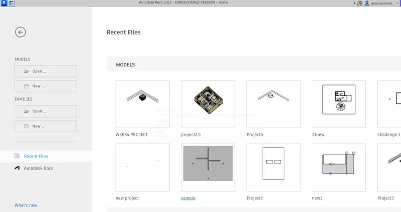
- from the recent files select WEEK 4 PROJECT
STEP2
- Go to the architectural tool bar and select the ceiling option
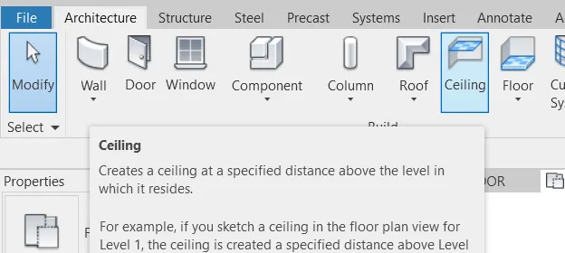
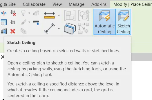
- After selecting the ceiling two options will be available automatic ceiling and sketch ceiling from that select sketch celing
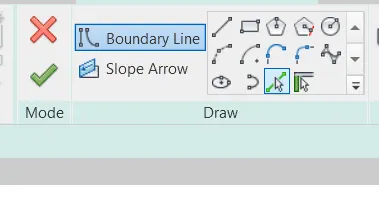
- using pick line option select the line and press the green tickmark
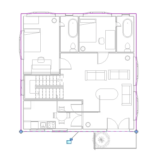
- Then the ceiling will be created as shown in the figure
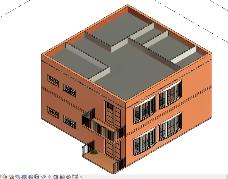
RESULT
Ceiling has been placed over the firstfloor
--------------------------------------------------------------------------------------------------------------------------------------------
2.AIM
To Model a roof above the ceiling
INTRODUCTION
- A roof is the top covering of a building , including all materials and constructions necessary to support it on the walls of the building or on uprights , providing protection against rain, snow , sunlight, extremes of temperature and wind
- A roof is part of the building envelope
PROCEDURE
STEP1
- Open revit software
- from the recent files select WEEK 4 PROJECT
STEP2
- Go to the architectural tool bar and select the roof from that select roof by footprint
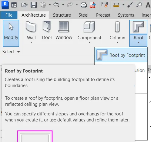
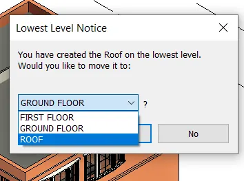
- Select the required area of the roof and select the roof level
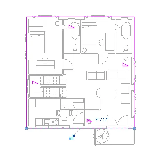
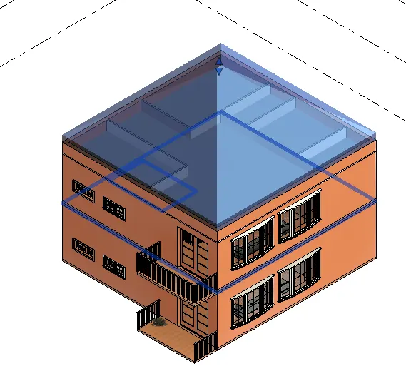
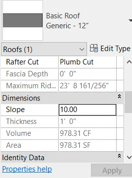
- Change the slope of the roof to 10 degree
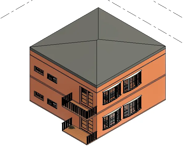
RESULT
The base level is set to roof level and the roof is created
---------------------------------------------------------------------------------------------------------------------------------------------
3.AIM
To create plan views for ground floor level and first-floor level including all the walls, floors, and components.
And to Separate them to architecture and structural plans.
INTRODUCTION
- In the field of architecture, an architectural plan is a design and planning for a building and can contain architectural drawings, specifications of the design , calculations , time planning of the building process and other documentation
- A structure plan is a framework to guide the development or redevelopment of an area by defining the future development and land use patterns , areas of open space , the layout and nature of infrastructure and other key features and constraints that influence how the effects of development are to be managed
PROCEDURE
STEP1
- Open revit software
- from the recent files select WEEK 4 PROJECT
STEP2
CREATING ARCHITECTURAL PLAN
- First we need to go to the property browser and open the floor plans
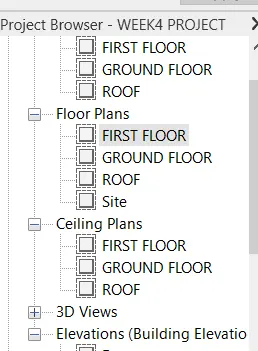
- Click on the ground floor to open the 2D layout
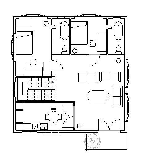
- sameway click on the firstfloor inorder to get the 2D layout of first floor plan
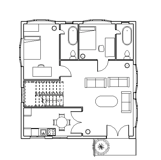
- Architectural plan consist of walls , stairs , windows and doors
- Components are placed in kitchen , living room , bedroom and toilet
- GROUND FLOOR PLAN
- FIRST FLOOR PLAN
STEP3
CREATING STRUCTURAL PLANS
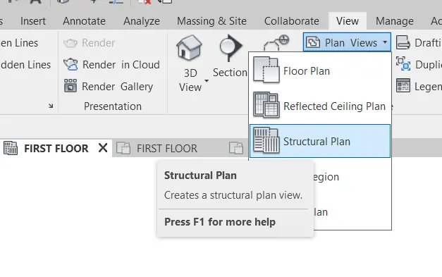
- Go to view tab from that select plan view
- And from that select structural plan
- click on a column to add structural columns to the layout
- concrete rectangular column is added from load family
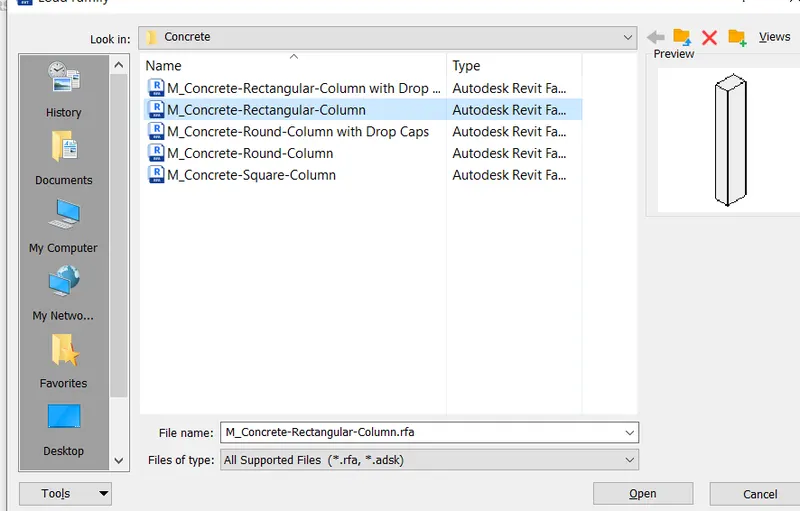
- click open
- place the component where ever it is necessary
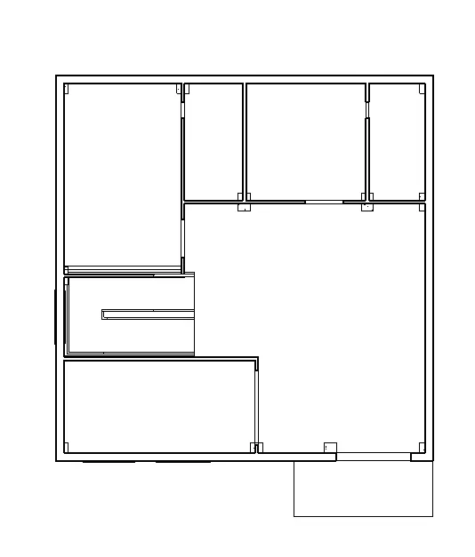
RESULT
Architectural and structural plans are created
-----------------------------------------------------------------------------------------------------------------------------------------
4.AIM
To annotate the project concerning the grids created
INTRODUCTION
- Grids and levels are really the skeleton of building projects
- Typically levels in revit are used to indicate the locations of floors , foundations and the roof of a building in section and elevation views
- Grids are used to host columns and walls
- Grids can be straightlines , arcs or multi segmented.You can hide grid lines after you add them
PROCEDURE
STEP1
- Open revit software
- from the recent files select WEEK 4 PROJECT
STEP2
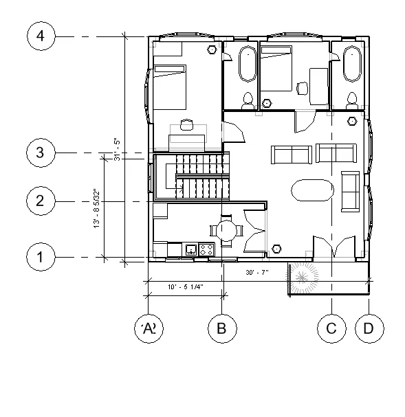
- Draw the longitudinal and transverse grids to the architectural floor plan
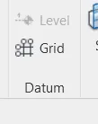
- And add the dimensions to the architectural plan
- By using annotatetab linear dimension
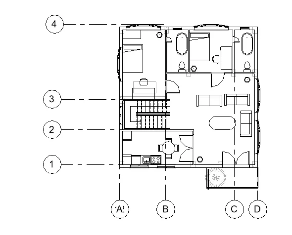
STEP3
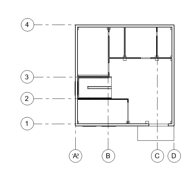
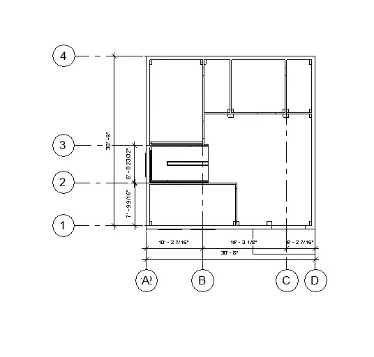
- Draw the longitudinal and transverse grids to the structural floor plan
- And add the dimensions to the structural plan
- By using annotatetab linear dimension
RESULT
-------------------------------------------------------------------------------------------------------------------------------------------
5.AIM
To Create a sheet template from the view tab and adjust the parameters on the sheet to add appropriate views
INTRODUCTION
- A sheet view in revit is a layout where you can place : A title block , multiple drawings, multiple schedules
- In revit using sheet template we can create sheet view of construction document
- We can place multiple drawings or schedules on each sheet view
PROCEDURE
STEP1
- Open revit software
- from the recent files select WEEK 4 PROJECT
STEP2
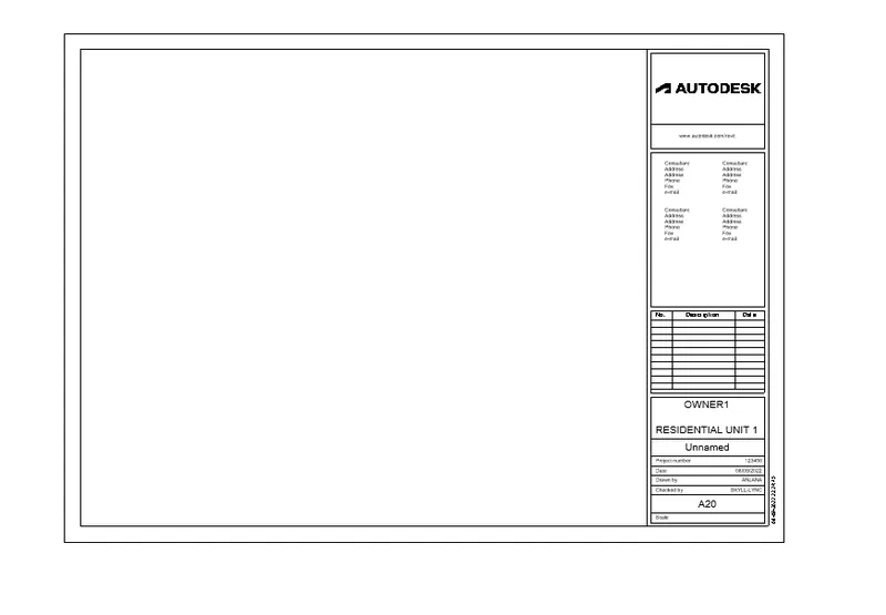
- Click on the sheet option in the viewtab
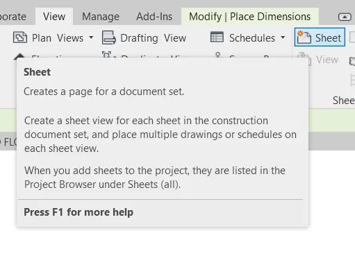
- After clicking the sheet option the new sheet tab will be visible in the screen
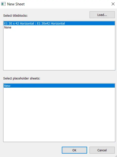
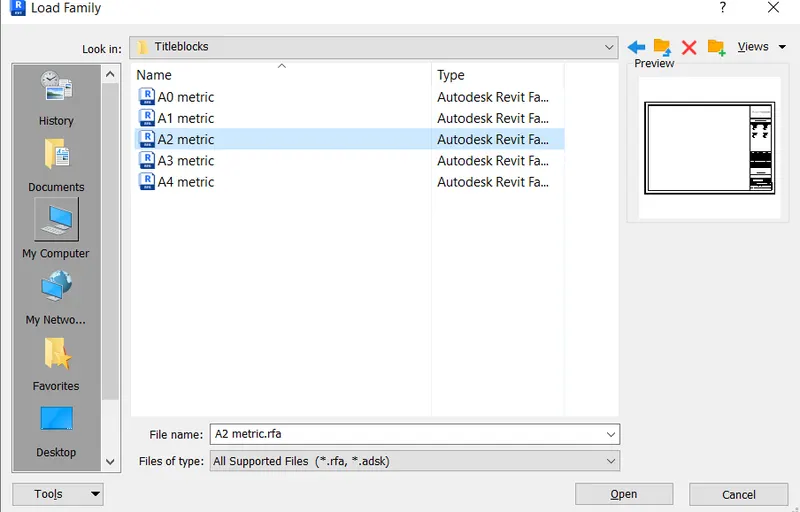
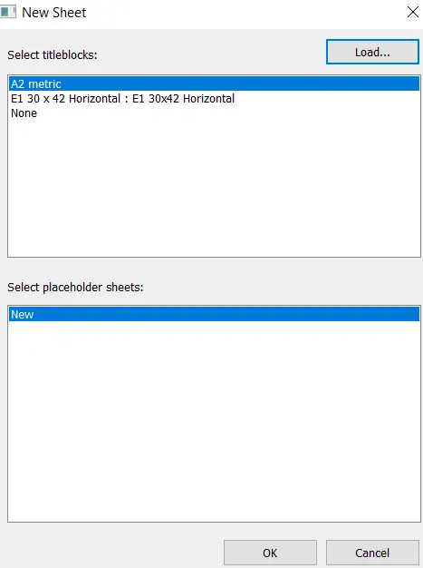
- then load the sheet as per the requirement
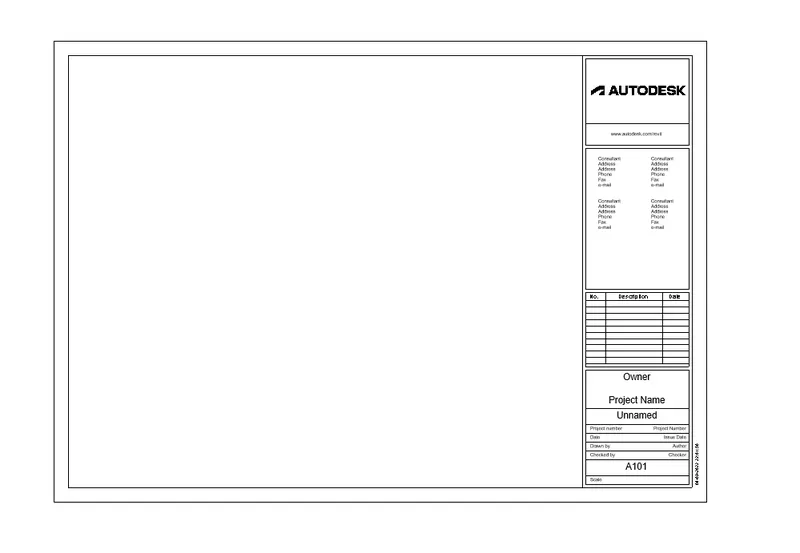
- select the loaded sheet and sheet will be displayed
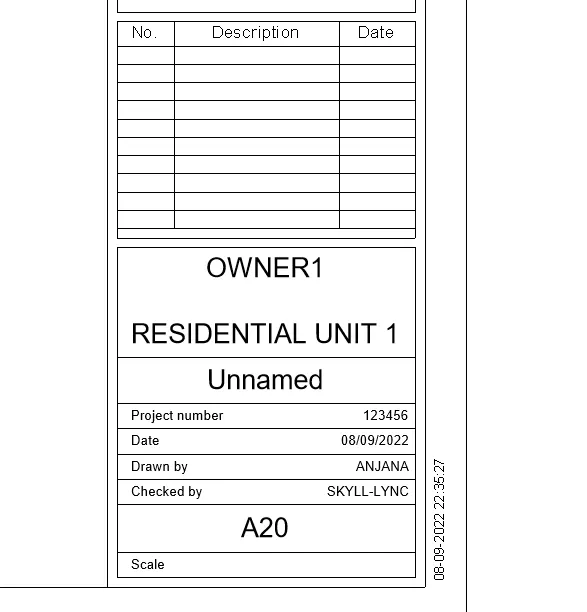
- Edit and change the data in the sheet as per requirement
STEP3
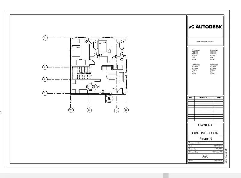
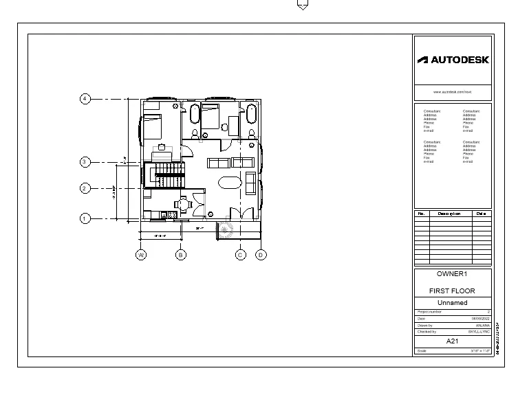
- In the sheet template insert first floor plan and ground floor plan separately
- then edit the project name and sheet number
RESULT
sheet template from the view tab is created and adjusted the parameters on the sheet to add appropriate views
---------------------------------------------------------------------------------------------------------------------------------------------
6.AIM
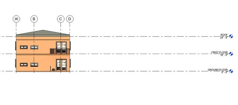
To create the elevation views, looking at your building from East, North, South, and West
INTRODUCTION
- The elevation view can be described as a look at the structure from the side
- Most of the time the elevation views are going to be found exclusively in the architectural drawings
- Each elevation is labelled in relation to the compass direction it faces
PROCEDURE
STEP1
- Open revit software
- from the recent files select WEEK 4 PROJECT
STEP2
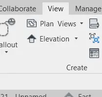
- Click on the elevation option from the viewtoolbar
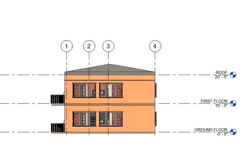
STEP3
- Elevation from the east
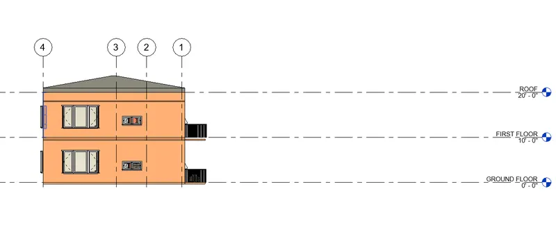
STEP4
- Elevation from the west
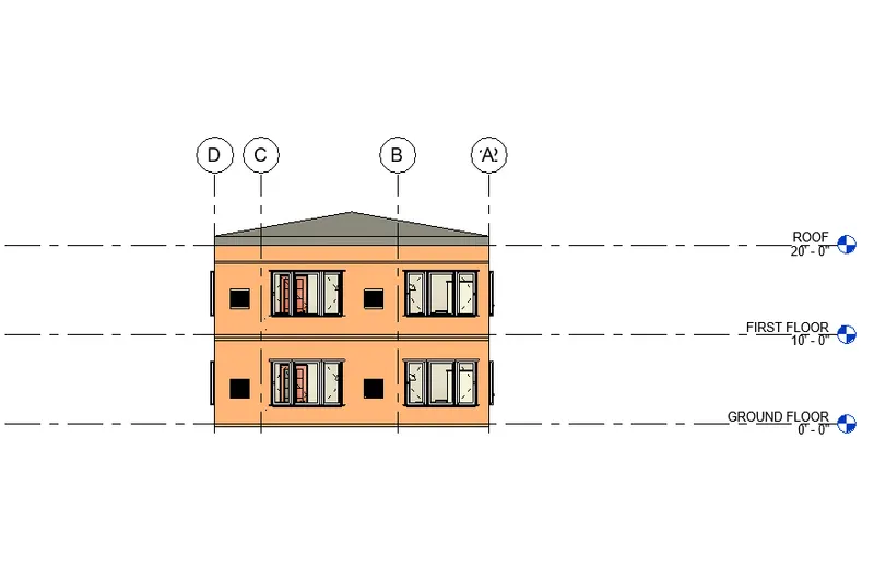
STEP5
- Elevation from the north
STEP6
- Elevation from the south
RESULT
created the elevation views, looking at building from East, North, South, and West
-----------------------------------------------------------------------------------------------------------------------------------------
7.AIM
To Produce section cut through each room either cutting across longitudinally or in a transverse direction
INTRODUCTION
- Sectional views are used in engineering and architectural drawings
- Sectional views reveal the hidden details in a mechanical drawing
- These views assume that a cutting plane has removed portions of the object represented by drawing , displaying the appropriate section of the interior
PROCEDURE
STEP1
- Open revit software
- from the recent files select WEEK 4 PROJECT
STEP2
- Select section option from viewtoolbar
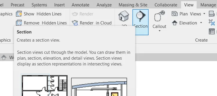
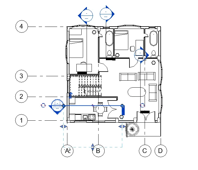
- Cut the sections in the plan
STEP3
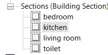
- Section view of bedroom
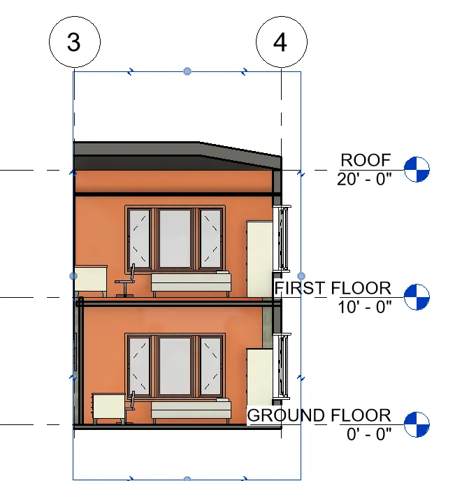
STEP4
- Section view of toilet
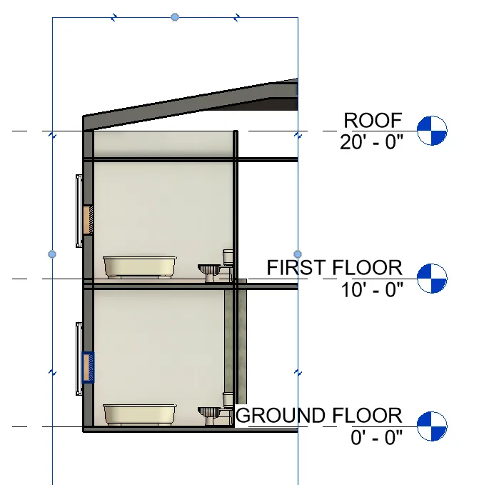
STEP5
- Section view of livingroom
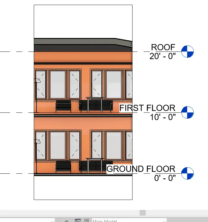
STEP6
- Section view of kitchen
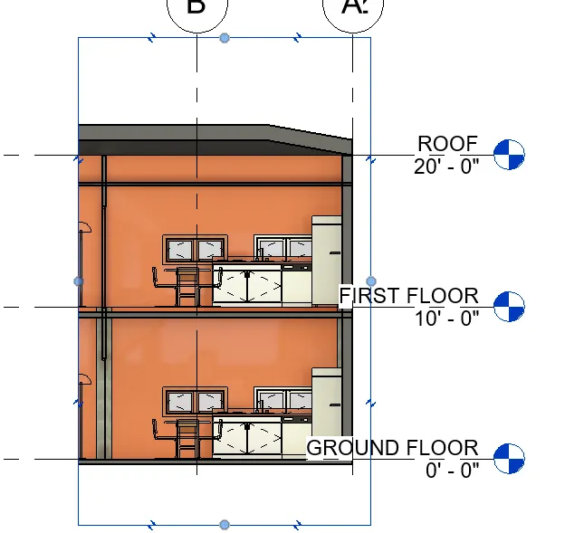
RESULT
created section views of a model in the revit
--------------------------------------------------------------------------------------------------------------------------------------------
8.AIM
To Classify the views, Plan Views, Section Views, and Elevation views to either Design or Documentation category using Properties browser
INTRODUCTION
- Autodesk Revit is a building information modelling software tool for architects , landscape architects , structural engineers , mechancial, electrical and plumbing (MEP) engineers, designers and contractors .
- The software allows users to design a building and structure and its component in 3D , annotate the model with 2D drafting elements , and access the building information from the building model's database.
- The revit sotware offers the following
- Revit customization and support
- Revit plugin development
- Revit mobile app development
- Custom Revit add-ins for MEP
- Some of the major advantages of revit are as follows
- parametric modelling
- collaboration
- coordination
- scheduling
- energy analysis
- rendering presentation
- construction documentation
PROCEDURE
STEP1
- Open revit software
- from the recent files select WEEK 4 PROJECT
STEP2
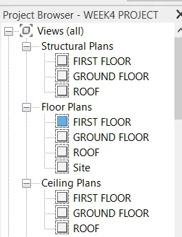
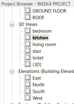
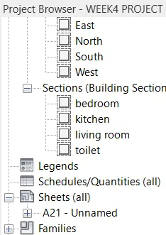
- First we open the project browser , the views , plan view, section views , and elevation views are visible in that project browser
RESULT
Views are classified as per the project browser
--------------------------------------------------------------------------------------------------------------------------------------------
9.AIM
To create multiple sheets
INTRODUCTION
- A sheet view in revit is a layout where you can place : A title block , multiple drawings, multiple schedules
- In revit using sheet template we can create sheet view of construction document
- We can place multiple drawings or schedules on each sheet view
PROCEDURE
STEP1
- Open revit software
- from the recent files select WEEK 4 PROJECT
STEP2
- Go to the project browser and then click on sheets
- Right click to add a new sheet or click on the plus sign to open the previously produced sheets
- Add view to the template
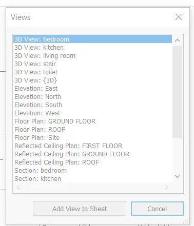
- rename the template with respective view
STEP3
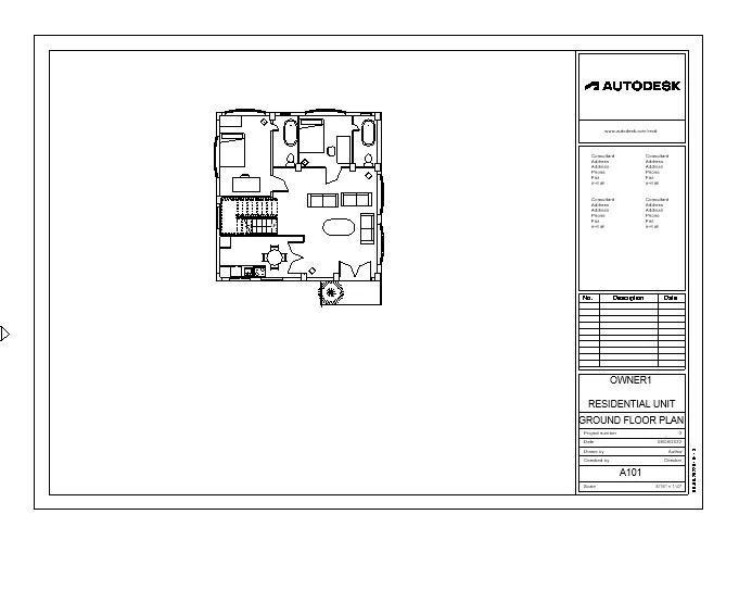
- A 101- Ground Floor Architecture Plan
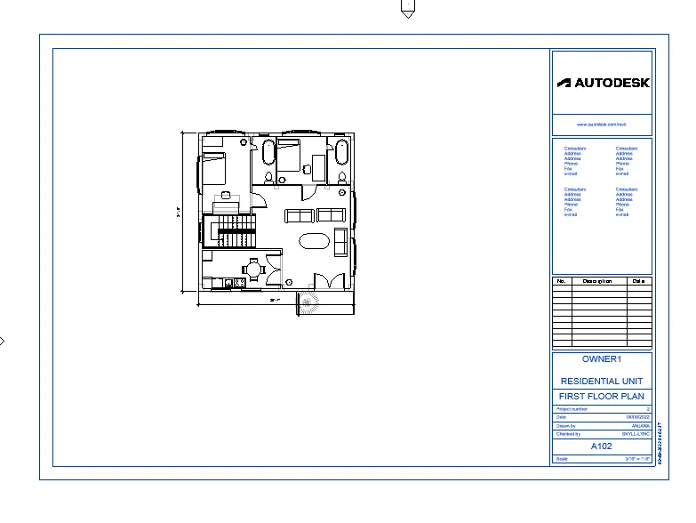
- A 102- First Floor Architecture Plan
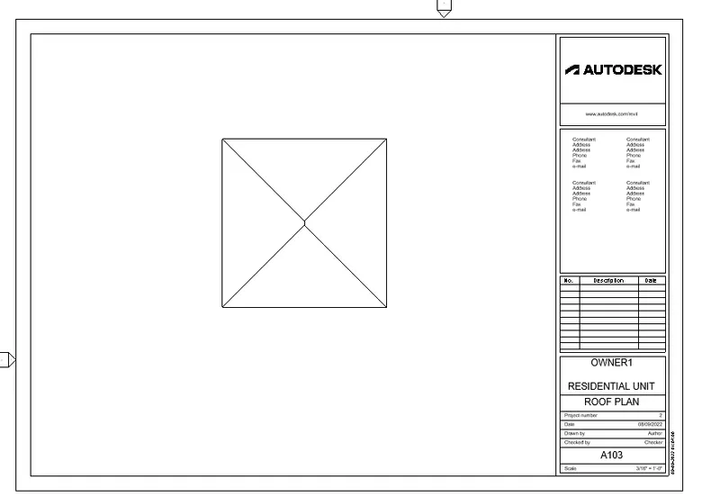
- A 103- Roof Plan
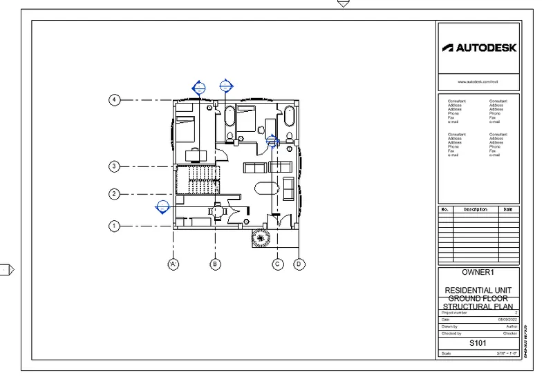
- S 101- Ground Floor Structural Plan
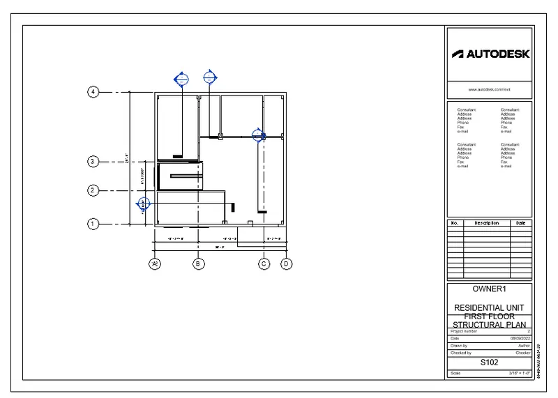
- . S 102- First Floor Structural Plan
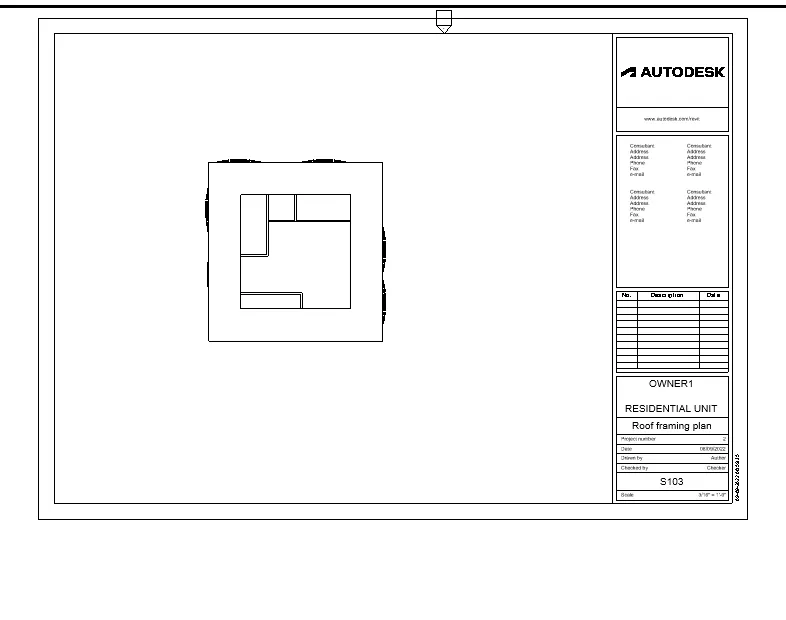
- S 103- Roof Framing Plan
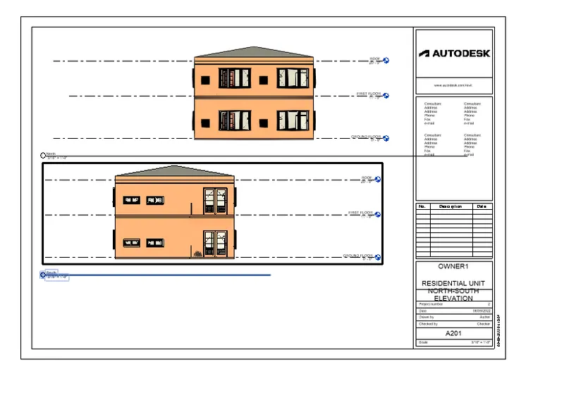
- A-201- North-South Elevations
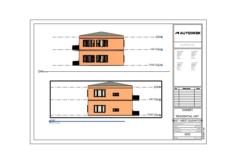
- A-202- East-West Elevations
RESULT
All the sheet templates are created with their respective views
- A 101- Ground Floor Architecture Plan
- A 102- First Floor Architecture Plan
- A 103- Roof Plan
- S 101- Ground Floor Structural Plan
- . S 102- First Floor Structural Plan
- S 103- Roof Framing Plan
- A-201- North-South Elevations
- A-202- East-West Elevations
-----------------------------------------------------------------------------------------------------------------------------------------
10.AIM
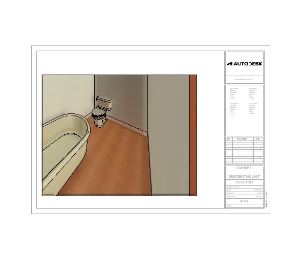
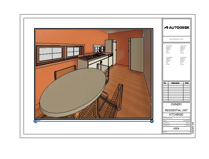
To Create a camera-specific view or a 3D view in each room
INTRODUCTION
- A sheet view in revit is a layout where you can place : A title block , multiple drawings, multiple schedules
- In revit using sheet template we can create sheet view of construction document
- We can place multiple drawings or schedules on each sheet view
PROCEDURE
STEP1
- Open revit software
- from the recent files select WEEK 4 PROJECT
STEP2
CREATING 3D VIEW
- Go to the view tab
- click on 3D view and click on camera
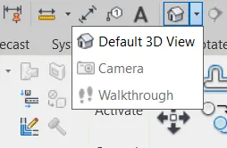
- set the point for the camera on the required location and give the direction to the camera
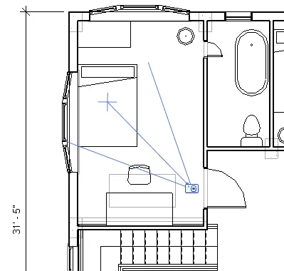
- Go to the project browser and then click on sheets
- Right click to add a new sheet or click on the plus sign to open the previously produced sheets
- Add view to the template
- rename the template with respective view
RESULT
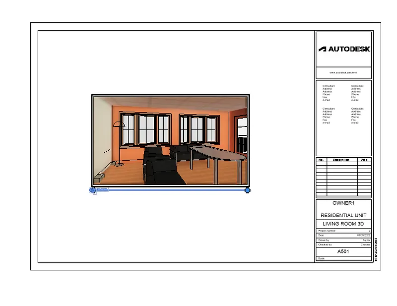
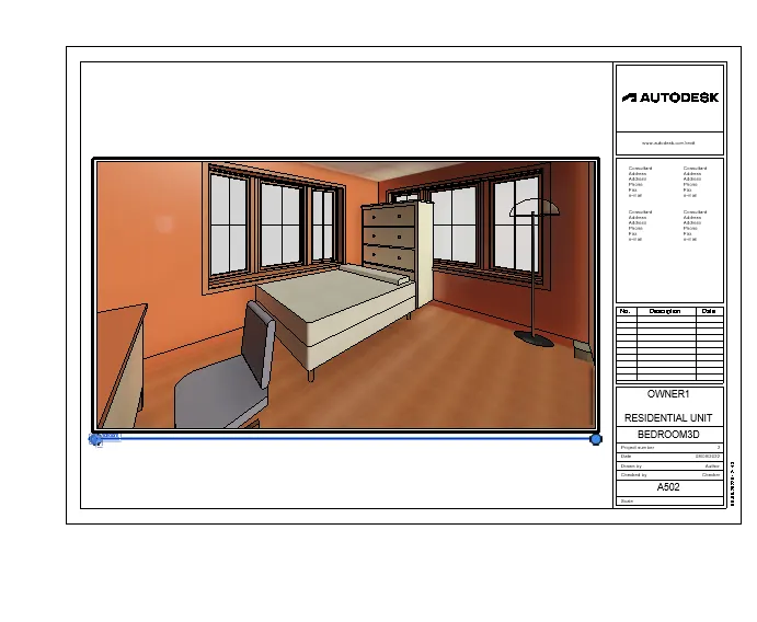
Following different 3D cam views are created
- A 501 LIVING ROOM3D
- A 502 BEDROOM3D
- A503 TOILET 3D
- A504 KITCHEN 3D
------------------------------------------------------------------------------------------------------------------------------------------