3D Creation of Celing, Roof, Architectural plan, Structural plan, Sectional view, Elevation view and Camera specific view for a house plan using REVIT
1.)
Aim
To model a ceiling above the walls at the first floor level in revit
Tools used Archietectural & ceiling tab
Introduction
- The flor paln is created.Based on the project saved from Week 3, proceed from the First Floor Level. Model a Ceiling from the architecture tab above the walls at the first-floor level
Procedure
- Open a ceiling plan view.
- Click Archeitectural tab buiid panel(ceiling).
- In thwe type sector select a ceiling type.
- Place the ceiling by using one of the method: Use walls as opening boundaries,by default,the automstic ceiling tool is active.
- By default,the automstic celing tool is activated
- When you click inside walls that form a closed loop,the toolplaces a ceiling boundaries
Result
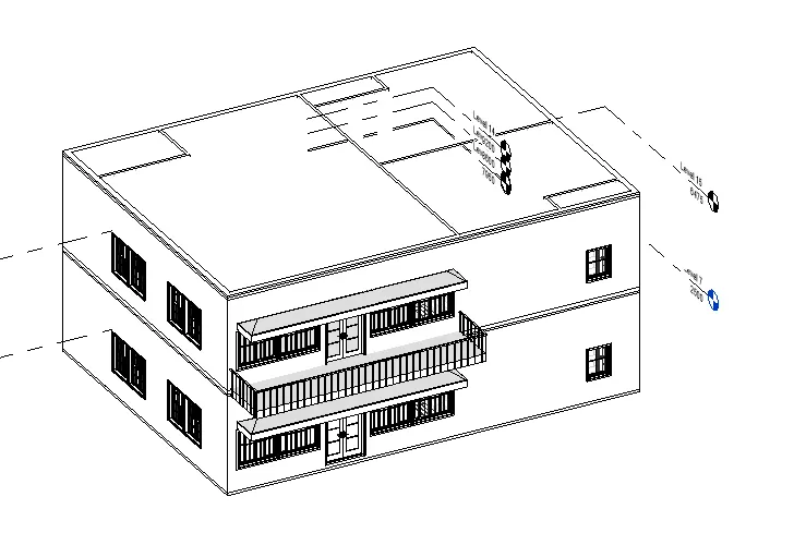
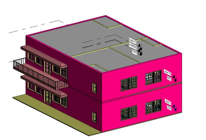
- Thwe ceiling is placed on the first floor walls as shown
2.
Aim
- To creat a roof above the ceiling at the first-floor level in revit.
Tools used:archietectural tab,roof,footprints.
Introduction
- The roof is created.Model a roof above the ceiling by selecting the footprints of the ceiling. Using the adjustment toolbars appearing on-screen adjust the roof slope to 10 degrees
Procedure
- Display a floor plan view or a reflected ceiling plan view
- Click archeitectural tab build panel roof drop-down
- On the draw panel,select a sketch or pick tool
- Sketch,or pickclosed loop for the roof
- Specify the slope defining lines
- By default , the automatic ceiling tool is activated
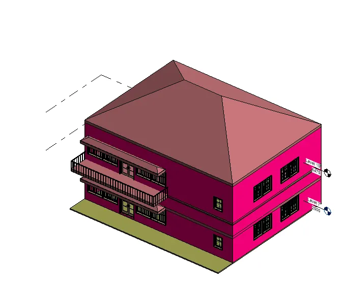
- Roof is placed
Result
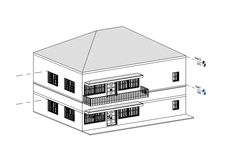
The roof is created by using footprint
3.
Aim
- Create plan views for ground floors level and first-floor level imcluding all the walls floors and components
Tools used : view tab ,view
Introduction
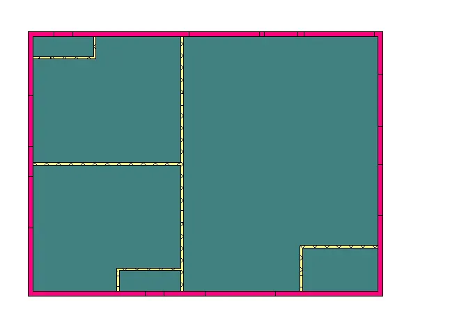
- Using the file saved from weeks 2 to 4, create plan views for ground floor level and first-floor level including all the walls, floors, and components. Separate them to
architecture and structural plans
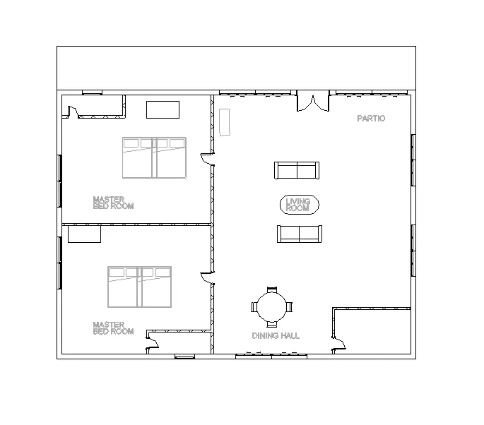
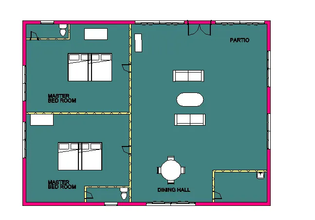
a. Architecture plan must have walls, floors, and all the components placed within the building
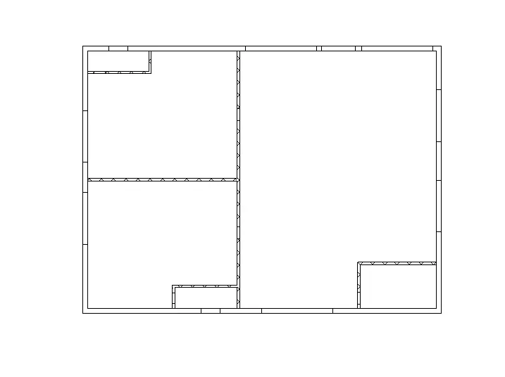
b. Structure plan must have details of only walls, floors, and columns
Procedure
- The plan is already drawn in the project 3 any how we need to seprate the drawings
- In the archetectural drawing all the components are shown
- like furniture,lightings,plumbings are etc
- And windows and doors also vissible
- In the structural all the components are vissible
a.)
b.
4.)
Aim
- To Aded dimensions to all the walls and floors with refrence to the longitudinal and transverse grids
Tools used : Annotate and alined
Introduction
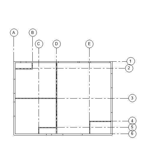
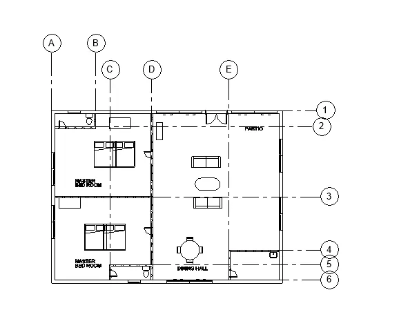
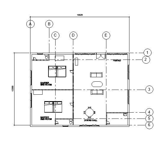
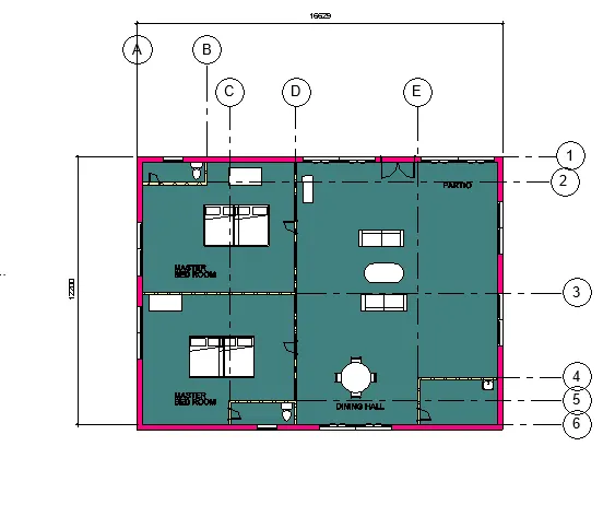
- Using annotate toolbar add dimensions to all the walls and floors with reference to the longitudinal and transverse grids created in the project file
a. The architecture plan dimensions include details on where the components are placed within the buildings with relation to grids. Overall dimensions are sufficient for architecture plans
b. The Structure plan dimensions must include details on the position of all the walls and interior walls with reference to grids. Locate all the framing components of the building with reference to a fixed point using Structural plans
procedure
- Click annotate tab dimensions panel linear.find.
- Specfy the first and second extention line orgin.
- click a place the dimension line
- click and placew the dimension line
a.)
b.)
5.)
Aim
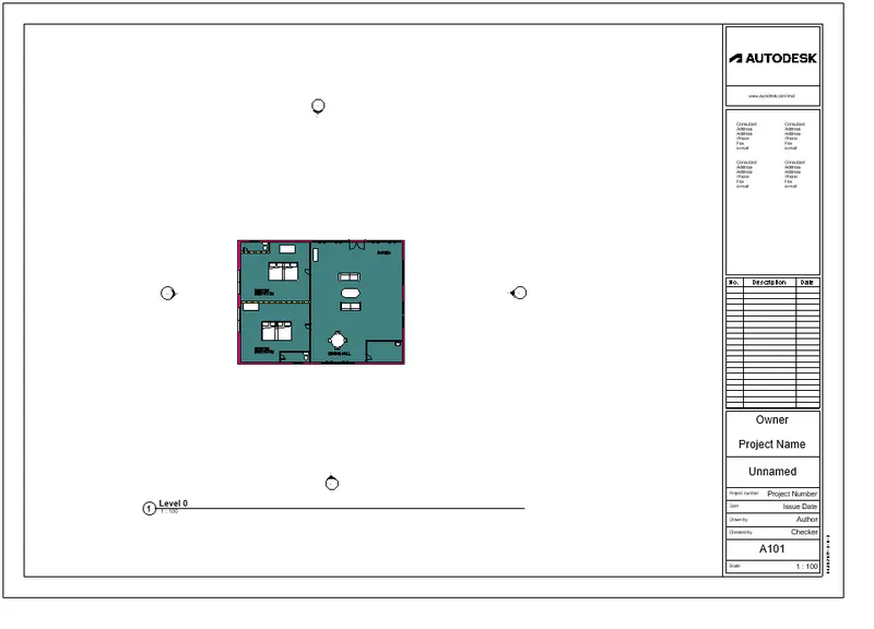
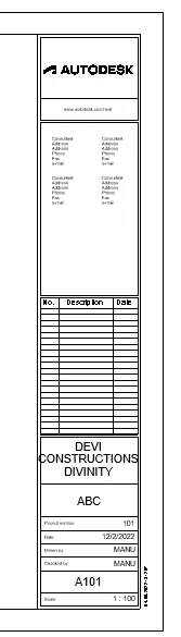
- To creat a sheet template to the project template list
Tools used view tab ,view
Introduction
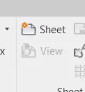
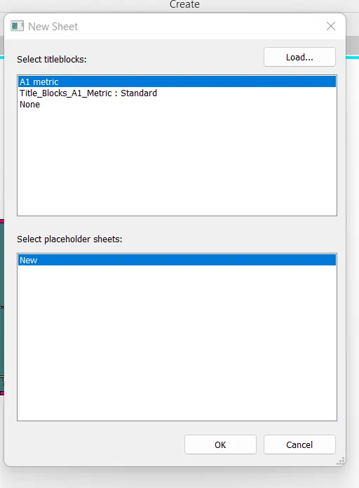
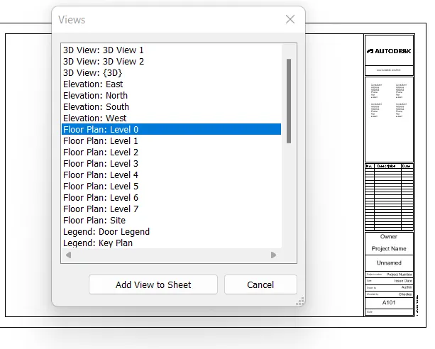
- Create a sheet template from the view tab and adjust the parameters on the sheet to add appropriate views
Procedure
- To add project template to the project template files list,as follows
- Creat the project templates that you want to include in the list
- Click file tab
- click the file locations tab
- add one or more tamplates to the project template files list
- templste is added to the list
- location all sre setted
- providing quick acess to the project
Result
The sheet template is created.
6.)
AIM
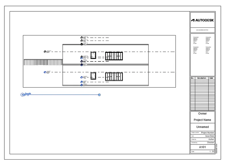
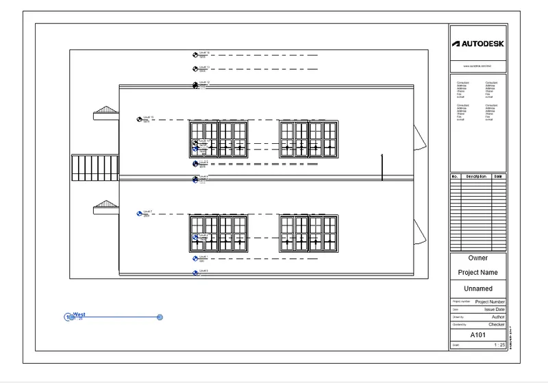
- Creat the elvetion view looking at esst west north south
Tools used: viewtab,elevation
Introduction
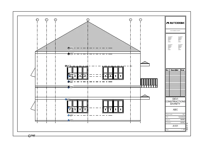
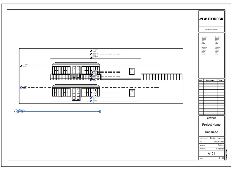
- Using the elevation tab create the elevation views, looking at your building from East, North, South, and West
procedure
- Open a plan view
- click view tab-creat-panelelevation drop-down elevation
- The cursor appears with the elevation symbol
- editing is done
to set diffrent interior elevation views,hightliting the square shape of the elevation
- Highligth ann arrowed on the symbol to select it
- click the arrowed once to view the clip plane
- instance properties dialog,selectiom the crop view parametersand click ok
- In the project browser,selection the new elevation view
- the elevetion view is designed by a letter and number for example elevation-a
Result
the elevation view is done
7.)
Aim
To creat the section cut through each room either cutting across longitudinal transverse direction
Tools used : view tab,section
Introduction
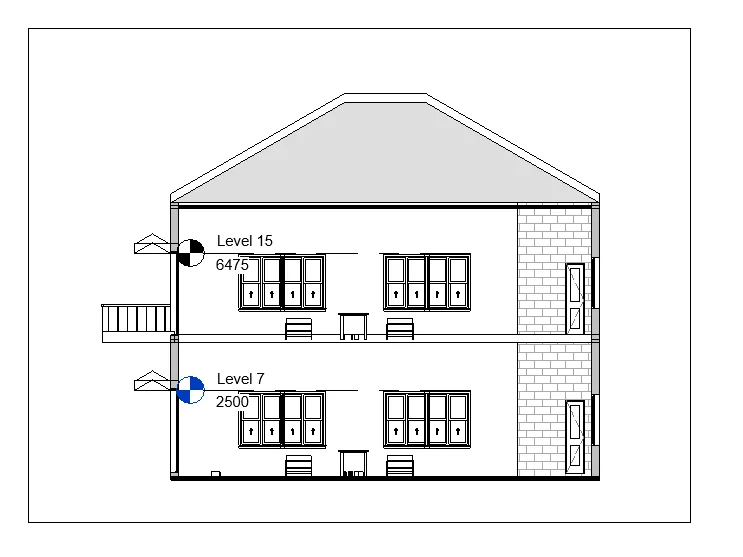
- Produce section cut through each room either cutting across longitudinally or in a transverse direction
procedure
- open a plane section,elevation or detail view
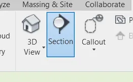
- click view tab creat panel
- In the type selector,select a view typre from the list
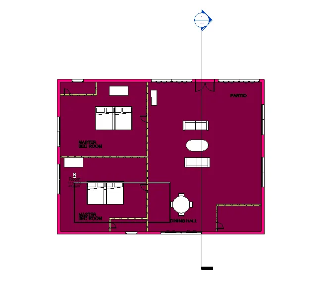
- place the cursor of the starting point of the section and drag throuhj the model or familty
- Note you can snap a section line parallel or perpendicular to a non-orthogonasl datum
- click when you reach the end point of the screen
- The section line and thre crop region appear and are selected
- Click modify or press escto exit the section tool
- To open the section view,double-click the selection header,or select the section view from the sections grouping of the project browser
- The sections view change when the design changes of the section line isn moved
Result
The section view is produced
8.)
Aim
- Creat the views,plansviews,and elevation views to either design
- Tools used : properties,section
Introduction
- Classify the views, Plan Views, Section Views, and Elevation views to either Design or Documentation category using Properties browser
Procedure
- open a plan view
- click viewtab-creat-panel elevation drop-down(elevation)
- cursor appears with the elevation symbol
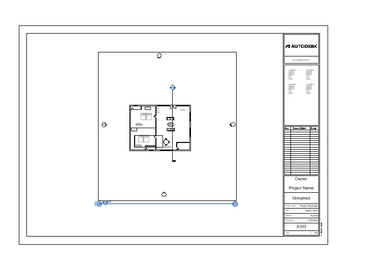
- Elevation symbols displays with create box option for creating views as the following images shown
- click away from the elevation su=ymbol to hoide the check boxes
- select the check boxed to indicate hwtre you want to creat elevations
Result
9.)
Aim
- To creat the sheet template to the project template list
Tools used viewsheet,selection,view
Introduction
- Using the sheet template produced create multiple sheets as follows
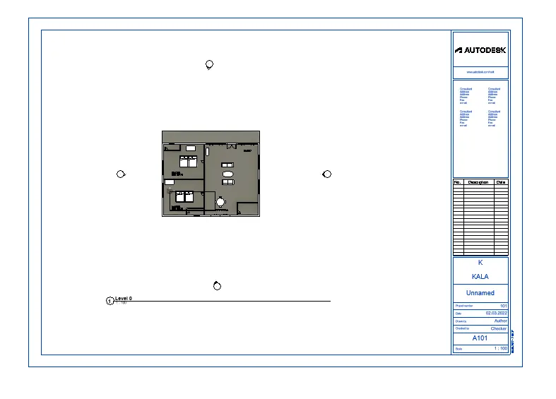
a. A 101- Ground Floor Architecture Plan
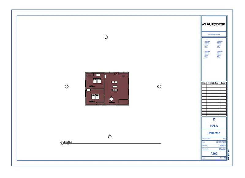
b. A 102- First Floor Architecture Plan
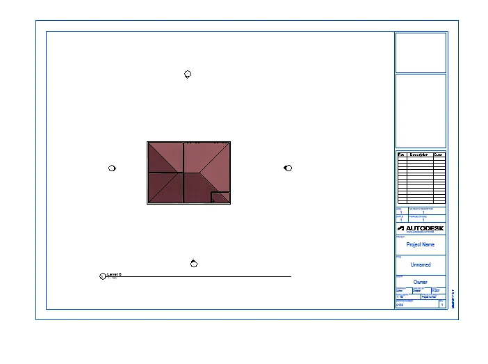
c. A 103- Roof Plan
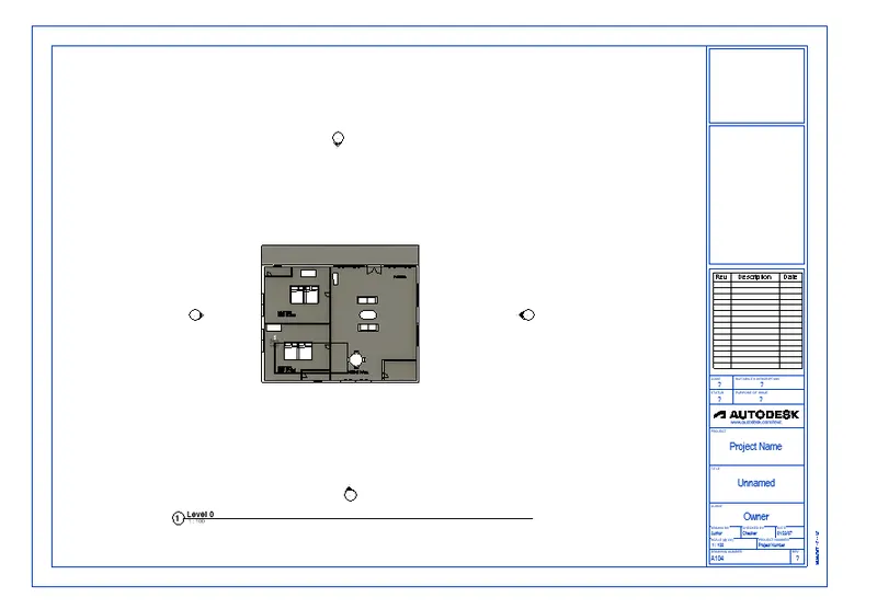
d. S 101- Ground Floor Structural Plan
e. S 102- First Floor Structural Plan
f. S 103- Roof Framing Plan
g. A-201- North-South Elevations
h. A-202- East-West Elevations
Add additional sheets based on the sections created in your Revit file
Procedure
- To add project template to the project template list
- Create the project templates that you want to include in the list
- Click file tab
- Add one or more templates to the project twmplates files list,as follows
- click file button
- Click the file location tab
- click(add value)
a.)101 Ground floor architectural plan
b.)102 Second floor architectural plan
- click the file location tab
- add one or more templates
- Navigate to the project template file select at and click open
- under name replace template files isn done
c.) 103 roof plan
d.) Ground floor structural plan
e,North easr plan
- The first templates listed in the table will appear on the recent file window under projects
- Providing quick acesss
F.) East west plan
10.)
Aim
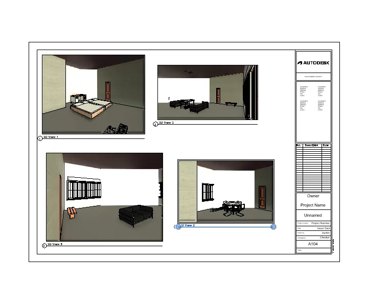
- Creat a camera specific view or a 3D view in each room (living,dining,bedroom)
Tools used :view,sheet,slection,viewsheet,camers
Introduction
- Create a camera-specific view or a 3D view in each room ( living, dining, bedroom). Based on the views create a new set of sheets starting A-501 (you can add as many sheets after, 502, 503.. n)to place the 3D view images. Produce the sheets as a part of project drafting.
Procedure
- After creating your 3d model in revit of course,you want to show off your model
- click the small arrow near thr 3d views and click the camers button on the drop-down
- placing of camera,you can place a camera by activating it from your ribbons,view tab menu
- Make sure modify is active,click the view boundary.you will see the blue grips on the rectangle sides
- After you define the camera by two clicks:the camera position and trget position.
- Bird eye view thsts how we can place the camera,pretty eassy
- but before you define the position,look at the option bar
Result
View obatined by placing a camera views in each room is placed in the template.