3D Creation of Celing, Roof, Architectural plan, Structural plan, Sectional view, Elevation view and Camera specific view for a house plan using REVIT
1) Based on the project saved from Week 3, proceed from the First Floor Level. Model a Ceiling from the architecture tab above the walls at the first-floor level
Ans 1.
INTRODUCTION: Creating ceiling from architectural tab
AIM: To create a model of ceiling from the architecture tab above walls at the first floor level
PROCEDURE:
- Open the ground floor level plan
- From Architectural tab click on the ceiling
- Place ceiling either using automatic ceiling or by sketch ceiling by selecting the boundaries
- Select the required type and size of the ceiling
- If required modify the type of ceiling
- Enter the offset of celing from ground floor
- If required provide 2 layers of ceiling design for the gypsum ceiling by sketching the boundary line
- Thus ceiling view will be formed in the property browser
- If required insert the electrical fixtures like fan, ceiling lights etc
- The screenshots of ceiling creation are shown below along with final interior view of ceiling
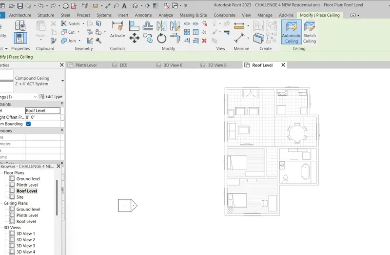
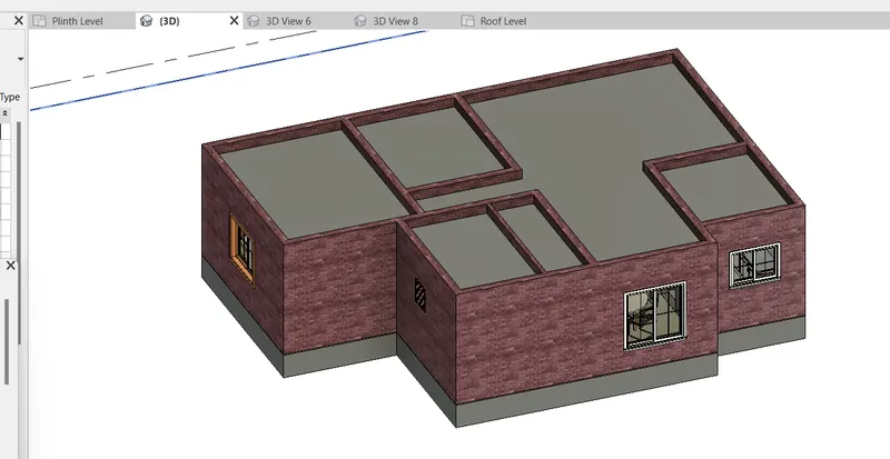
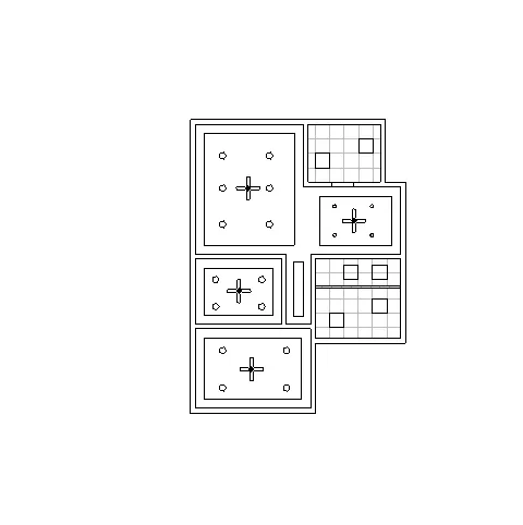
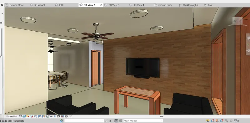
CONCLUSION: Thus we have created ceiling at first floor level using the architectural tab.
2) Model a roof above the ceiling by selecting the footprints of the ceiling. Using the adjustment toolbars appearing on-screen adjust the roof slope to 10 degrees
Ans 2.
INTRODUCTION: Creating roof above the ceiling
AIM: To create a model of roof above the ceiling from the architecture tab above walls at the first floor level and using the adjustment roolbars adjusting the slope of roof to 10 degrees
PROCEDURE:
- Open the roof/first floor plan
- From the architectural tab click on the roof and select roof by footprint
- Select the outer edge of the roof/first floor plan for creating the footprint for roof and create roof
- The slope of roof can be set to 10 degrees in the property dimensions
- Required finish can be provided by clicking on Edit type.
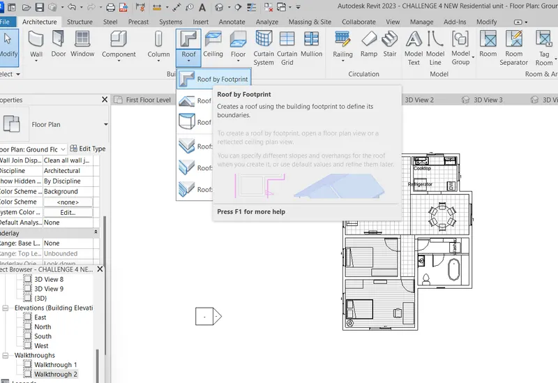
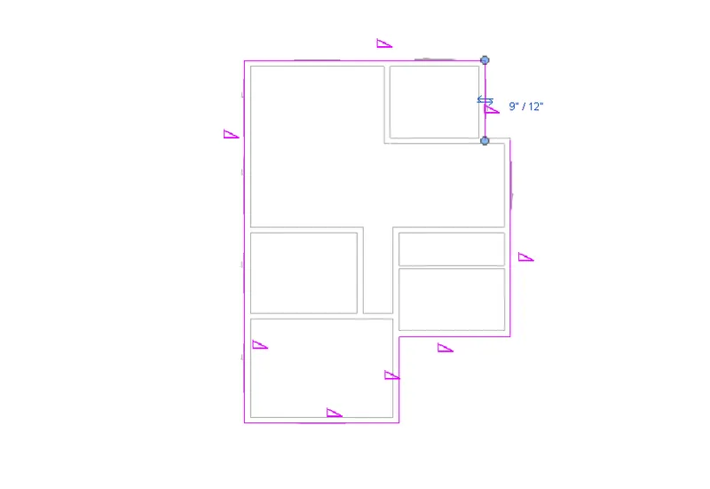
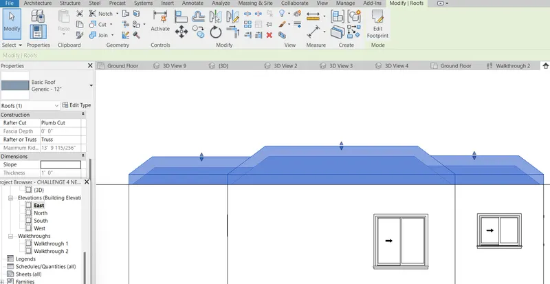
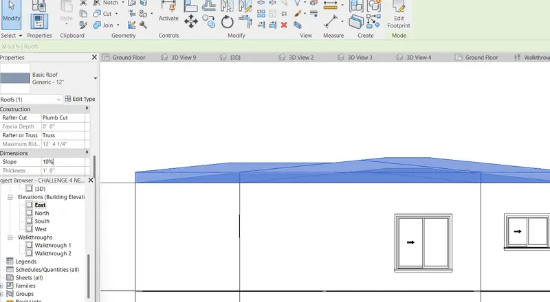
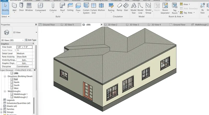
CONSLUSION: Thus we have created the roof on the first foor/roof level by using roof by footprint selection from architectural tab and changed the slope of roof to 10 degrees from the properties of roof.
3) Using the file saved from weeks 2 to 4, create plan views for ground floor level and first-floor level including all the walls, floors, and components. Separate them to
architecture and structural plans
a. Architecture plan must have walls, floors, and all the components placed within the building
b. Structure plan must have details of only walls, floors, and columns
Ans 3:
INTRODUCTION: Creating Plan views in Architectural and Structural templates
AIM: To create the architectural plan view and structural plan view for the residential plans created in our previous project.
PROCEDURE:
- Open the ground floor plan of our previous residential building project
- Click on the View Tab and select planviews
- Five types of plan views option window will be opened
- Click on the Floor Plan
- There is no list of new plan to be created as we have already created the Plan views for the architectural template
- Close the New plan view window by clicking OK or Cancel tab and the project template in properties can be selected to Architectural template
- Select the Structural plan in Plan View window
- The list of all the architectural plans will be available
- Select the required floor plan to create the structural plan
- The selected plan will be created in the structrural plan view
- In properties window select the View template to Structural and only structural elements will be visible in the structural plan view created.
- The screenshots for the procedure are shown below
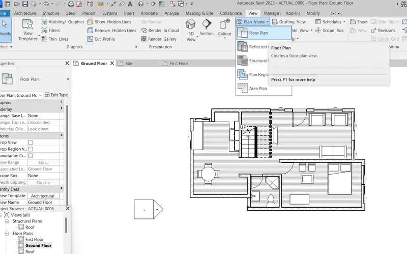
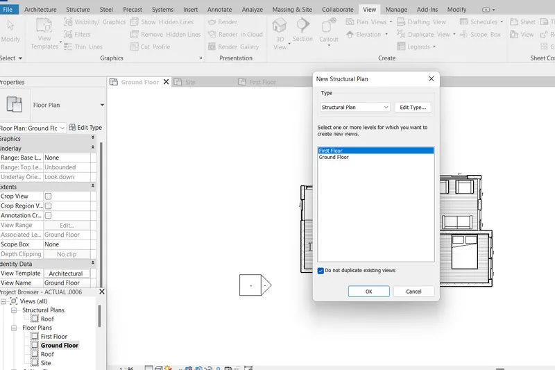
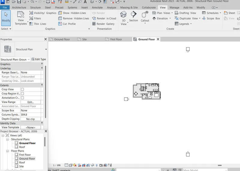
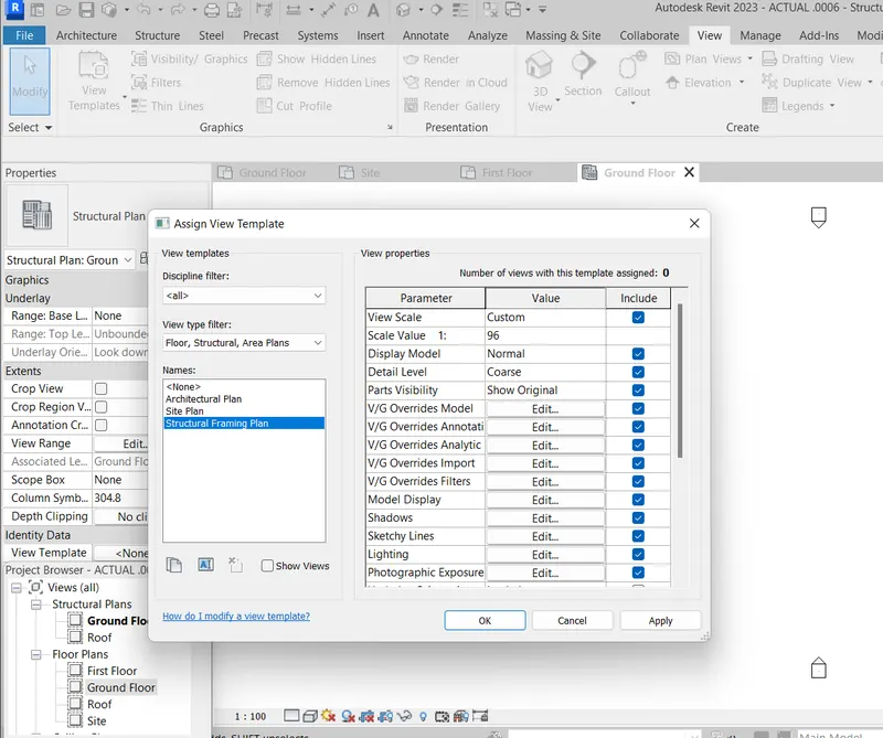
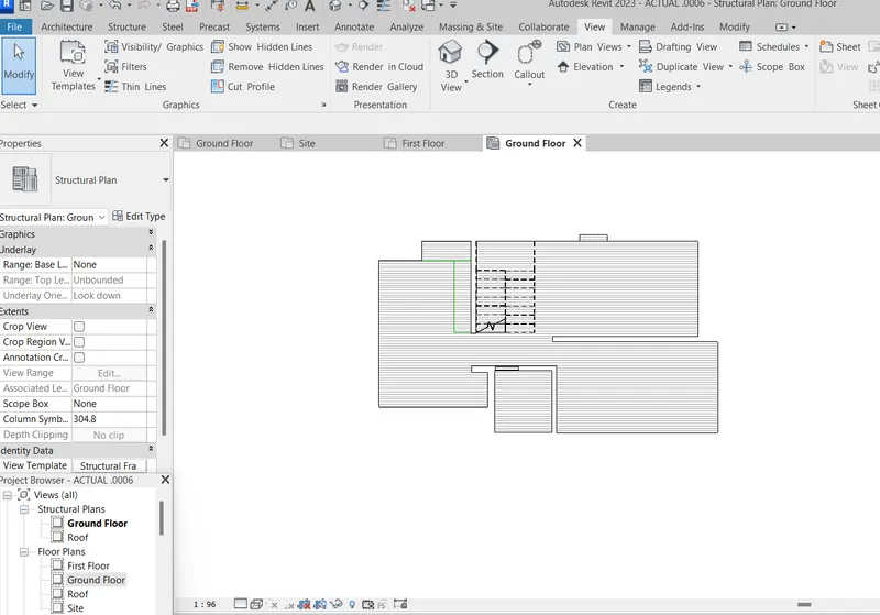
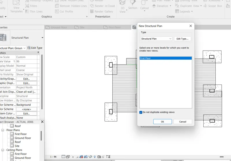
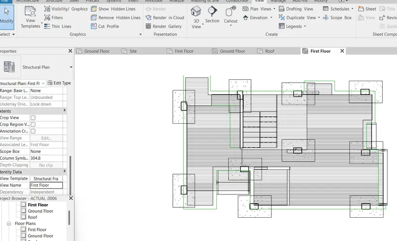
CONCLUSION: Thus we have created the architectural plan view and structural plan view from the Plan Views tab using the Architectural and Structural template views.
4) Using annotate toolbar add dimensions to all the walls and floors with reference to the longitudinal and transverse grids created in the project file
a. The architecture plan dimensions include details on where the components are placed within the buildings with relation to grids. Overall dimensions are sufficient for architecture plans
b. The Structure plan dimensions must include details on the position of all the walls and interior walls with reference to grids. Locate all the framing components of the building with reference to a fixed point using Structural plans
Ans 4.
INTRODUCTION: Providing the dimensions to walls and floors in architectural plan and strucutural plan using annotate toolbar
AIM: To provide the dimensions to the architectural plan and structural plan using annotate toolbar with reference to the transverse and longitudinal grids created in the project file.
PROCEDURE:
- Open the architectural plan
- Provide grid lines with grid configuration as per wall centres
- Using annotate tab provide the dimensions using wall centre or wall face to the grid lines
- Similarly open the structural plan view and provide the dimensions using annotate tab
- The screenshots for the dimensions with grid lines are shown below.
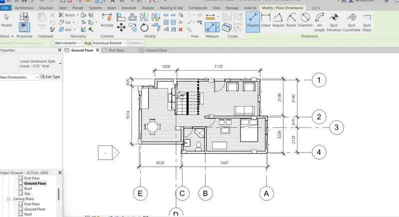
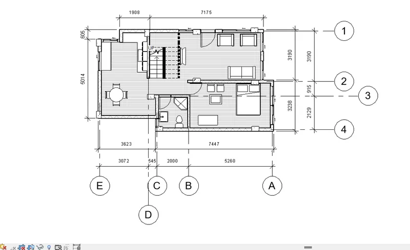
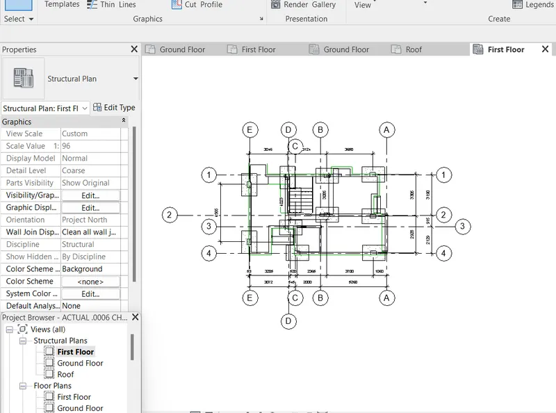
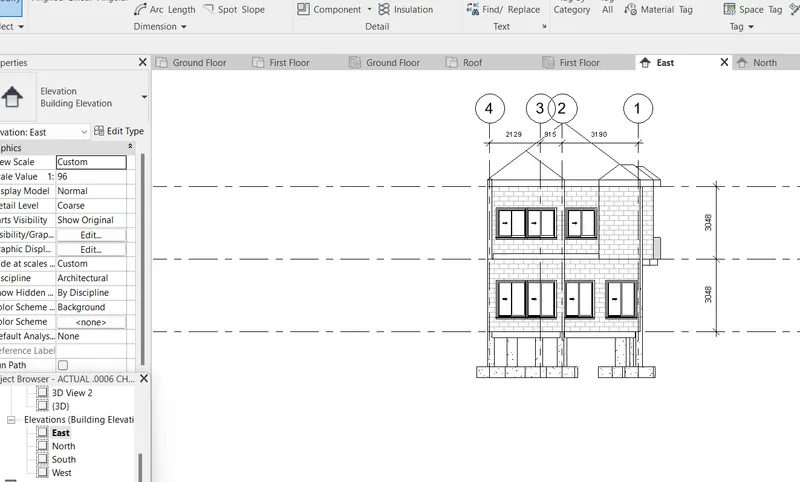
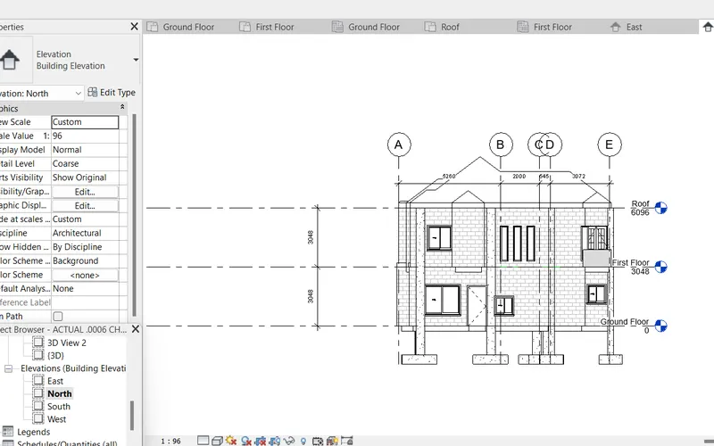
CONCLUSION: Thus we have provided the dimensions to the Architectural plan and structural plans and elevations by providing the grid lines.
5) Create a sheet template from the view tab and adjust the parameters on the sheet to add appropriate views
Ans 5.
INTRODUCTION: To creat Sheet template from View tab
AIM: To create the sheet template from the view tab and setting the plan in the sheet and editing the title block.
PROCEDURE:
- Go to the View tab
- Click on the sheet icon
- Select the Template from the opened window
- If required load the required template from the Autodesk family
- Drag the required drawing to the template sheet and place at the required position
- Or the drawing can be placed by clicking Place view tab
- Adjust the scale to set the drawing on the sheet
- If the View scale is not visible then change the drawing template to None or set the scale in the drawing view.
- Edit the title block details or the Parameters entered in the Project information will automatically be shown in the title block
- Below are the screenshots of the Sheets created
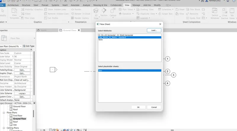
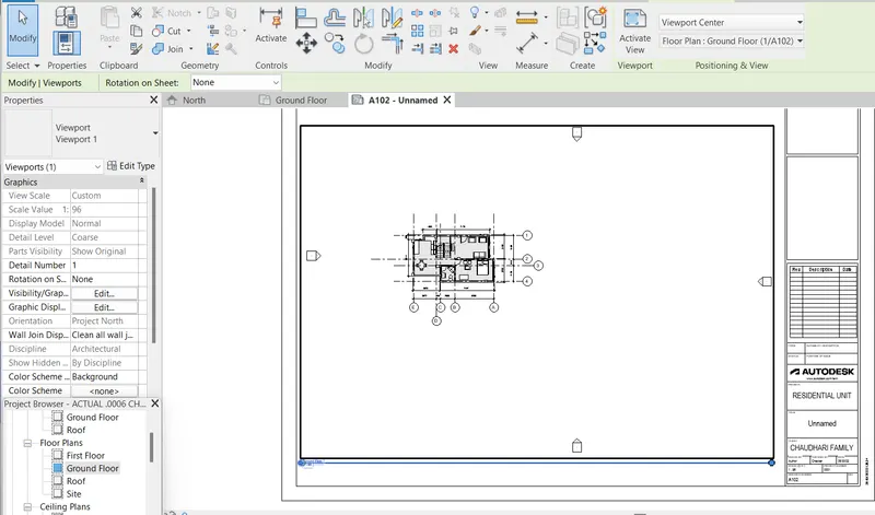
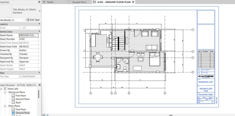
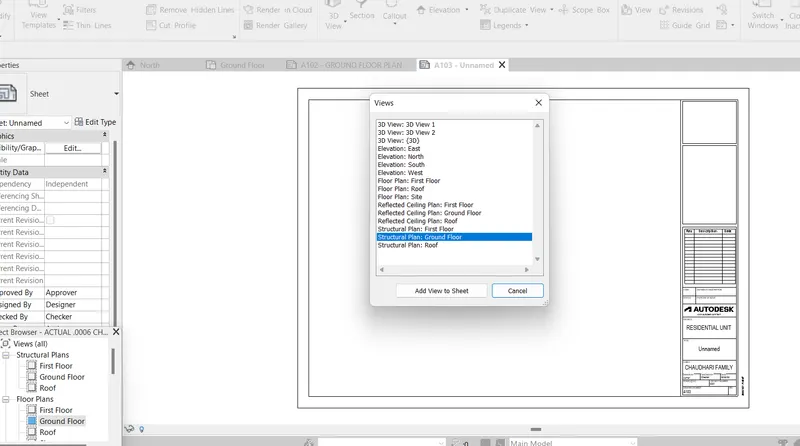
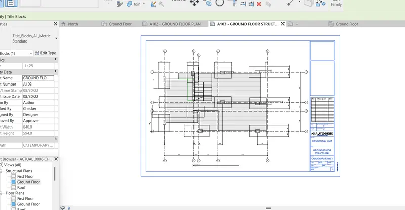
CONCLUSION: Thus we have create the Sheet with title blocks for the ground floor Architectural and structural plans and edited the project title details.
6) Using the elevation tab create the elevation views, looking at your building from East, North, South, and West
Ans 6.
INTRODUCTION: Creating Elevation views
AIM: To create the elevation views using the elevation tab looking from the East, West, North & South directions of the building.
PROCEDURE:
- If the Elevation views are not available in the project browser then on the plan view go to the View tab
- On view tab select the Elevation icon
- The arrow pointer will be formed, place it on the required side of the elevation
- Now the Elevation views of placed elevation will appear on the project browser
- The elevation view can be renamed to East, West , North & South as per the directions of the views
- Screenshots of elevation creation shown below
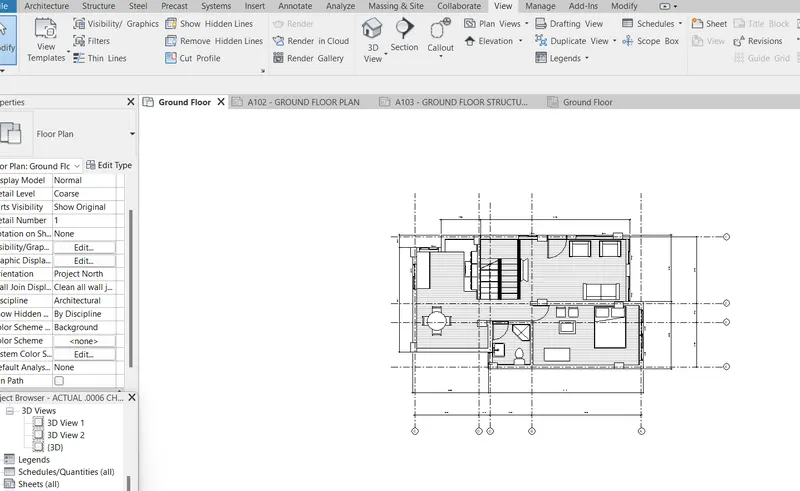
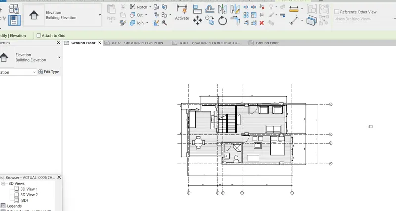
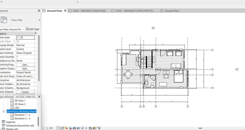
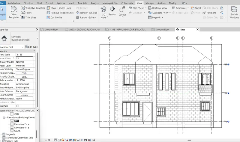
CONCLUSION: Thus we have created the elevation views using the View tab and renamed them to East,West, North & South.
7) Produce section cut through each room either cutting across longitudinally or in a transverse direction
Ans 7.
INTRODUCTION: Creating Section views
AIM: To create the transverse and longitudinal section views passing through the rooms using the Section view from the View tab.
PROCEDURE:
- On the plan view go to the View tab
- On view tab select the Section icon
- The section line with direction of section will be formed, place it on the required line on the plan
- Now the Section views of placed section line will appear on the project browser
- The Section view can be renamed to as per the grid lines or room names
- Screenshots of Section creation are shown below
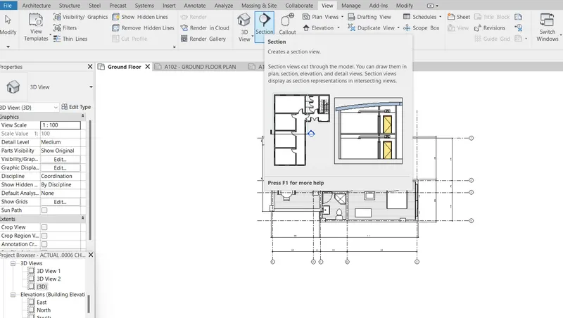
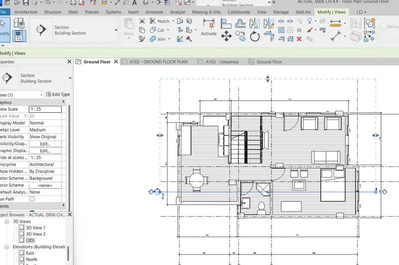
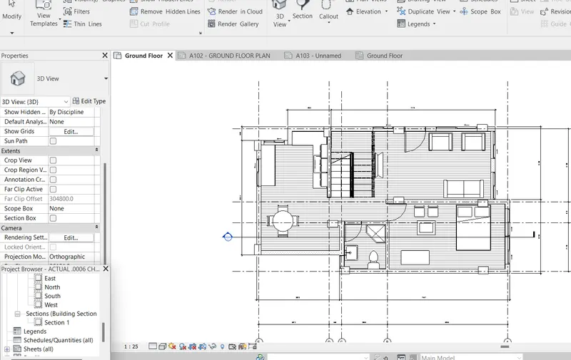
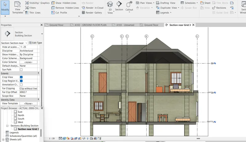
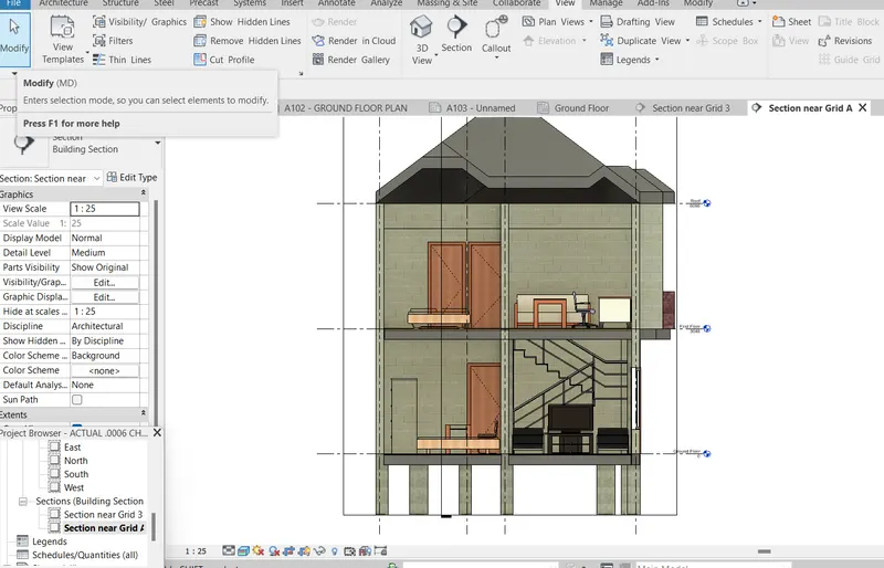
CONCLUSION: Thus we have created the Section views in transverse as well as longitudinal direction using the View tab and renamed them with reference to the grid lines.
8) Classify the views, Plan Views, Section Views, and Elevation views to either Design or Documentation category using Properties browser
Ans 8.
INTRODUCTION: Classification of the Views in Project Browser
AIM : To classify various views like Plan views, Section views, Elevation views etc using the project browser.
PROCEDURE:
- As we create various drawing views in revit, the list of the views is created in the project browser
- The list can be used to open various views for further use.
- The list can be collapsed or expanded as details available
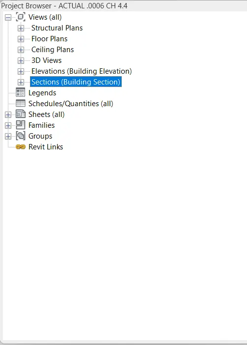
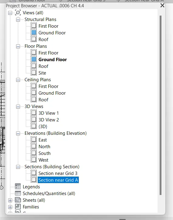
CONCLUSION: Thus the classification of the various views created like Structural Plan views, Floor Plan Views, Elevation views, Section views etc, in the Project browser are shown in the screenshot.
9) Using the sheet template produced create multiple sheets as follows
a. A 101- Ground Floor Architecture Plan
b. A 102- First Floor Architecture Plan
c. A 103- Roof Plan
d. S 101- Ground Floor Structural Plan
e. S 102- First Floor Structural Plan
f. S 103- Roof Framing Plan
g. A-201- North-South Elevations
h. A-202- East-West Elevations
Add additional sheets based on the sections created in your Revit file
Ans 9.
INTRODUCTION: Creating multiple sheets using sheet template
AIM: To create the multiple sheets for architectural plans, structural plans and elevations using the sheet template created.
PROCEDURE:
- From the earlier created Sheet template for ground floor architectural and structural plans the other floor plans sheets can be created
- Click on the required sheet and edit the drawing number and drawing name
- From sheet duplicate the blank sheet template
- Insert the other floor drawings by dragging or Place View tab and edit the name of the drawing and ensure the required drawing number given to the sheet.
- For the 2 elevation views on same sheet adjust the drawing scale accordingly
- Screen shots are shown for the sheet samples and the list of sheets created
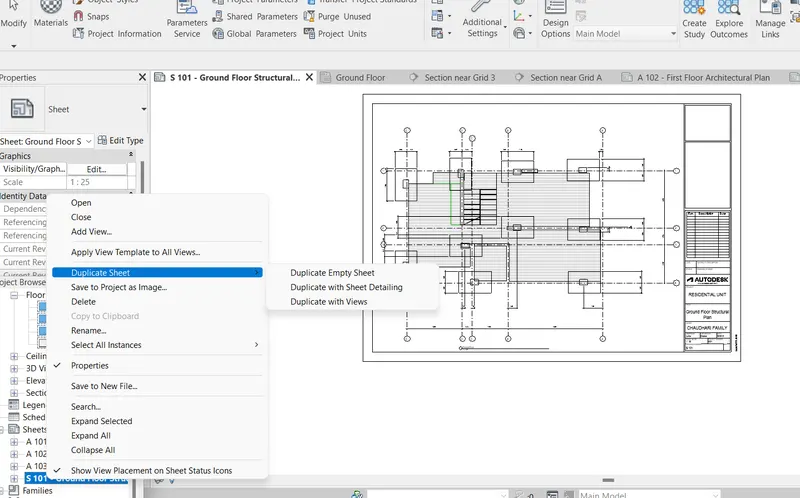
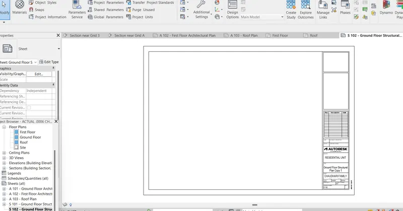
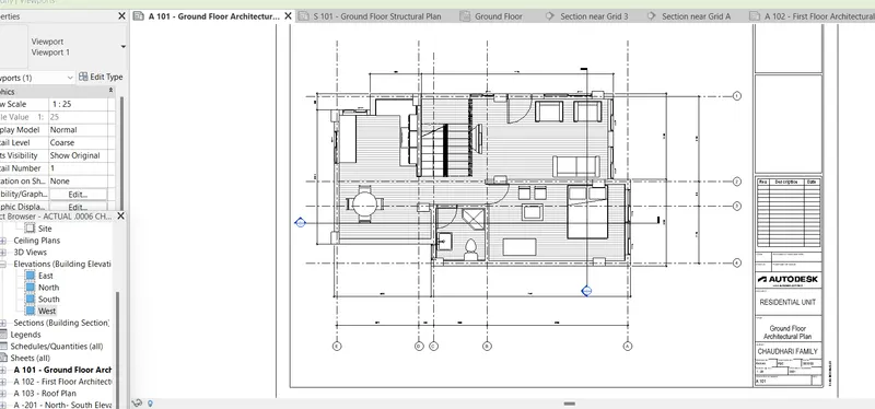
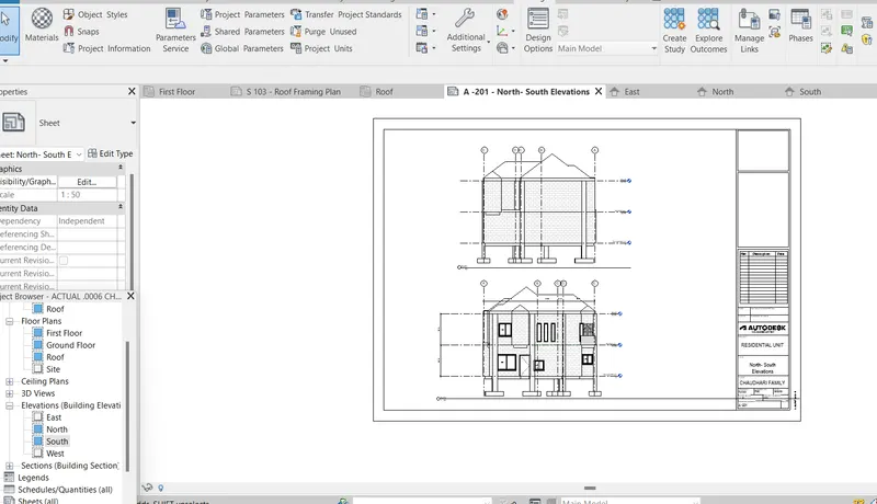
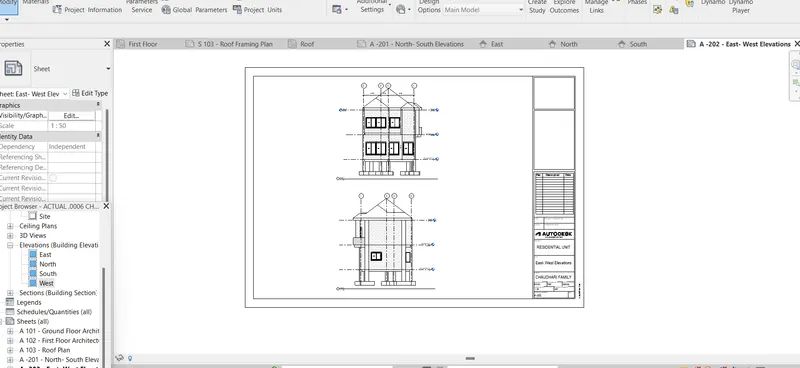
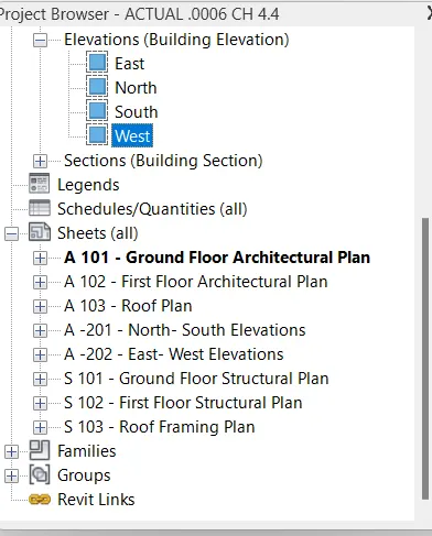
CONCLUSION: Thus we have created the multiple sheets for the architectural plans, structural plans and elevations using the sheet template create and naming as per the given drawing number and names.
10) Create a camera-specific view or a 3D view in each room ( living, dining, bedroom). Based on the views create a new set of sheets starting A-501 (you can add as many sheets after, 502, 503.. n)to place the 3D view images. Produce the sheets as a part of project drafting.
Ans 10.
INTRODUCTION: Creating camera specific 3D views inside rooms and adding to the sheets for the views
AIM: To create the 3D view using camera inside the rooms and creating sheets for the camera specific views for Living room, Kitchen/Dining and Bedroom views.
PROCEDURE:
- Go to the plan view of the residential unit
- Select the Camera from the 3D view tab
- Place the camera inside the room so as to get proper view of the room interior
- Thus the 3D view will be created for that room which can be renamed in the project browser
- Create the 3D views for each room
- Now select the previous sheet created and duplicate the template and provide the drawing name for room view and change drawing number to A-501
- Drag the 3D view of room from project browser or place using Place view option for sheet in View tab.
- Adjust the viewport size by Crop view option to fit the paper by entering the dimensions for field view or providing a suitable number for the Scale
- Thus the Sheet for the 3Dview is created in the project browser.
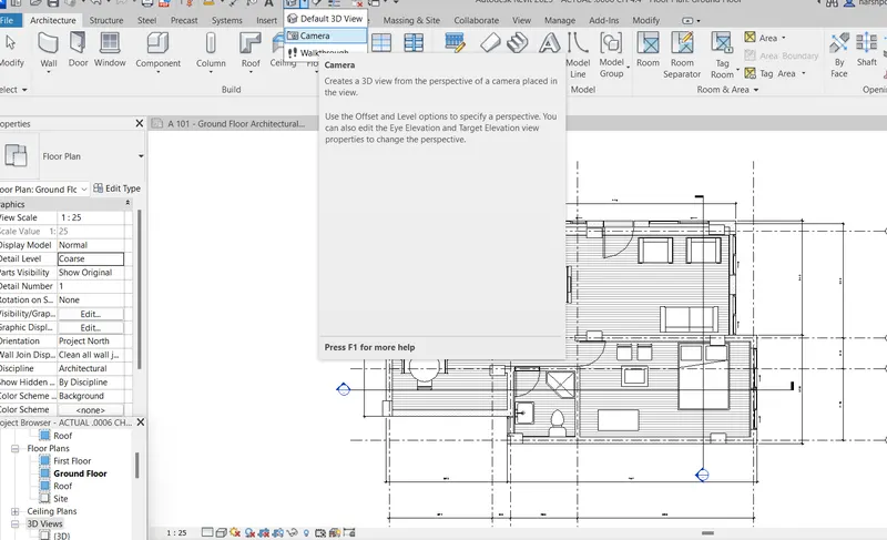
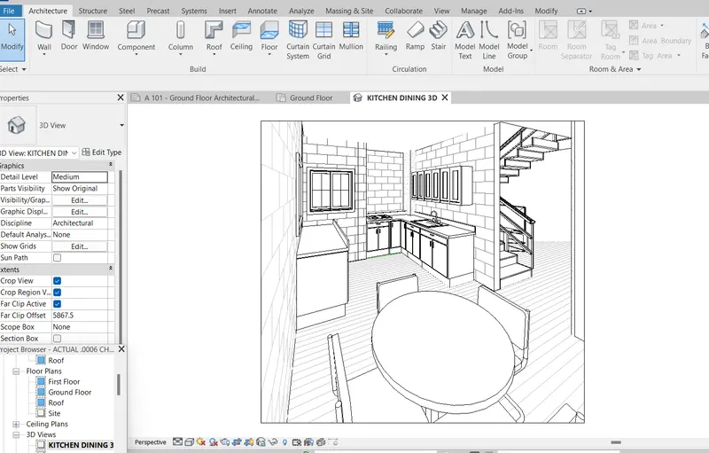
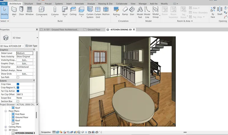
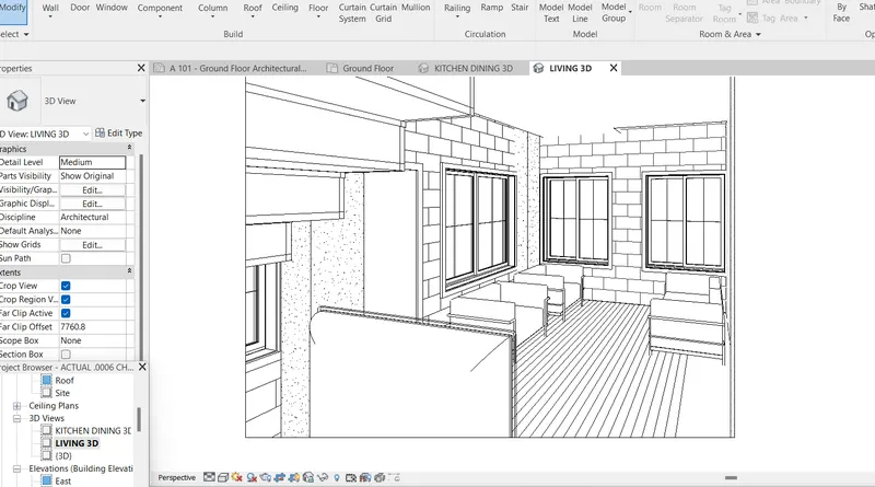
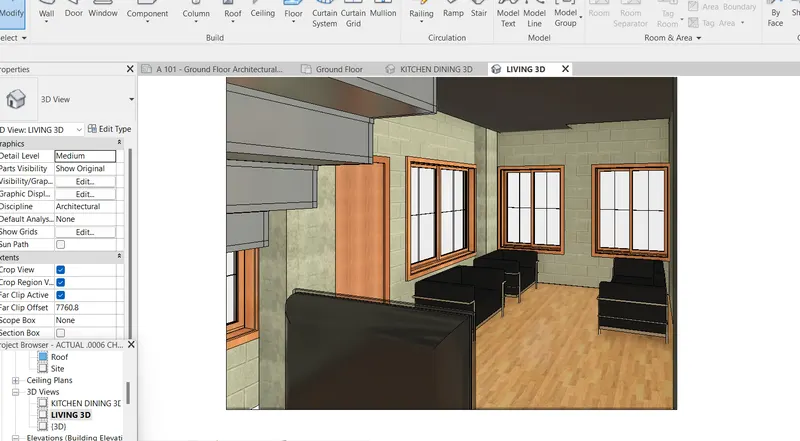
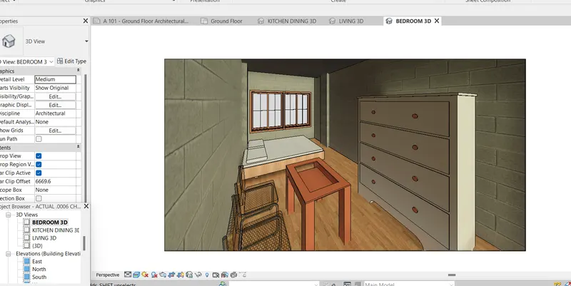
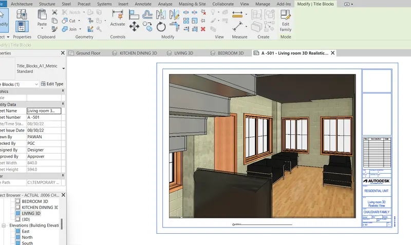
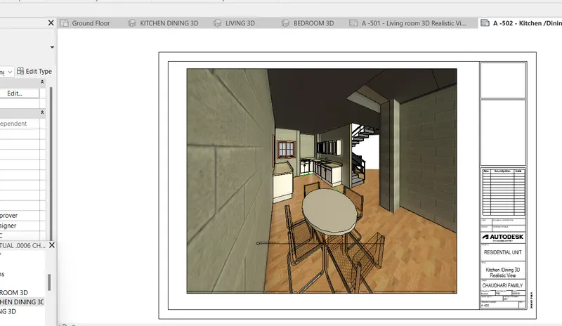
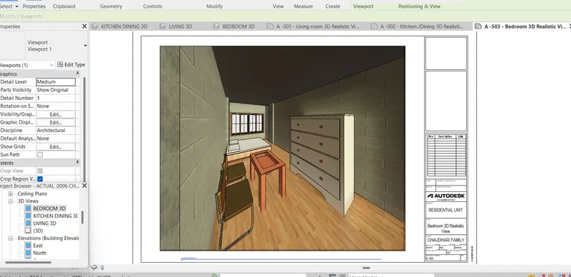
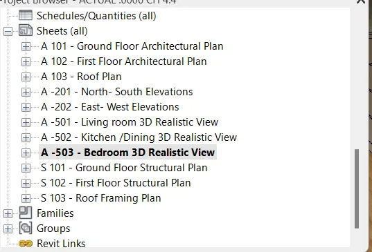
CONCLUSION: Thus we have created the 3D camera specific views for the Living room, Kitchen/Dining room and Bedroom and we have created sheets for the room views created with the name for the drawing sheet and numbering A-501, A 502, A 502 for the views which is seen in the project browser list.