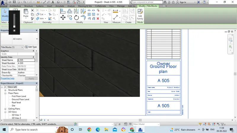
3D Creation of Celing, Roof, Architectural plan, Structural plan, Sectional view, Elevation view and Camera specific view for a house plan using REVIT
1. Aim: To create a model ceiling for the first floor from architecture tab above the walls at first floor level.
Introduction: To create a model ceiling for the first floor from architecture tab above the walls at first floor level.
Procedure:
- First we have to open revit software file for existing first floor plan.
- Now we have to create a ceiling for the first floor plan.
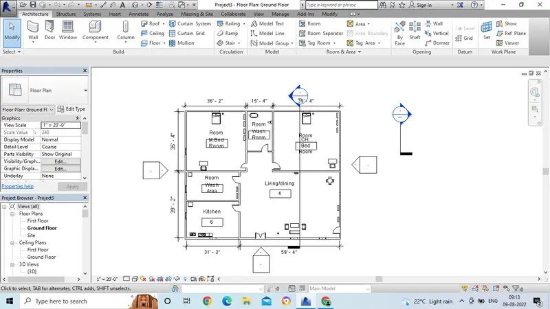
- For preparing ceiling for the first floor, go to ceiling command from the Architecture tab.
- Then go to sketch ceiling option.
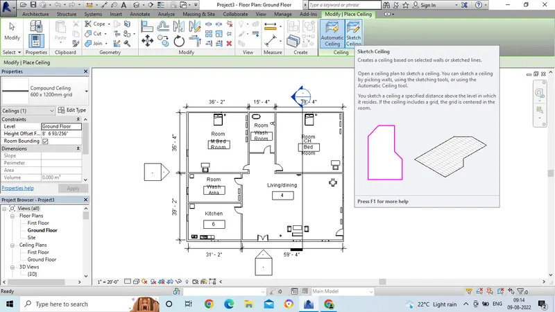
- Then the drawing command box will get open.
- From that select line or pick line option.
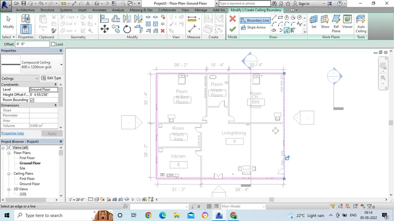
- Then draw the lines for the outer wall or select the outer line pick wall option.
- Then ceiling will be applied to the first floor level.
- To check the ceiling, go to 3d view option.
- Then we can see the ceiling option for the building.
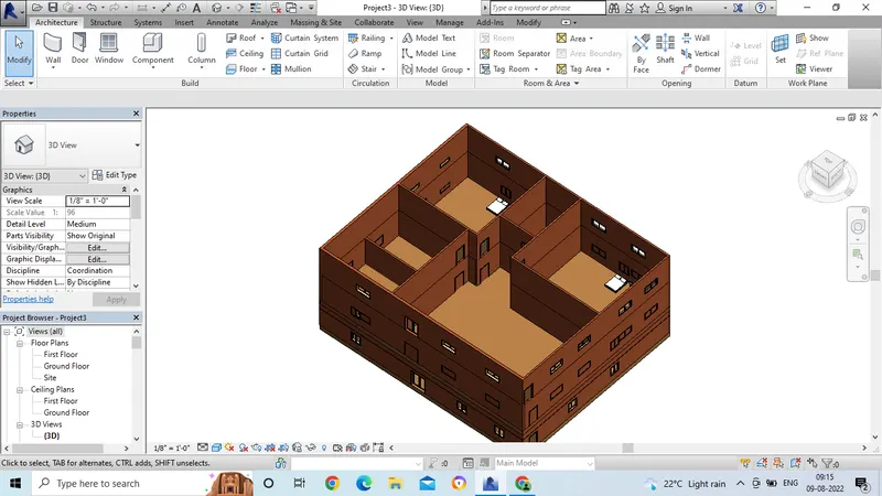
Result:
2. Aim: To model a roof above ceiling by selecting the footprints of the ceiling.
Introduction: To model a roof above ceiling by selecting the footprints of the ceiling by adjusting the toolbars appear on the screen adjust roof slope to 10deg.
Procedure:
- In this model, we have to create the roof plan for the building.
- Go to Architecture tab and select roof command.
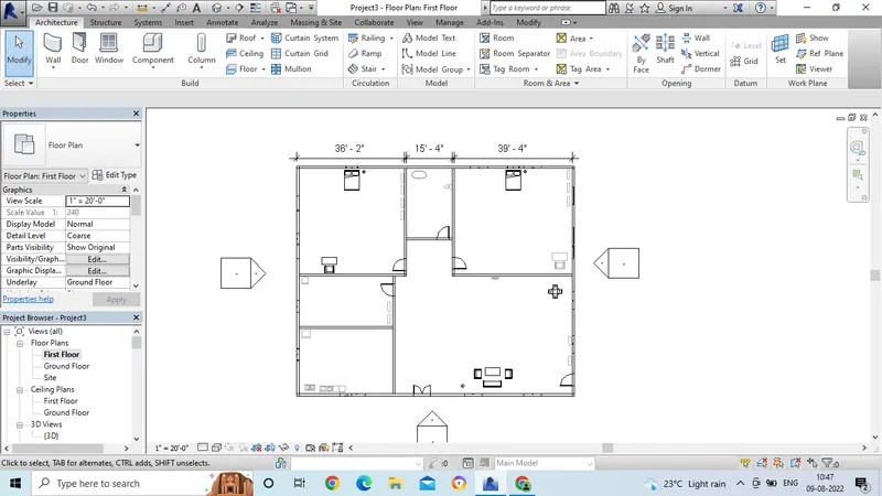
- From the roof command, then the draw command option will get open.
- From that, take line or pick line option.
- Then go to first floor plan in the properties browser option.
- Now take line or pick line option, then select the outer wall boundary option.
-
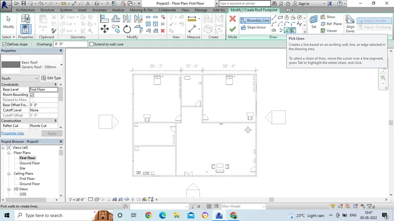
- Then the roof plan will get applied on the top of the floor.
- Now the top roof surface should be in 10degrees.
-
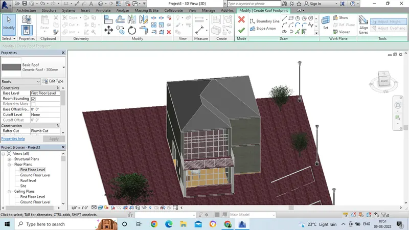
- Go to properties option, then select the scope option.
- Take 10deg for the roof top surface by selecting roof surface area.
- Then click on apply option.
- Now the roof top surface is changed to 10deg.
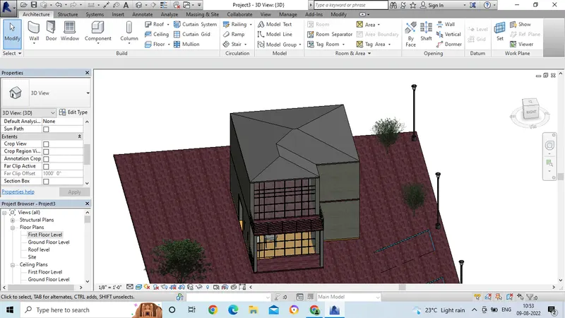
Result:
3. Aim: To save the file from week 2 to 4, create plan views for ground floor level and first floor including walls, floors and components.
Introduction: To save the file from week 2 to 4, create plan views for ground floor level and first floor including walls, floors and components.
Procedure:
- Open the revit file and take the drawing.
- Now go to the plan view option.
- For the architectural view, take the floor plan option.
-
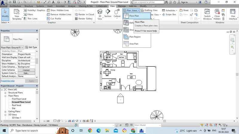
- Now architectural plan will get open.
- Then go to floor plan option in the project browser command.
-
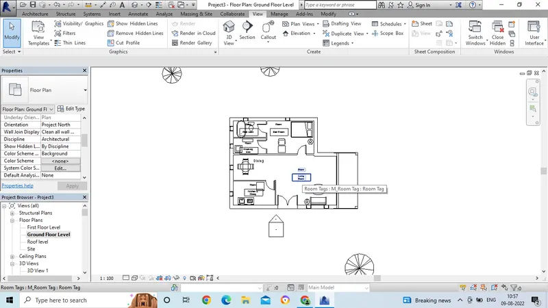
- Now for the structural plan view, go to the view option.
- Then select the plan view option and go for structural plan,
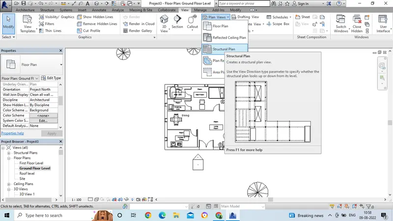
- Then the dialogue box will get opened.
- In that dialogue box, selct for the ground floor plan option.
- Then click on ok.
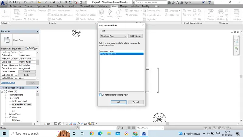
- Then the structural plan will get open.
- Go to the project browser option and select for the structural plan.
- Now click on the ground floor option, then the structural plan will get open.
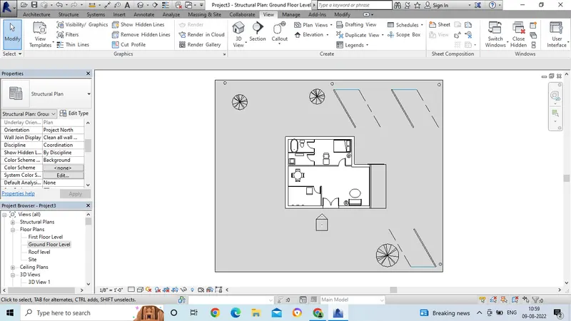
Result:
Architectural Plan view:
Structural Plan View:
4. Aim: To give the dimensions by using the tool bar in both Architectural drawing and in the structural drawing.
Introduction: To give the dimensions by using the tool bar in both Architectural drawing and in the structural drawing.
Procedure:
- Open the revit software and open the drawing with proper template.
- Now go to the ground floor plan and select the floor plan from the plan view option.
- Then go to the annotate tool bar and select the linear or aligned option for dimensioning.
- Then select the points properly end to end and we can get the dimension.
- In the same way give the dimensions for all the outer and inner walls.
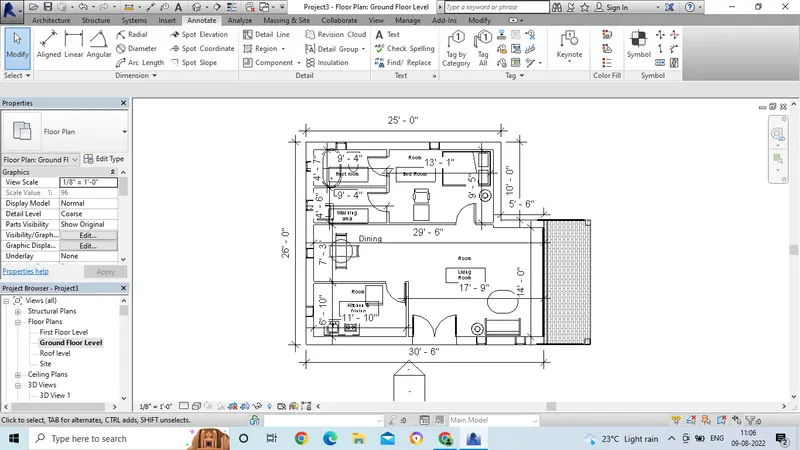
- Now take the structural floor plan from the plan view.
- In the same way, give the dimensions by selecting linear or aligned option.
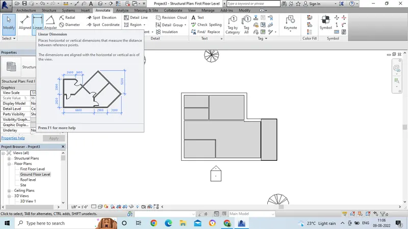
- Now go to the structural ground floor plan and select the floor plan from the plan view option.
- Then go to the annotate tool bar and select the linear or aligned option for dimensioning.
- Then select the points properly end to end and we can get the dimension.
- In the same way give the dimensions for all the outer and inner walls.
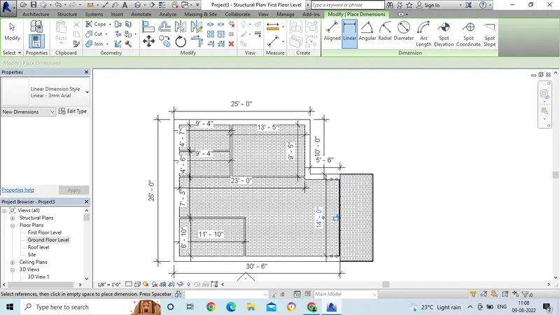
Result:
Architectural FLoor plan:
Structural Plan:
5. Aim: To create the sheet template from the view tab and adjust the parameters on the sheet to add appropriate views.
Introduction: To create the sheet template from the view tab and adjust the parameters on the sheet to add appropriate views.
Procedure:
- Open the revit software and open the drawing by using proper template.
- Then go to the view tool bar.
- Select the sheet command.
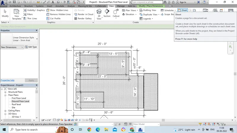
- Now select the paper size in which the drawing is to be placed.
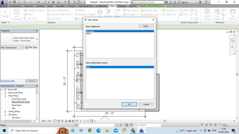
- Then the sheet will get opened.
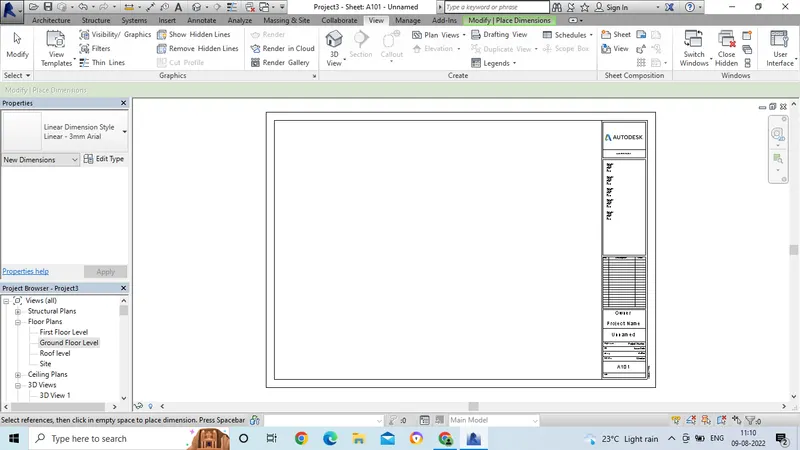
- Now change the information in the sheet by double click on it.
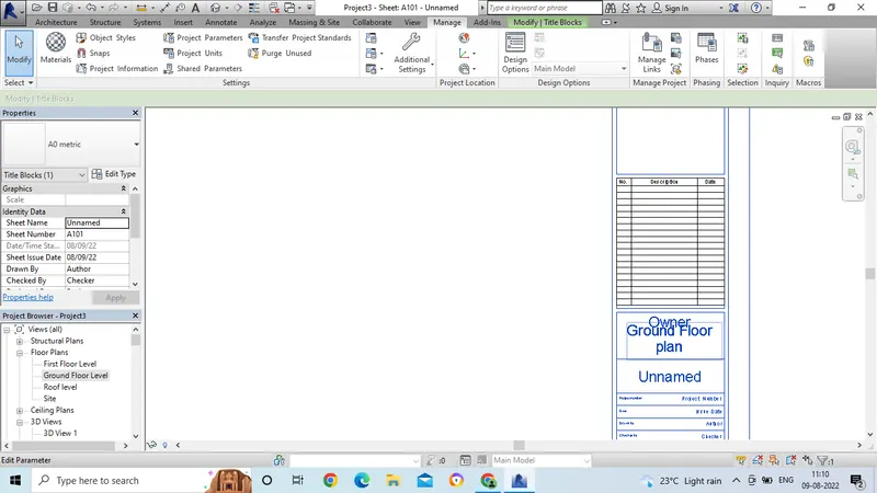
- We can edit the information in the sheet by using project information command.
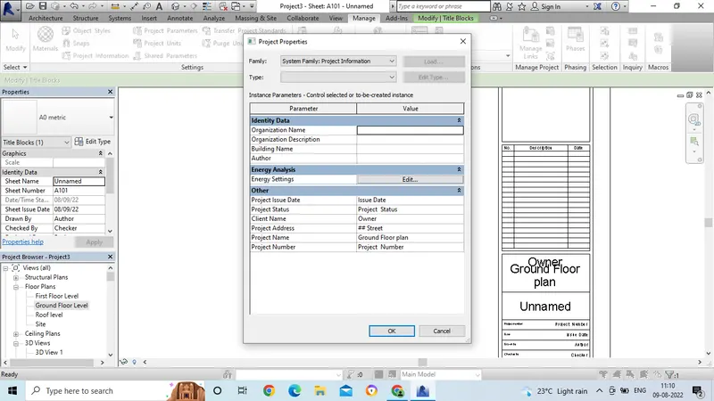
- Go to the manage tool bar and select the project information.
- Then the dialogue box will get open.
- In that dialogue box, we can give the information which is related to the drawing.
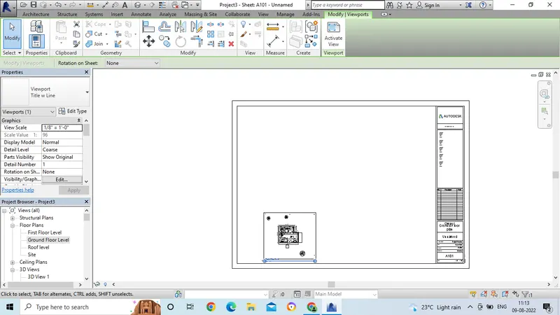
- Then place the drawing in the sheet by selecting from the project browser.
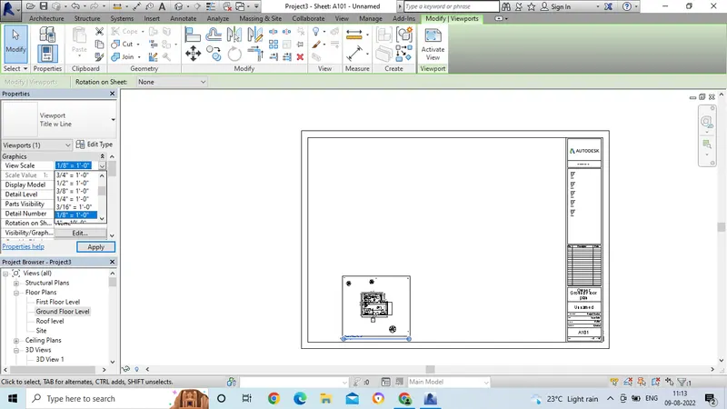
- Select the scale option in the properties bar, to adjust the drawing in the sheet.
- Now the drawing is adjusted in the sheet.
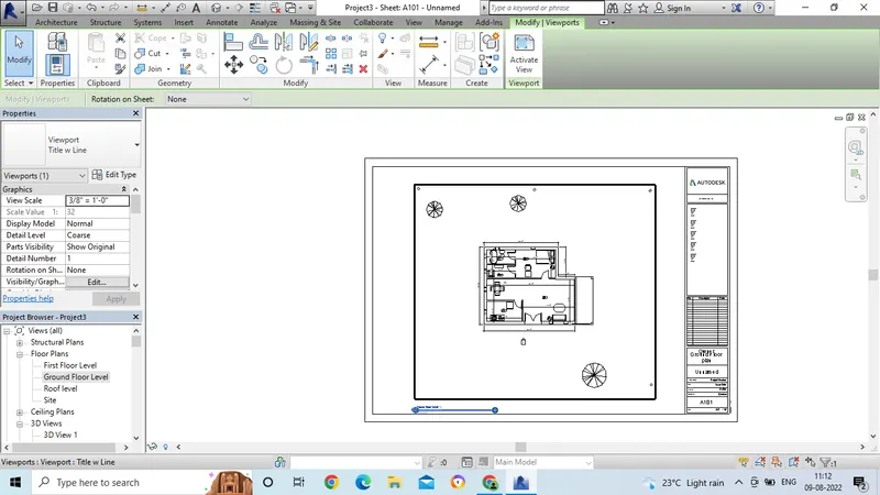
Result:
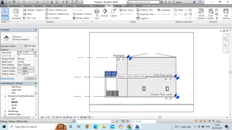
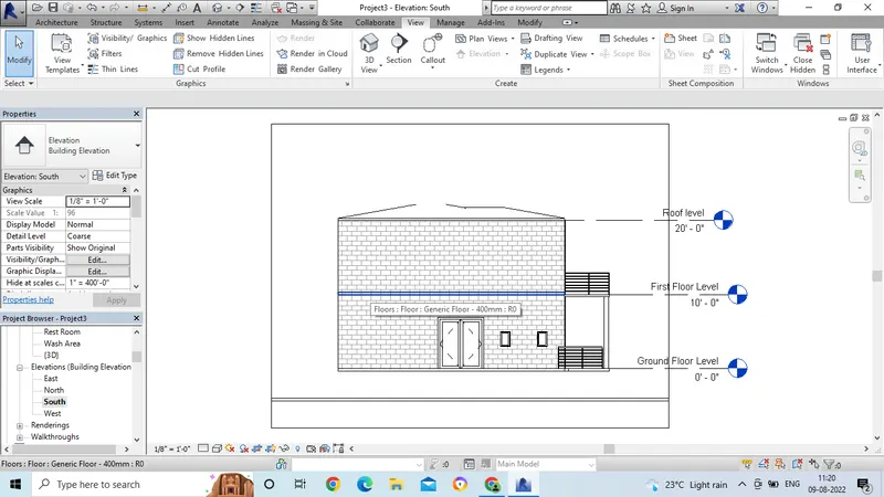
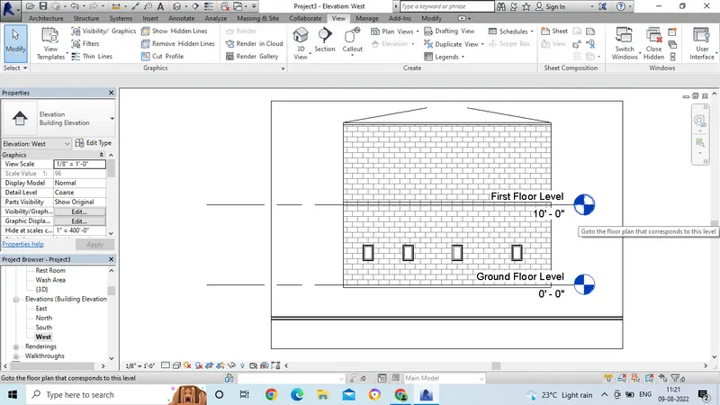
6. Aim: To create the elevation tab create the elevation views, looking at your building from East, North, South and West.
Introduction: To create the elevation tab create the elevation views, looking at your building from East, North, South and West.
Procedure:
- First we need to open the revit software and open the drawing.
- Then go to the view option.
- Now go to the elevation option and click on elevation.
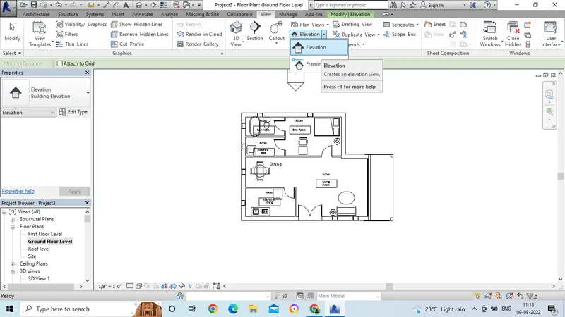
- Now we will see the point option.
- Click the point option on one side.
- Now in the project browser, we will see the elvation option.
- Then rename the elevation view as South.
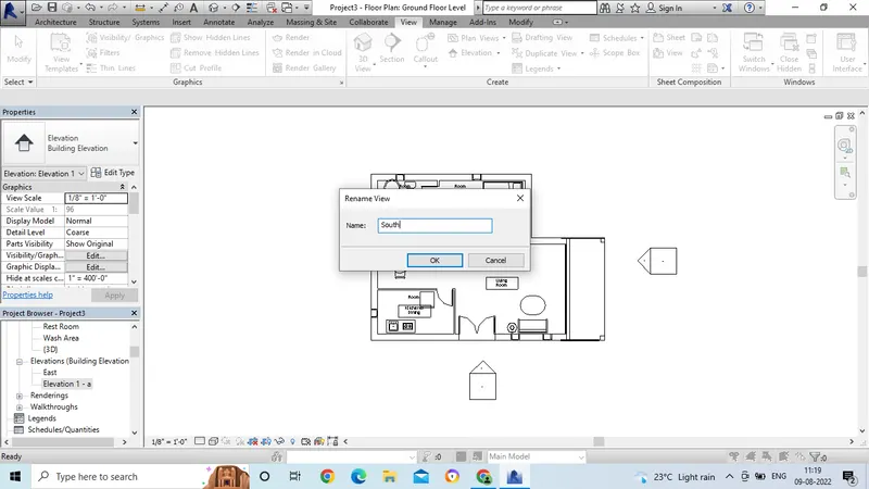
- In the same way, again click the point to the other side.
- And rename the view as East.
- Then after changing the name, double click on the elavation name option.
- then the elavation view will get opened.
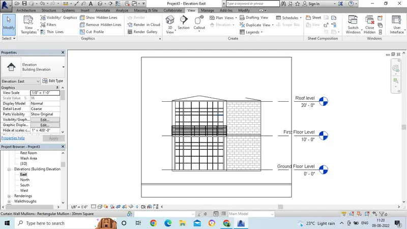
- Now for the North side elevation view option.
- Now for the south side elevation view option.
- Now for the West side elevation view option.
Result:
7. Aim: To produce a section cut through each room either cutting across longitudinally or in a transverse direction.
Introduction: To produce a section cut through each room either cutting across longitudinally or in a transverse direction.
Procedure:
- First we need to open the revit software and open the drawing by using the proper template.
- Then go to the view option.
- Next click on the section
- Then the section line will appear on the screen.
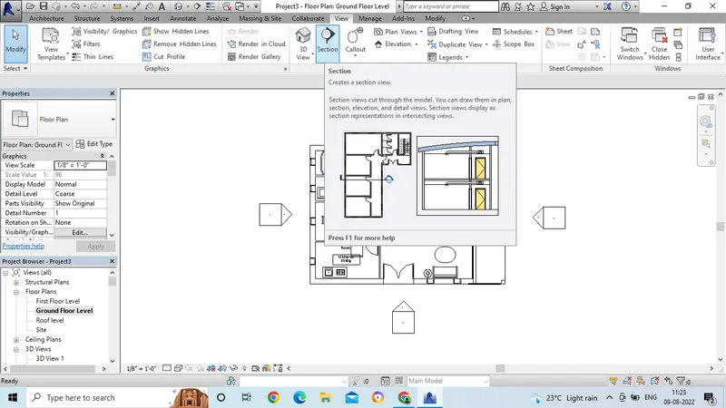
- Select the area in which area we need to show the section .
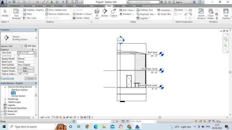
- In this view, we have taken the horizantal view section.
- And section is drawn in the horizantal view.
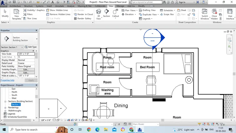
- After placing the section line, go to the section view in the project browser.
- Then select the section view and double click on the view.
- Then the section view will get appear.
- Click the right click for properties and rename the section name as Bed room view.
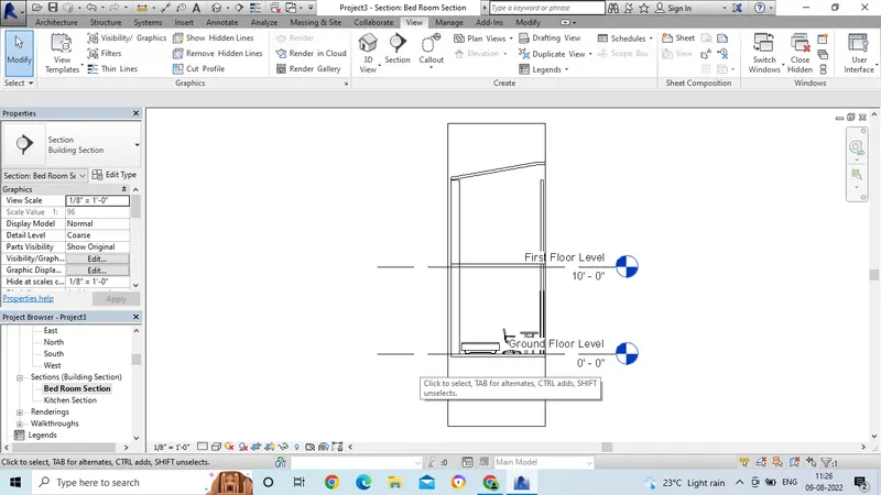
- In the same way, after selecting the section, then draw the tranverse direction line.
- And again go to the section view, and rename as kitchen.
-
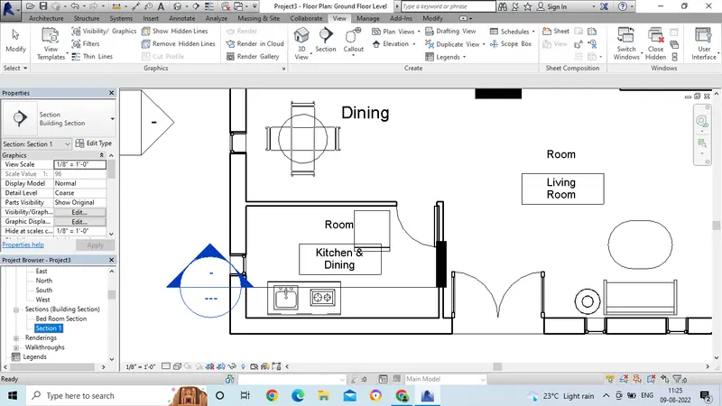
- Now kitchen section view is ready,
- Double click on the name and the section view will get opened.
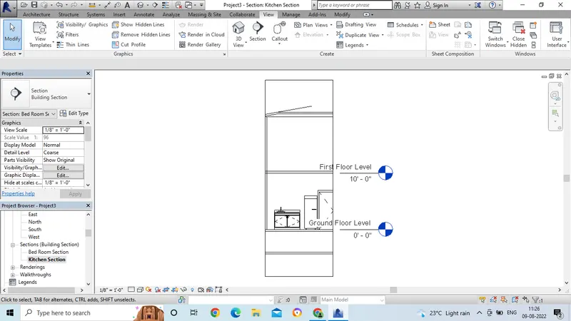
- In the same way, again take the section line for the living area.
- Go to the project browser and rename the section name.
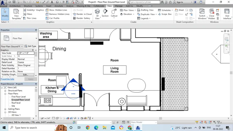
- Then the section view is ready for living area.
Result:
8. Aim: To classify the view for plan, section and elevation views to either design or documenstation category using property browser.
Introduction: To classify the view for plan, section and elevation views to either design or documentation category using property browser.
Procedure:
- Open the revit software and open the drawing with proper template.
- Go to the view option and click on the section view.
- Now take the section lines horizantal and transverse view.
- Now we have the project browser.
- select the section view in the project browser.
- In the project browser we have the many view options.
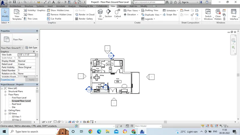
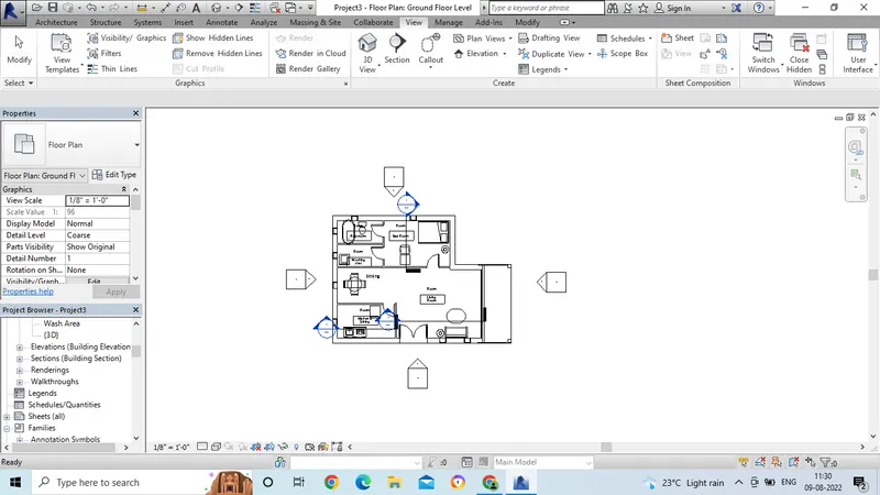
- Now drag to the down portion in the project browser.
- We can have many views and option in the project browser.
Result:
9. Aim: To create the sheet template produced create multiple sheets as in the given attachment.
Introduction: To create the sheet template produced create multiple sheets as in the given attachment.
Procedure:
- Open the revit software and open the drawing by using proper template.
- Then for creating the sheet first we need to select the view direction.
- Go to the view option and click on the floor plan.
- Then select the sheet option in the view command bar.
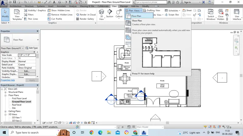
- There we can see the dialogue box to select the sheet size.
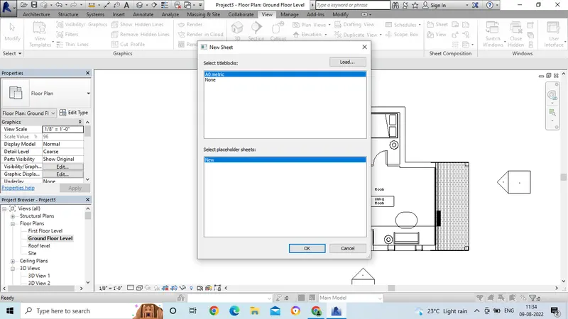
- Then the sheet will get open.
- And select the ground floor plan from the project browser.
- Then drag that in to the sheet .
- Now from the properties option, select the scale to adjust the plan in the sheet.
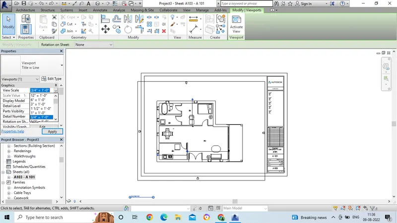
- Now we can see the sheet in the project browser.
- Now click on the sheet and right click on the floor.
- Then we can change the name as ground floor plan.
- Or we can doble click on the sheet to edit the name.
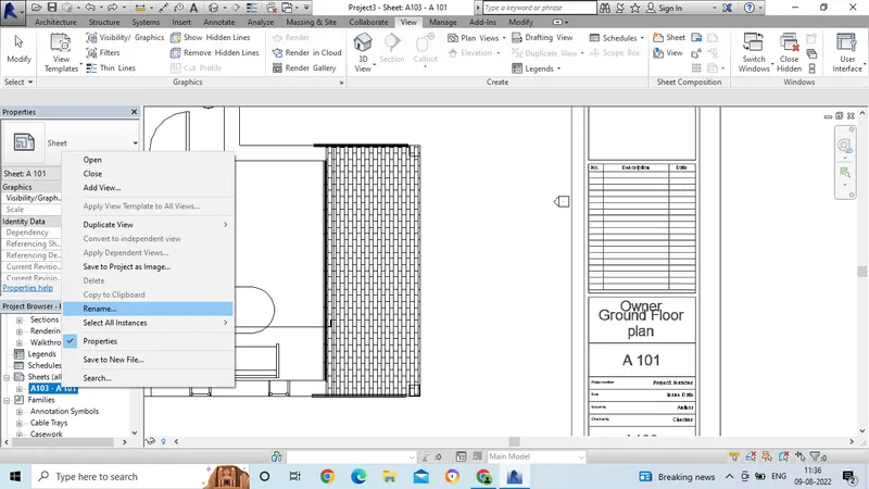
- Now the name has been changed in the project browser and in the sheet.
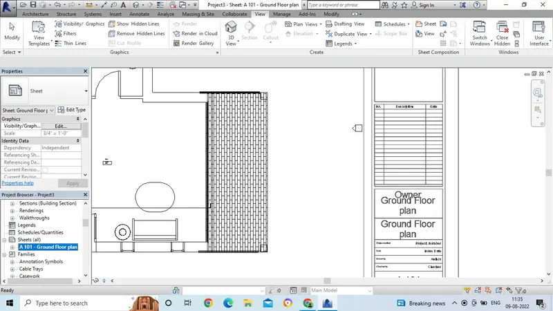
- In the same way, select for the first floor plan.
- Select the sheet from the view command bar.
- Then drag the floor plan to the sheet.
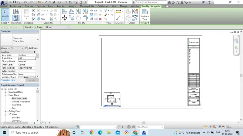
- Then click on the proper scale to adjust the drawing in the sheet.
- Go to the project browser and change the name as First floor plan.
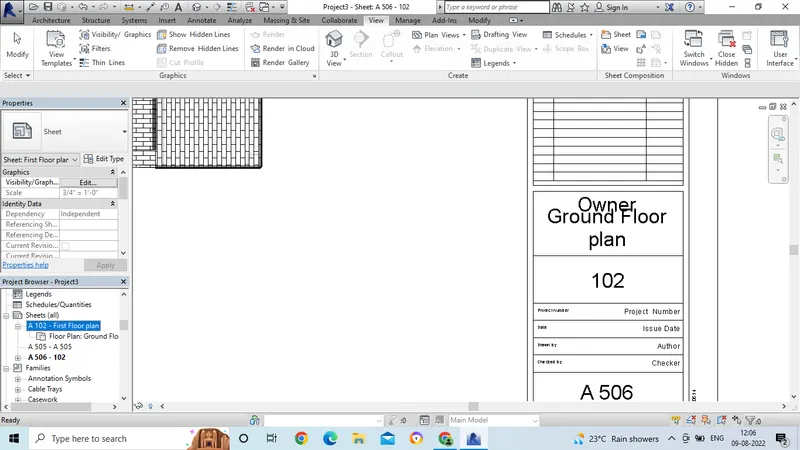
- In the same way, select for the roof level.
- Select the proper sheet size.
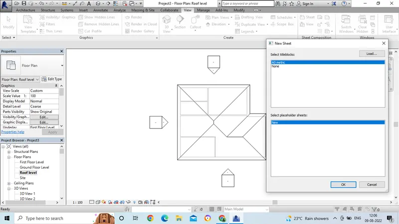
- Now select the drawig and adjust in the sheet with proper scale option.
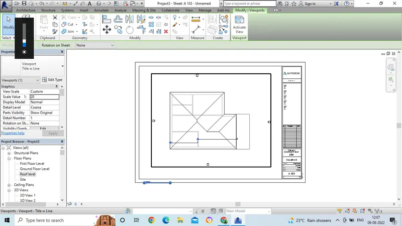
- Now change the name in the project browser or by cediting in the sheet.
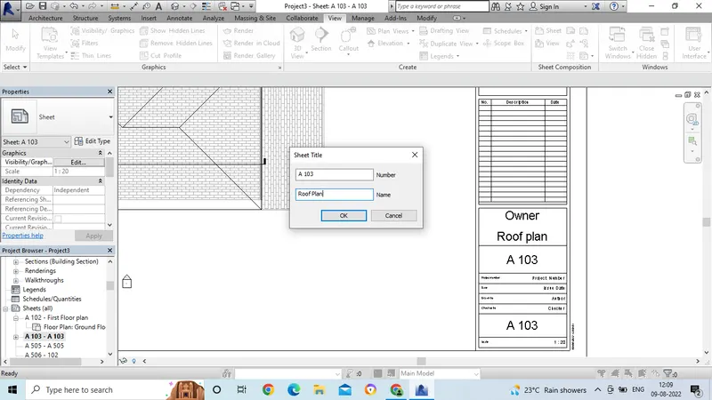
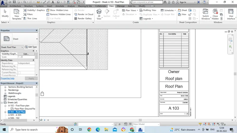
- Now the name is changed to the Roof plan as in the given attachment.
- Now we have to do in the same way for the structural plan.
- Go to the view option and select the plan view for structural plan.
- Now select the sheet and select the drawing form the structural plan in the project browser.
- Adjust the drawing in the sheet with proper scale alignment.
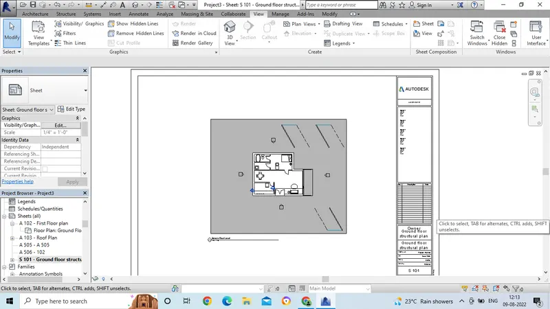
- In the same select structural plan for the first floor plan.
- From the plan view, we have to select the structural plan option.
- And now the procedure is same for the sheet selection and adjusting the drawing in the sheet.
- Now we can see in the structural view for the first floor plan.
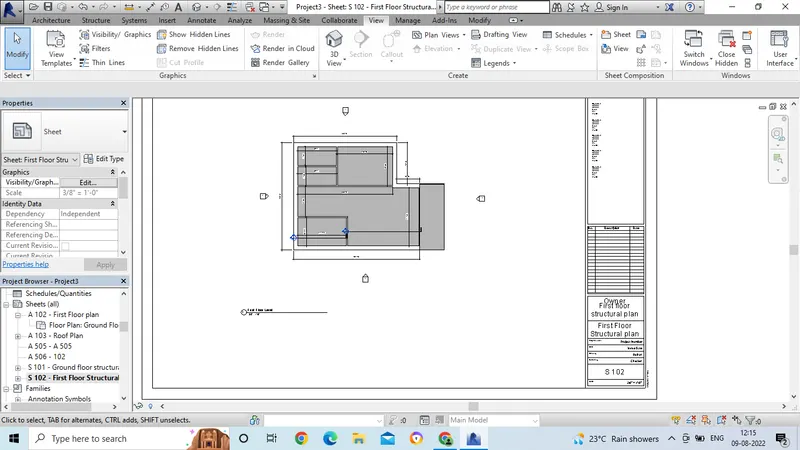
- In the same way, do for the roof framing also.
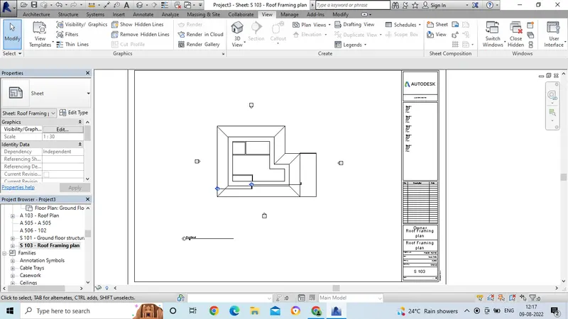
- Now we have to insert elevation view in the sheet.
- For that go to the elevation view in the project browser.
- And adjust the view in the sheet.
- Now change the name in the porject browser by using properties.
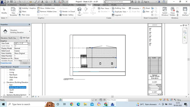
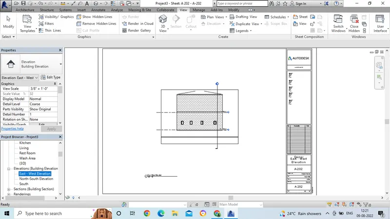
- In the same go for the another elevation option.
- And rename as the East-West elevation view.
Result:
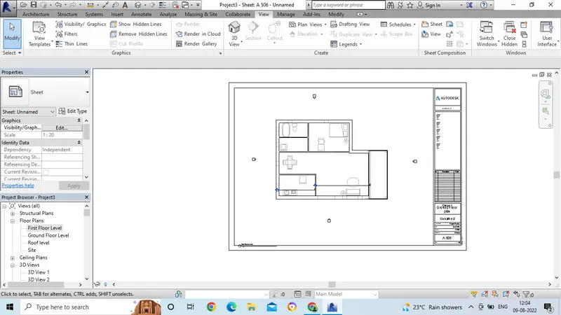
Architectural plan:
Structural plan:
Roof plan:
Elevation view:
10. Aim: To create the camera-specific view or a 3D view in each room based on the views create a new set of sheets to place 3D views.
Introduction: To create the camera-specific view or a 3D view in each room based on the views create a new set of sheets to place 3D views.
Procedure:
- Open the revit software and open the drawing by using proper template.
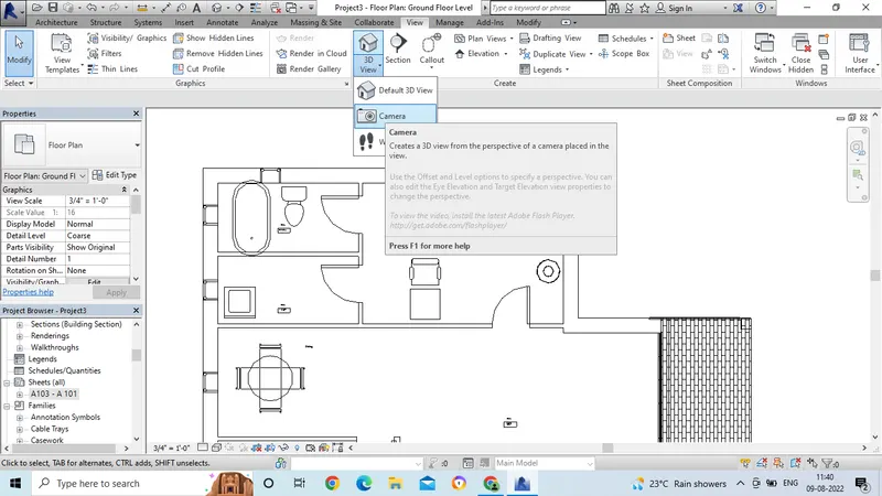
- Then for creating the camera view go the view option.
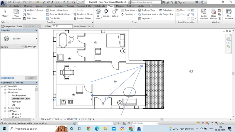
- In that select 3d view, and select the camera option.
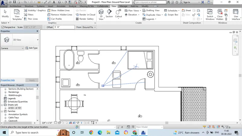
- Now place the camera in which we want to view.
-
- Then after placing the camera we can see the camera lense liness which are passing in the room.
- Now select the view from the project browser.
- And adjust the lines of the camera view.
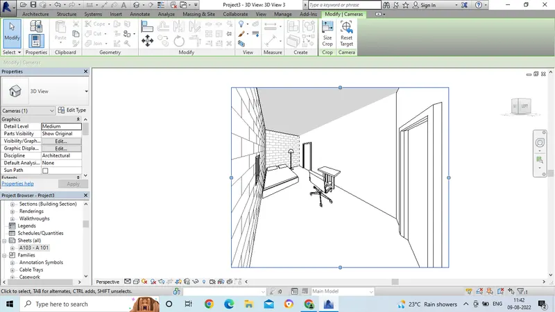
- For clear view select the realistic option.
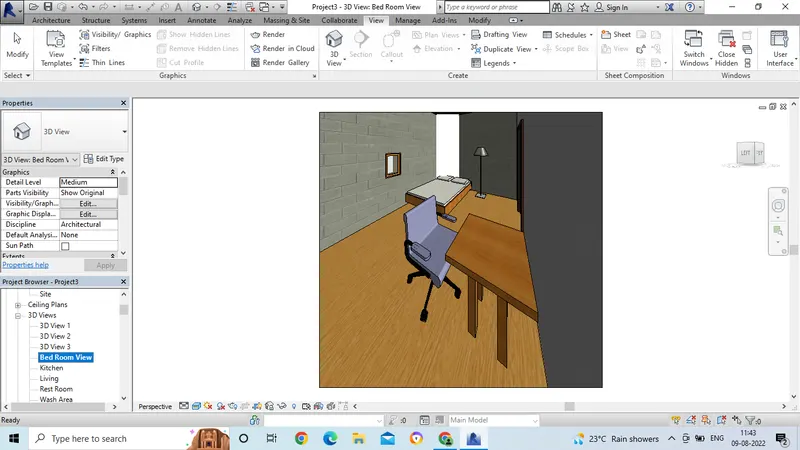
- Now the fnal 3D view is ready for bed room.
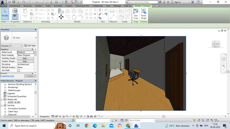
- Select the view and change the name in the project browser as Bed room view.
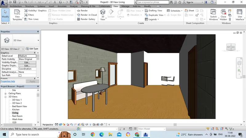
- In the same way, now the camera view is applied to living room.
- We can see the living room area in 3d view.
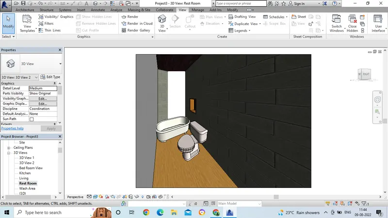
- In the same way, Now the camera view is applied to Rest room.
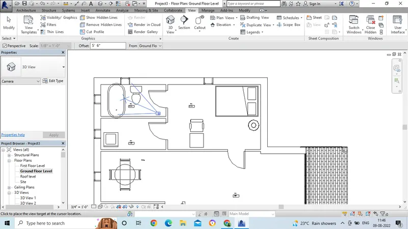
- We can see the 3D view of the Rest room area.
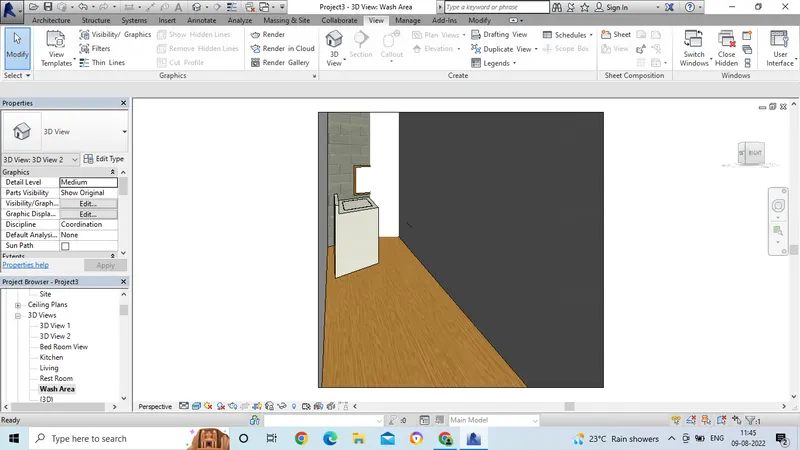
- In the same way, now the camera view is applied to wash area.
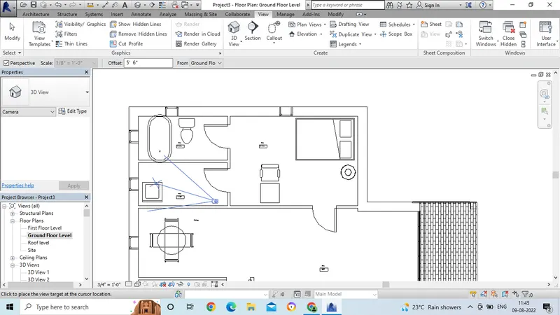
- Now we can see the 3D view of wash area.
- After creating the views, we have to place the view in the sheets.
- Select the sheet in the view option.
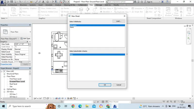
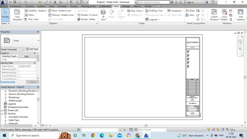
- Now the sheet will get open.
- Now we have to place the 3d view which we have created, we have to place in the sheet.
- Select the view from the project browser and drag in to the sheet.
- Adjust the view range and ajust the scale and insert the drawin in the sheet.
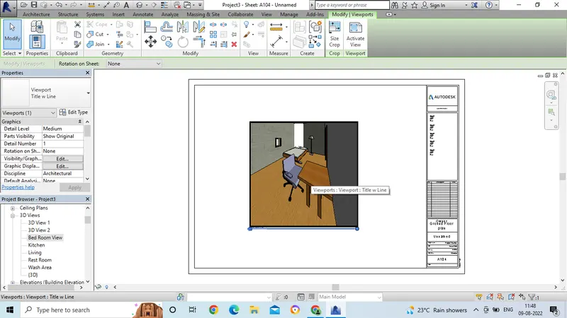
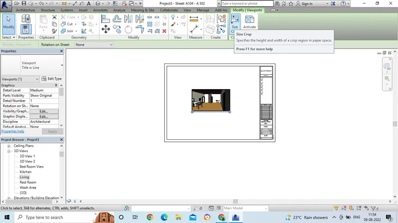
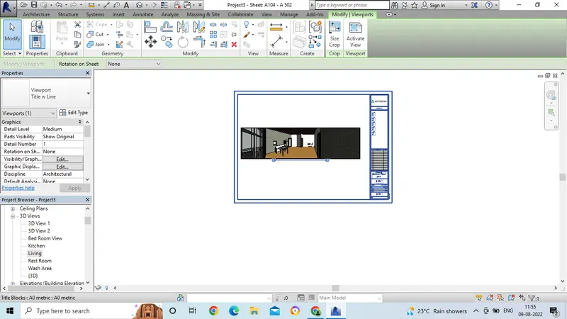
- Now to adjust the image, select the size crop option in the modify tool bar.
- And adjust the scale to the drawing.
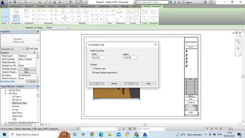
- Now we can see the image after adjusting the image withe proper scale.
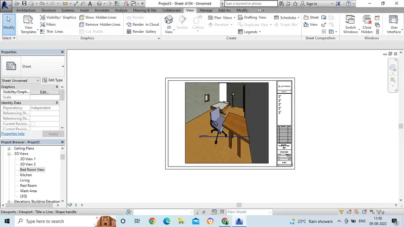
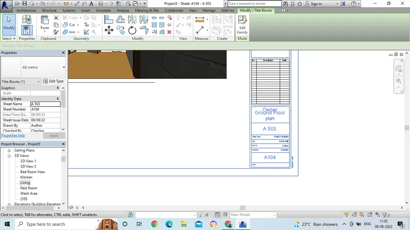
- Now change the name in the sheet or in the proejct browser as in the given attachment.
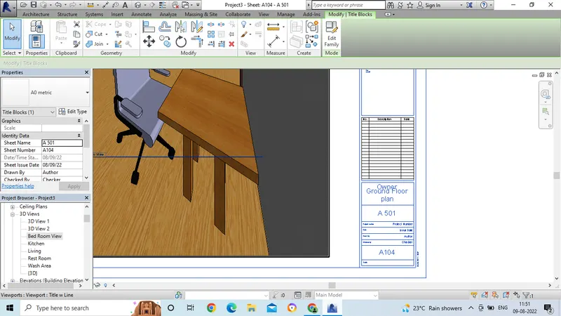
- Now place the kitchen view to the sheet in the same way.
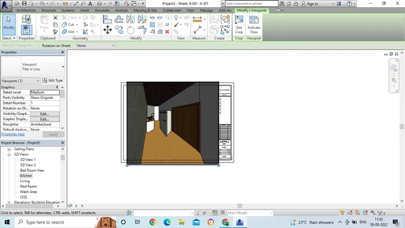
- And change the name to the kitchen which is given in the attachment.
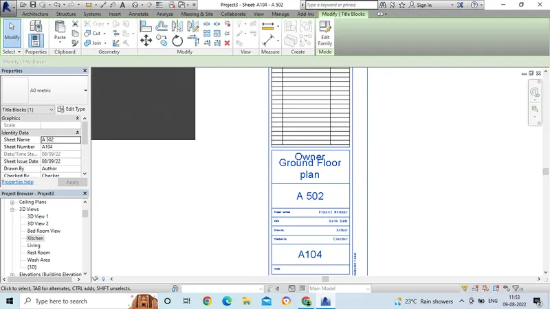
- Now place the Living area view to the sheet in the same way.
- And change the name to the Living area which is given in the attachment.
 x
x
- Now place the Living area view to the sheet in the same way
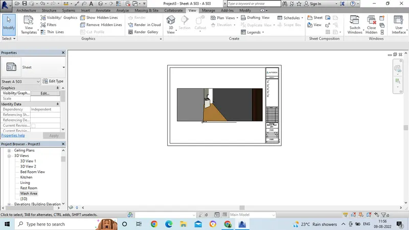
- And change the name to the Living area which is given in the attachment.
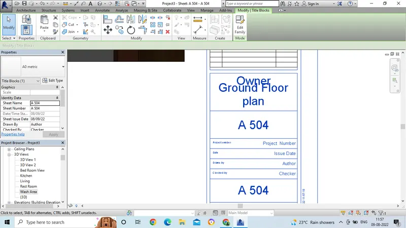
- Now place the Rest room area view to the sheet in the same way
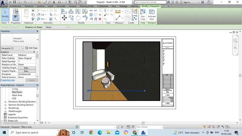
- And change the name to the Rest room area which is given in the attachment.