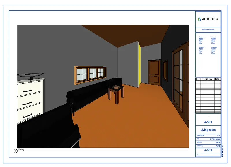
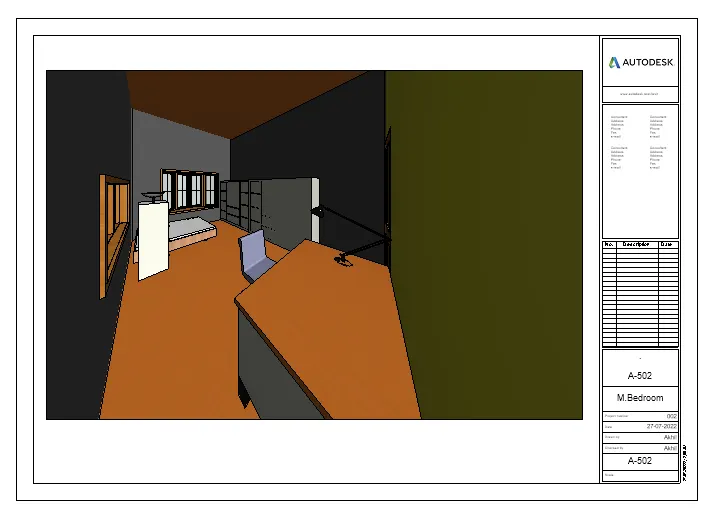
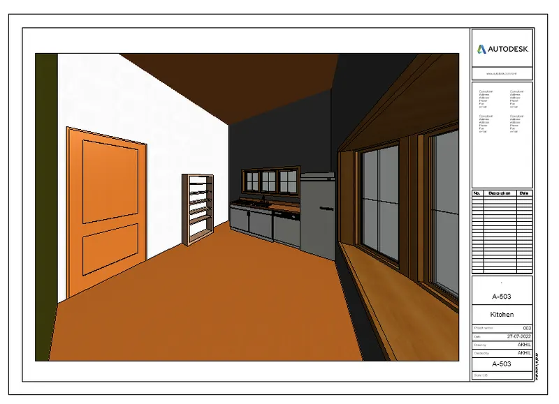
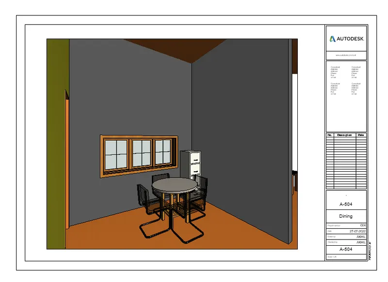
3D Creation of Celing, Roof, Architectural plan, Structural plan, Sectional view, Elevation view and Camera specific view for a house plan using REVIT
1) AIM: To use the drawing from week 3 and apply the celing to it.
PROCEDURE:
- Go to desktop and select the below shown icon.
- Once the icon the selected then the below shown dialogue box will appear.
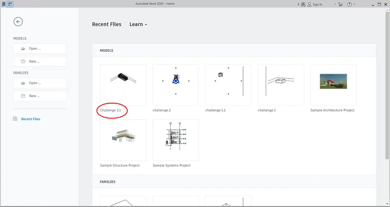
- There in the model option there will be saved week 3 challenge drawing and select that then the revit drawing screen will appear with the selected drawing.
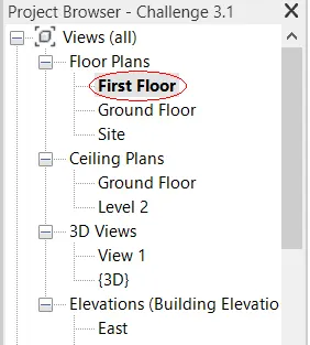
- Once you go to the drawing screen then make sure that you are in first floor view or level 2. Go to project browser and there in floor plans select or double click on the first floor option.
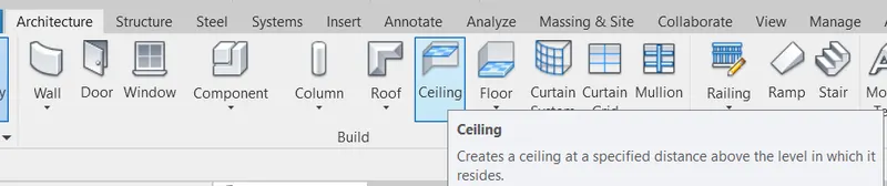
- Then go to architectural option and there select the Celling option.
- Once the celing option is select the we are directed in to modify option with the below shown set of options.

- There it will be auto selected to AUTOMATIC CEILING but here we are not using that selection method so select the SKETCH CEILING option.
- Once that option is selected then again we are directe in to another set of options with different settings and that are similar to that of floor selections.

- Once the above selection set are visible then select the method you want to selet the ceiling boundary.
- Here we can either choose the pick line method or draw a line where ever the slab is needed.
- Here i have selected pick line method and the result are below shown. Select the outer wall lines so that the whole building is covered.
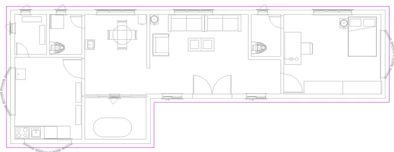

- Here we can define the offest of the slab or length of slab that has to be come out of outer side of wall can be defined.
- After doing all teh selection remember the lines should be closed like it should connect one another.
- Then click the green tick mark that is present in the options and the slab is ready.
- Then if needed we can also chnage the materials of the slab as done for walls and floor.
RESULT:
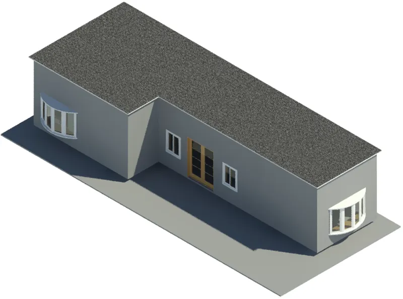
2) AIM: To create a roof by selecting the footprints of the ceiling. Then to make slope as 10 degree using adjustment toolbars.
PROCEDURE:
- Go to desktop and select the below shown icon.
- Once the icon the selected then the below shown dialogue box will appear.
- Here click NEW option which is present in upper left hand side.
- The above dialogue option will appear.
- Here select the template file and type of project and click OK button.
- Then the drawing sheet will appear with different options to draw and with certain levels.
- Once the drawing sheet is opened now we have to save the drawing.
- Save the drawing using the mentioned steps in previous question.
- Go to architectural toolbar and select wall there are two types of wall.
- Load bearing and Architectural wall select as wanted.
- Select the required type of wall and different options will appear in the toolbar.
- Using those options we can do several editings in wall and different shapes also.
- Here in draw option we can draw the wall in different shapes and size.
- Here we will choose ine option to draw a wall.
- Here we have to select the height of wall.
- Alignment of wall in Location line. Offset if any needed.
- After selecting all the dimensions and doing all the editings now draw the line as required.
- Click anywhere in the drawing sheet and take the curzer horizontally and type 45' the wall will be displayed as shown.
- Now take the cursor in 90degree and type the reading or length as mentioned.
- Carry the same steps and complete the wall in four sides.
- After completing the outer wall then we have to draw the inside partition wall for that we can use either offset command or just draw using line.
- If you need the floor and celling can be done.
- The text are added using the text option in the Annotate option.
- After creating the walls of required shape and size now as the question we have to do a roof.
- Go to architecture option there select ROOF option.
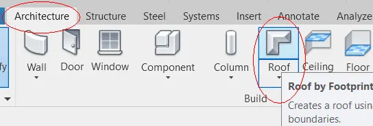
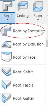
- Once the roof is selected then we have to select the method and type of roof.
- A drop menu will appear with several options select the required one.
- Now a modify oprions will be shown in the menu as same for ceiling and floor options.
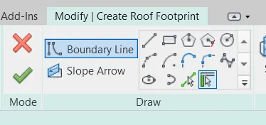
- Here we will select pick lines option and select the outer lines of all the walls.
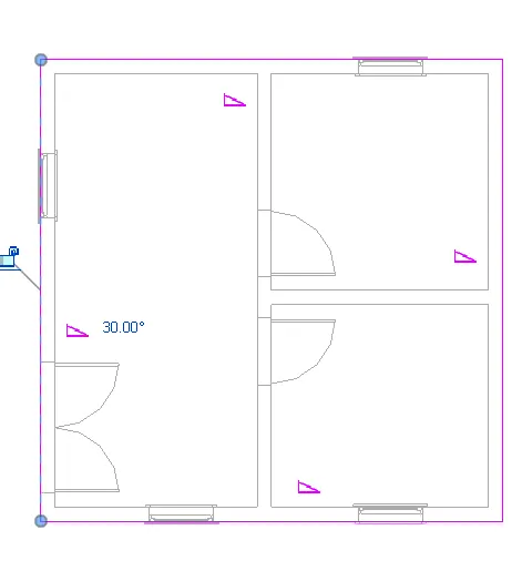
- It will be seen as shown above.
- Then click the green tick mark in the options and the roof will be created.
- Then go to 3D view too see the roof accurately.
- Then select the roof that has been created before.
- Then in the left hand side of screen there will be property option there scroll down till dimension.
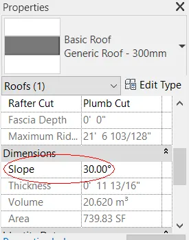
- There will be a option as SLOPE select that and remove the previous slope angle.
- Now we have to type the angle we want.
- If there are any unit problem in the angle option then type UN and a below shown dialogue box will appear.
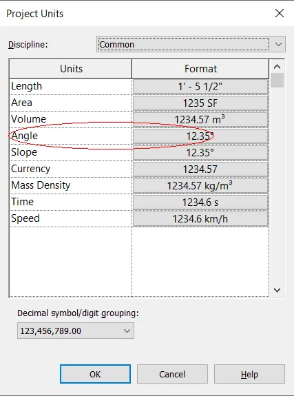
- There select the Angle and make it to degree.
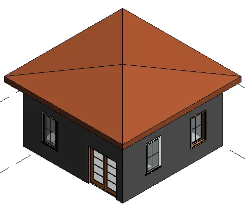
- By this way we can draw a sloped roof and edit it's slope angle.
RESULT:
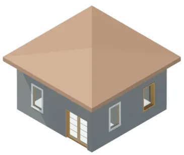
3) AIM: To create plan views for ground floor level and first-floor level including all the walls, floors, and components. Separate them to architecture and structural plans.
PROCEDURE:
- Go to desktop and select the below shown icon.
- Once the icon the selected then the below shown dialogue box will appear.
- There in the model option there will be saved week 3 challenge drawing and select that then the revit drawing screen will appear with the selected drawing.
- Then go to VIEW option in show panel.
- The option dialogue tab will appear there go to PLAN VIEWS.

- Then a dialogue box will appear with the several options.
- Here we first do the ARCHITECTURAL PLAN so select floor plan.
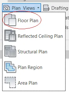
- Once we select the floor plan a next shown dialogue box will appear.
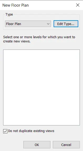
- If needed do the required settings in the EDIT TYPE option.
- After all the ettings select the option ok.
- The architectural plan will appear in the drawing sheet screen.
- Once the architectural plan is obtained then follow the same steps and in the last select structural plan instead of floor plan.
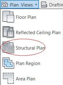
- After selecting the structural plan option the below showned dialogue box will appear.
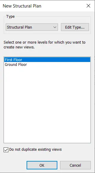
- Here we have to select the neede level of plan with respect to that selection we will get the drawing in the sheet.
- By this method we can get the different types of plan.
RESULT:
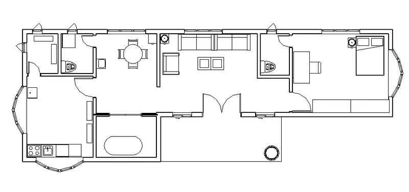
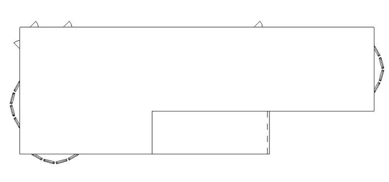
Ground floor architectural plan:
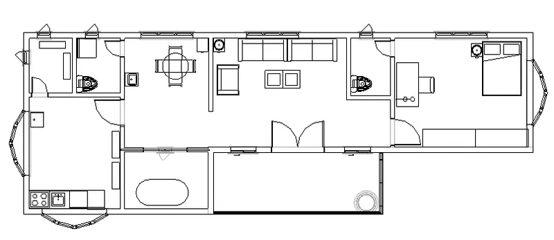
First floor architectural plan:
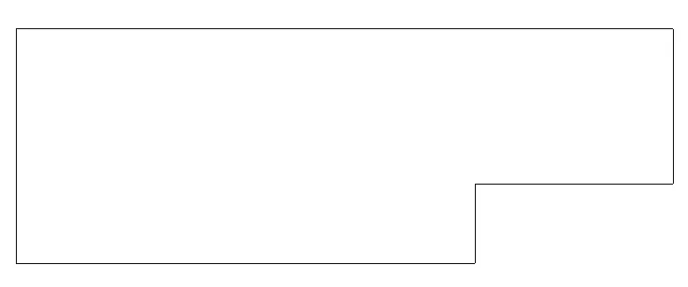
Ground floor structural plan:
First floor structural plan:
4) AIM: To add the dimensions for the Architectural and Structural plan.
PROCEDRE:
- First we create the Architectural and Structural plans.
- Go to desktop and select the below shown icon.
- Once the icon the selected then the below shown dialogue box will appear.
- There in the model option there will be saved week 3 challenge drawing and select that then the revit drawing screen will appear with the selected drawing.
- Then go to VIEW option in show panel.
- The option dialogue tab will appear there go to PLAN VIEWS.
- Then a dialogue box will appear with the several options.
- Here we first do the ARCHITECTURAL PLAN so select floor plan.
- Once we select the floor plan a next shown dialogue box will appear.
- If needed do the required settings in the EDIT TYPE option.
- After all the ettings select the option ok.
- The architectural plan will appear in the drawing sheet screen.
- Once the architectural plan is obtained then follow the same steps and in the last select structural plan instead of floor plan.
- After selecting the structural plan option the below showned dialogue box will appear.
- Here we have to select the neede level of plan with respect to that selection we will get the drawing in the sheet.
- After completing the creation of plans now we will start with dimensioning of the plans.
- Go to Annotate tab and the below mentioned toolbar will appear.
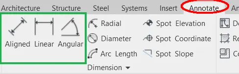
- Now here select the type of dimensioning you want.
- Here there are several options for dimensioning. Here we can do the dimensioning of radius, Diameter etc.
- Now here we are selecting the LINEAR dimensioning because the drawing is aligned linerally.
- Now go near drawing and click the start point of the dimension.
- Next click on the other side of the drawing which is in right angle.

- After that take the curser in upward direction till the required height then place it.
- Cary the same steps for all the remaning side of the wall.
- Here we can use either Aligned or Linear dimensioning.
- Do the same for different plans.
- We can switch between plans in the Project Browser menu.
RESULT:
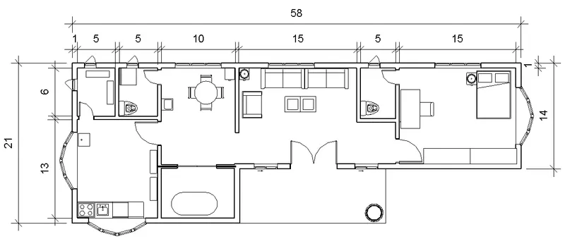
Architectural Drawing plan dimensions:
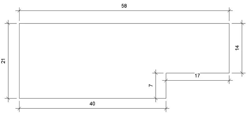
Structural Drawing plan dimensions:
5) AIM: To create a sheet template from the view tab and adjust the parameters on the sheet to add appropriate views.
PROCEDURE:
- Go to desktop and select the below shown icon.
- Once the icon the selected then the below shown dialogue box will appear.
- There in the model option there will be saved week 3 challenge drawing and select that then the revit drawing screen will appear with the selected drawing.
- Now we have to create the sheet as mentioned in the question
- So go to view option in task bar and select the sheet option

- Once you click the sheet option then the below shown dialogue box will appear
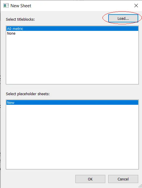
- Once the above box appears now we have to load the sheet we required.
- So press the load option and follow the below steps.
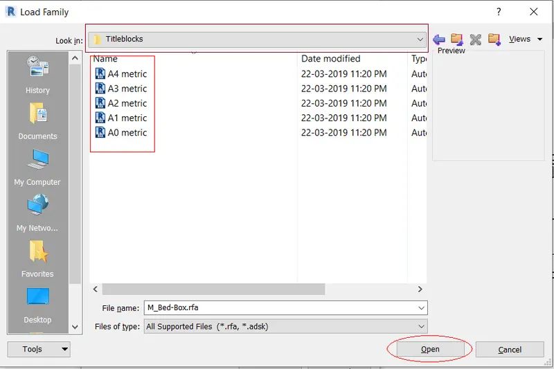
- The above box will appear as soon as we select the load option.
- Here we have to go to the source of sheet like the place where the template are stored.
- Once we go to the designated place now we have have to select the type of sheet required for our drawing.
- Once we have got the required sheet then press open.
- It will be loaded to the New sheet box.
- Once the drawing sheet is visible in the new sheet dialogue box then press okay.
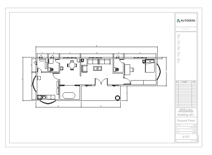
- The selected sheet will appear in the screen.
- Now we have to drag the required view to the sheet from Project Browser.
- After draging the drawing into the sheet set the view scale in teh properties menu.
- Make the drawing fits the sheet properly.
- Carry the same procedure for al the other required drawing sheets.
RESULT:
6) AIM: To create the elevation views of the building from East, North, South, and West.
PROCEDURE:
- Go to desktop and select the below shown icon.
- Once the icon the selected then the dialogue box will appear from there open the perviously drawn drawing
- In the normal case the East, North, South, and West direction views are already given.
- It will be present in the elevation opyion in the Project browser tool box.
- If in case the elevation view got deleted then we should use the below shown steps to create the elevation views.
- Go to view option in the tool bar and select the elevation option present there.

- The another drop options will appear in that in that select the elevation option.
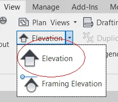
- Then below shown icon will come with the mouse cursor.
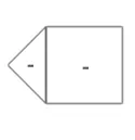
- Place it in the required direction and required place.
- After placing in all the four side now do the naming as required.
- By this way the elevation view is created.
- The final view of the direction icon is showed in the result below.
RESULT:
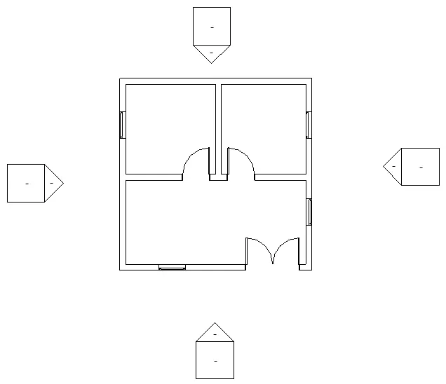
7) AIM: To create a section cut through each room either cutting across longitudinally or in a transverse direction.
PROCEDURE:
- Go to desktop and select the below shown icon.
- Once the icon the selected then the dialogue box will appear from there open the perviously drawn drawing.
- Then go to View option in the toolbar there will be a option called Section select that.

- After selecting the section option the we are back to drawing sheet.
- Remember the drawing should be in Ground floor plan view.
- Then draw the section line either horizontally or vertically as you wish in the required room.
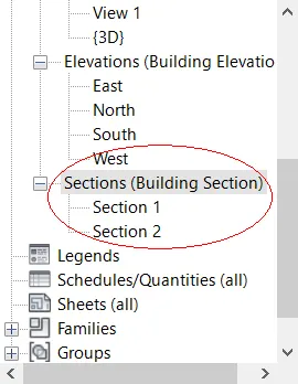
- As soon as the section lines are drawned then a view will be created in the Sections group.
- Now rename it as needed with respect to your convinent.
- The section can be increased or decreased in the view place. Using the solid circle option as highlighted below.
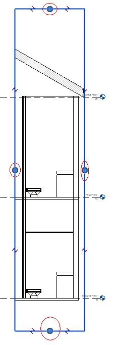
- By these steps the section can be accurately done.
RESULT:
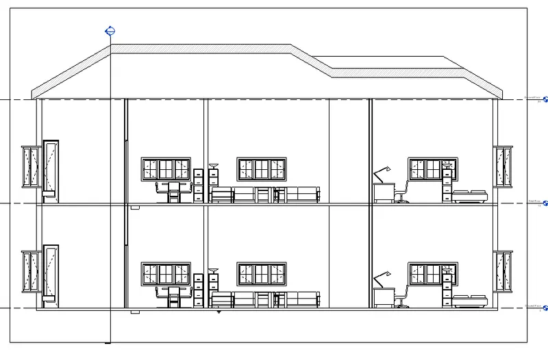
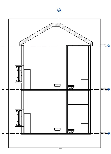
8) AIM: To classify the Plan Views, Section Views and Elevation views either to Design or Documentation category using Properties browser.
PROCEDURE:
- Go to desktop and select the below shown icon.
- Once the icon the selected then the dialogue box will appear from there open the perviously drawn drawing.
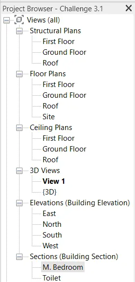
- Here the all views are created for a same drawing in the all previously answered questions.
- Here we only have to show the set of views in the Project browser.
- As the view we create it will be visible in respective ctagoery in project browser.
- To create all the we can refer the steps of previous question.
RESULT:
9) AIM: Using the sheet template produced multiple sheets as mentioned.
PROCEDURE:
- Go to desktop and select the below shown icon.
- Once the icon the selected then the below shown dialogue box will appear.
- There in the model option there will be saved week 3 challenge drawing and select that then the revit drawing screen will appear with the selected drawing.
- Now we have to create the sheet as mentioned in the question
- So go to view option in task bar and select the sheet option
- Once you click the sheet option then the below shown dialogue box will appear
- Once the above box appears now we have to load the sheet we required.
- So press the load option and follow the below steps.
- The above box will appear as soon as we select the load option.
- Here we have to go to the source of sheet like the place where the template are stored.
- Once we go to the designated place now we have have to select the type of sheet required for our drawing.
- Once we have got the required sheet then press open.
- It will be loaded to the New sheet box.
- Once the drawing sheet is visible in the new sheet dialogue box then press okay.
- The selected sheet will appear in the screen.
- Now we have to drag the required view to the sheet from Project Browser.
- After draging the drawing into the sheet set the view scale in teh properties menu.
- Make the drawing fits the sheet properly.
- Carry the same procedure for ail the other mentioned drawing sheets with given names.
RESULT:
a)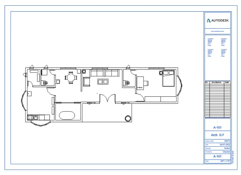
b)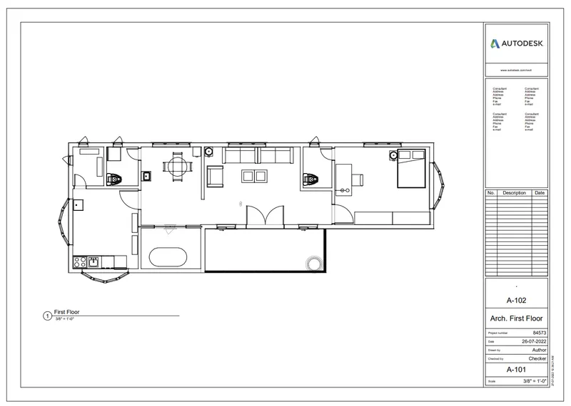
c)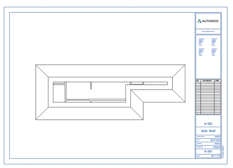
d) 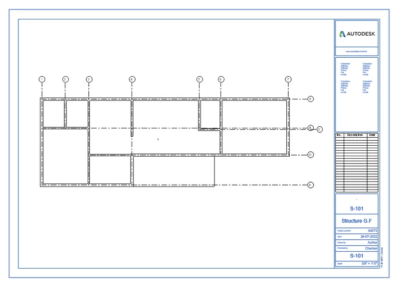
e) 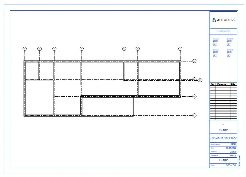
f)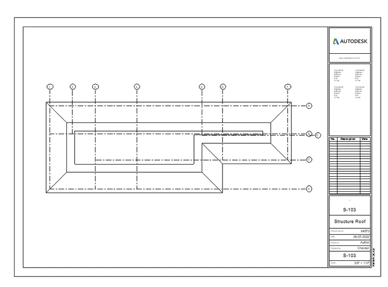
g) 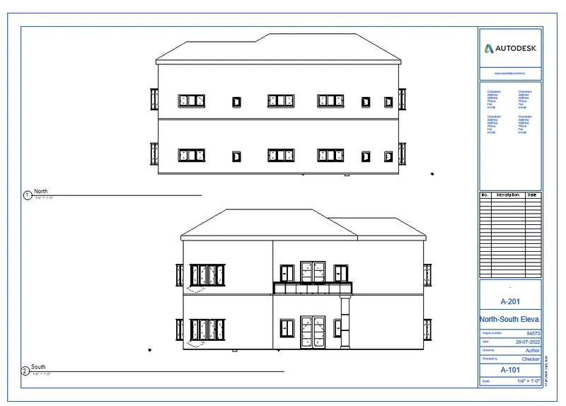
h) 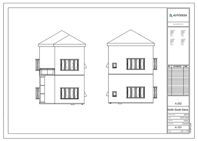
10) AIM: To create a camera-specific view in each room and plot it using template sheet.
PROCEDURE:
- Go to desktop and select the below shown icon.
- Once the icon the selected then the below shown dialogue box will appear.
- There in the model option there will be saved week 3 challenge drawing and select that then the revit drawing screen will appear with the selected drawing.
- Now we have to place the camera in each room so go to view command in the toolbar.
- Then go to 3D view and there a drop menu will appear then go to camera there.
-
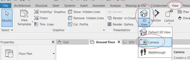
- Then select the place where the camera has to be placed.
- Now there will be 3 lines take that lines to where the camera has to focus or cover.
- Click on the point or place where the camera has to be faced.
- As soon as the cameras are placed the new views will appear in the 3D views.
- Now we have to create the sheet as mentioned in the question
- So go to view option in task bar and select the sheet option
- Once you click the sheet option then the below shown dialogue box will appear
- Once the above box appears now we have to load the sheet we required.
- So press the load option and follow the below steps.
- The dialogue box will appear as soon as we select the load option.
- Here we have to go to the source of sheet like the place where the template are stored.
- Once we go to the designated place now we have have to select the type of sheet required for our drawing.
- Once we have got the required sheet then press open.
- It will be loaded to the New sheet box.
- Once the drawing sheet is visible in the new sheet dialogue box then press okay.
- The selected sheet will appear in the screen.
- Now we have to drag the required view to the sheet from Project Browser.
- Here to change the size of ratio of the drawing we have to select the drawing and a Size crop option will appear in the option box.
- A new dialogue box will appear and there we have to select the scale option and apply the required scale value.
- Carry the same procedure for ail the other mentioned drawing sheets with given names.
RESULT: