3D Creation of Celing, Roof, Architectural plan, Structural plan, Sectional view, Elevation view and Camera specific view for a house plan using REVIT
1Q]
AIM: -
Create a Ceiling for the model drawn
Assign material to the ceiling
Change the thickness properties to the ceiling
PROCEDURE: -
Open the Revit Software.
Open the File in which we created the Floor plan.
Select ARCHITECTURE tab
Go to BUILD panel and choose Ceiling tool

In Modify Ceiling tab choose Sketch Ceiling
In Modify/Create Ceiling Boundary tab, Go to Draw panel
Choose Pick Line option and select the outer lines of the wall.

After selecting all the boundary lines, click on Finish Edit mode.
In Properties Browser edit the constraints
Level- Ground Floor
Height offset from level- 10’
Click on Apply.
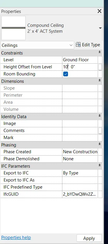
In Properties Browser, select Edit Type
Type Properties dialogue box opens
Click on Duplicate
Change Name: - 2’x 4’ ACT SYSTEM-Ceiling 6”
Select parameter STRUCTURE and click on edit
Change the thickness to 6” units.
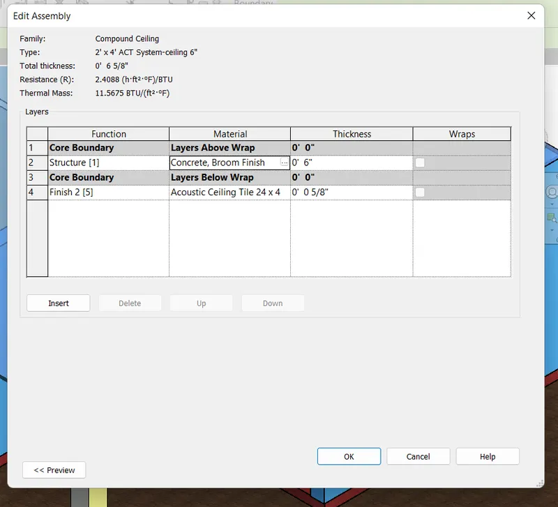
Under Material click on the 3 dots symbol
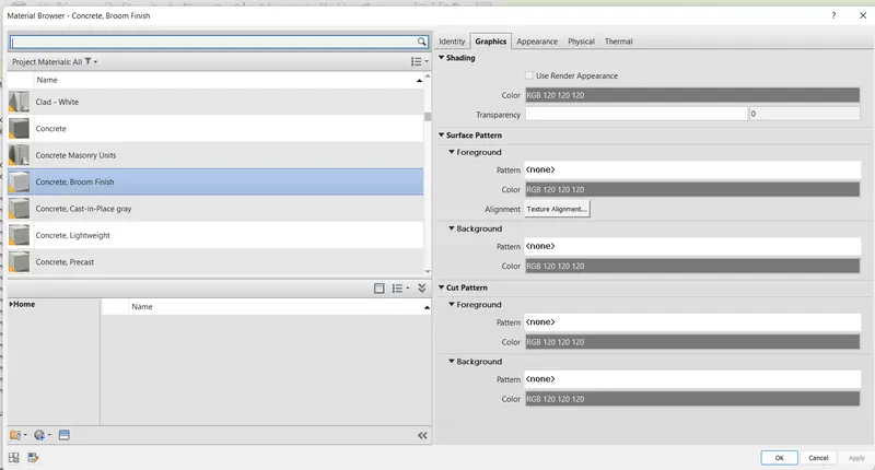
Material Browser dialogue box opens
Select the material: Concrete broom Finish
Press OK.
Click Apply in the Type Properties dialogue box.
Selected material is assigned to the Floor.
Press OK.
RESULT: -
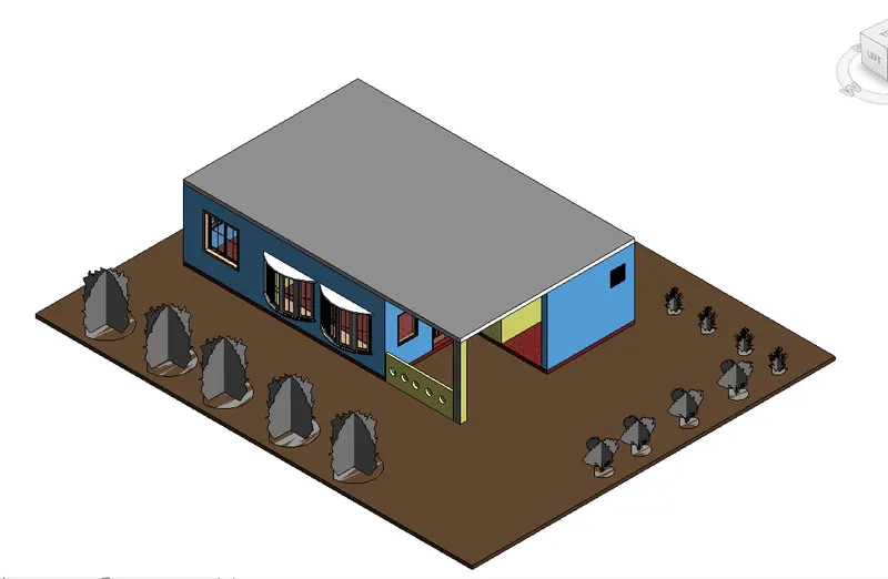
We created Ceiling to the model
We changed the thickness properties of the Ceiling.
We assigned material to the ceiling.
2Q]
AIM: -
Create roof of model by selecting the footprints of the ceiling.
Edit the Roof slope to 10 degrees.
Assign material to the roof.
PROCEDURE: -
Select ARCHITECTURE tab
Go to DATUM panel and choose Level tool
Provide level of 10’ units and mark the level as Roof
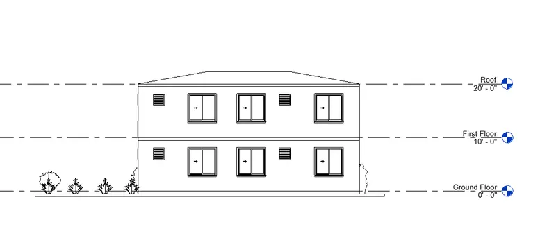
Select ARCHITECTURE tab
Go to BUILD panel and choose Roof tool
Choose ROOF BY FOOTPRINT option
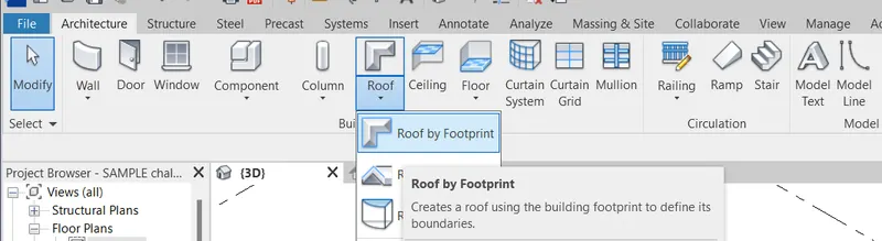
In Modify/create Roof footprint tab, go to Draw panel
Select pick line option and click on the outer edges of the ceiling on all sides.
Click on Finish edit mode.

In Properties Browser, edit the properties
Change the Base level to ROOF
Click Apply
In Properties Browser, select Edit Type
Type Properties dialogue box opens
Click on Duplicate
Change Name: - Generic Roof-6”
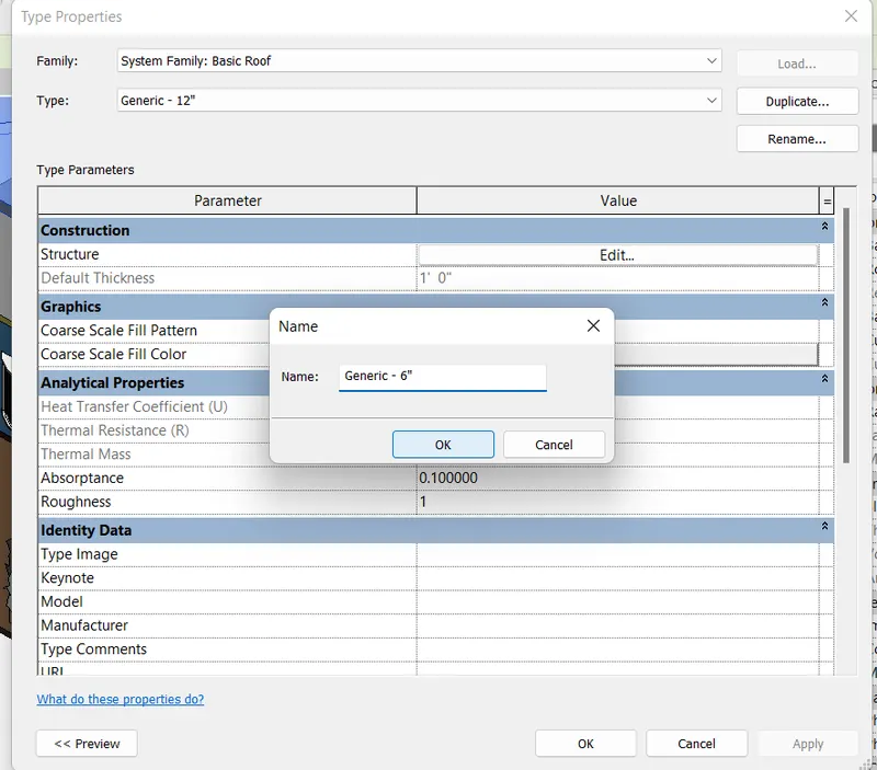
Select parameter STRUCTURE and click on edit
Change the thickness to 6” units.
Under Material click on the 3 dots symbol
Material Browser dialogue box opens
Select the material: Default mass Exterior
Press OK.
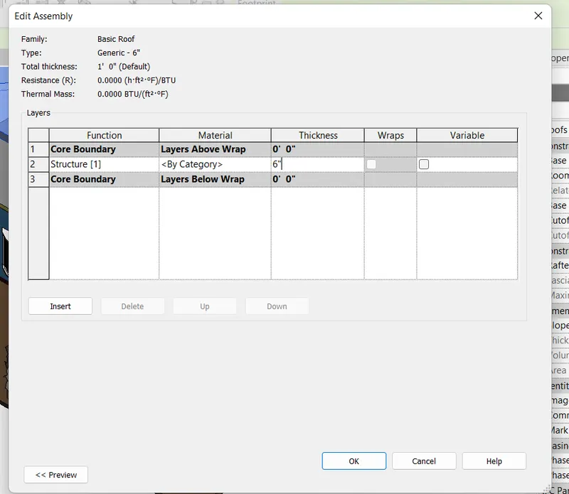
Click Apply in the Type Properties dialogue box.
Selected material is assigned to the Floor.
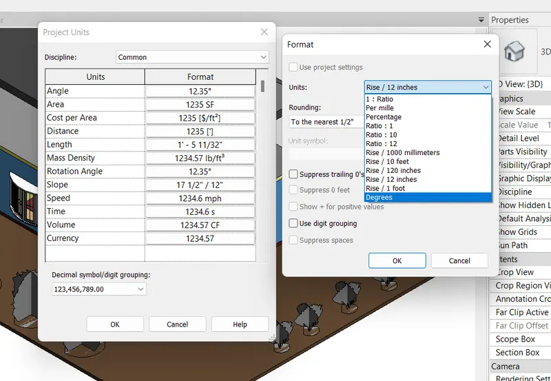
Select MANAGE TAB
Go to SETTINGS panel, Choose Project Units
Change the Slope units to Degrees
Press OK
Select the ROOF in the model space
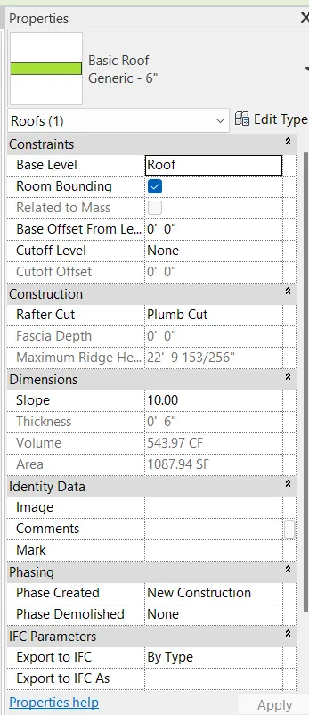
In Properties Browser, edit the Slope value.
Change the slope value to 10 degrees
Press APPLY
RESULT: -
Created associated level to create the Roof
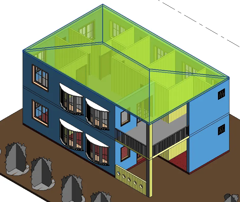
We created roof of model by selecting the footprints of the ceiling.
Edited the Roof slope to 10 degrees.
Assigned material to the roof.
3Q]
AIM: -
Create plan views for ground floor level and first-floor level including all the walls, floors, and components.
Separate them to architecture and structural plans
Architecture plan must have walls, floors, and all the components placed within the building
Structure plan must have details of only walls, floors, and columns
PROCEDURE: -
In the PROJECT BROWSER
Go to Floor Plans and select Ground Floor
Select the VIEW TAB
Go to Create panel and select Plan views tool
Choose Floor plan from the dropdown list

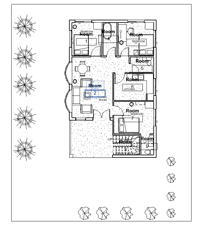
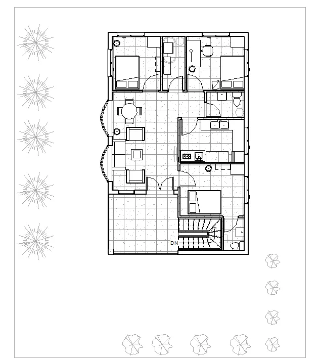
Architectural Plan view for the Ground Floor is created
In the PROJECT BROWSER
Go to Floor Plans and select First Floor
Select the VIEW TAB
Go to Create panel and select Plan views tool
Choose Floor plan from the dropdown list
Architectural Plan view for the First Floor is created
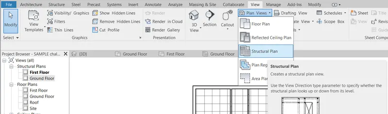
Select the VIEW TAB
Go to Create panel and select Plan views tool
Choose Structural plan from the dropdown list
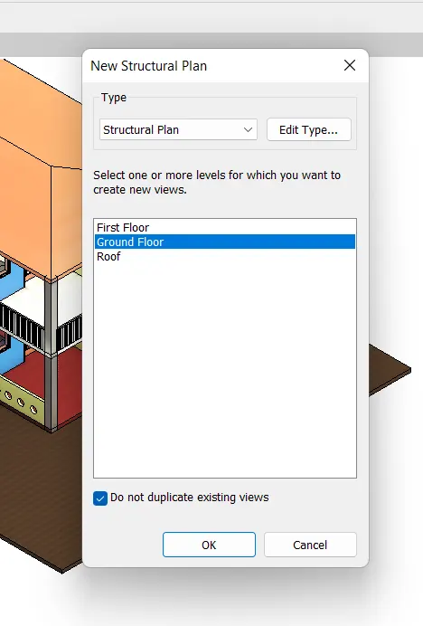
New Structural Plan Dialogue box opens
Select the Ground Floor from the available list.
Click OK
Type VG
Untick all the components created except walls, Floors, columns and staircase
Click Apply and then OK
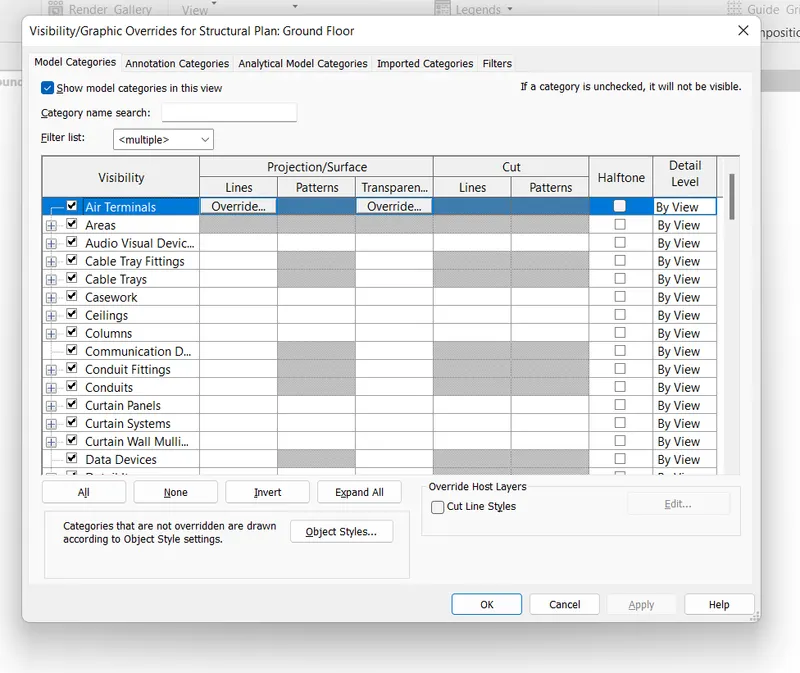
Structural Plan view for the Ground Floor is created.
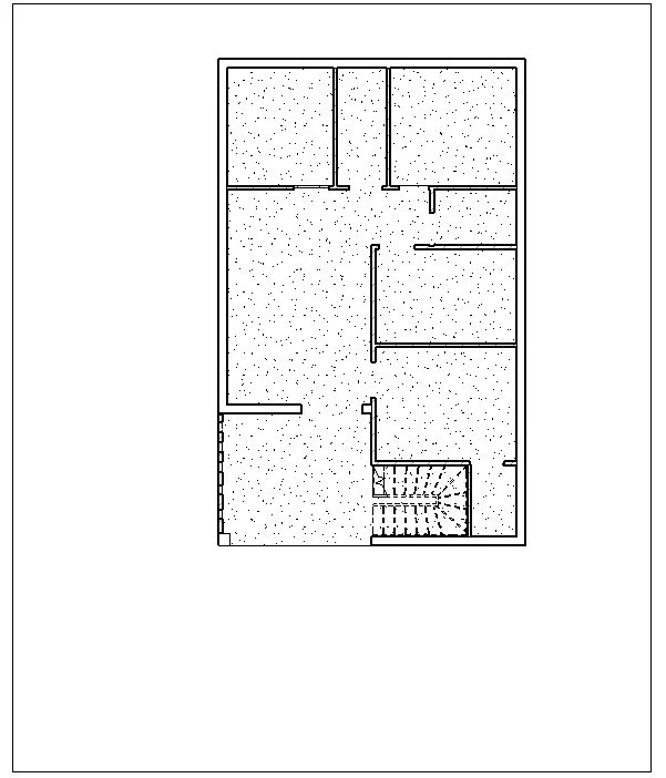
Select the VIEW TAB
Go to Create panel and select Plan views tool
Choose Structural plan from the dropdown list
New Structural Plan Dialogue box opens
Select the First Floor from the available list.
Click OK
Type VG
Untick all the components created except walls, Floors, columns and staircase
Click Apply and then OK
Structural Plan view for the First Floor is created.
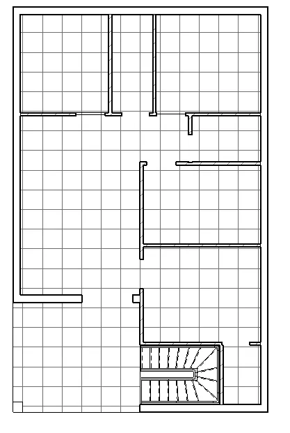
RESULT: -
We created Structural plan view for Ground Floor and Firs Floor
Walls, Floors, Columns and Staircase details are available in structural plan view
We created Architectural plan view for Ground floor and First Floor.
4Q]
AIM: -
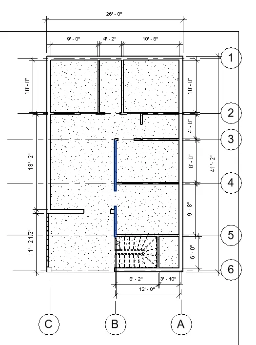
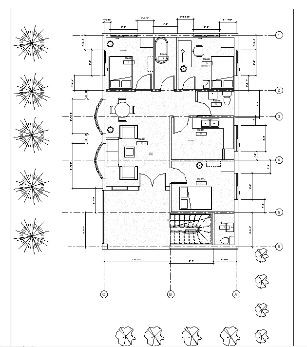
Create the Grids and mark the dimensions with reference to the Grids..
Include details on where the components are placed within the buildings with relation to grids in the Architectural plan
Include details on the position of all the walls and interior walls with reference to grids in the Structural plan.
PROCEDURE: -
In Architecture Tab
Go to DATUM panel and select GRIDS tool

Select Lines from Draw panel
Draw a Longitudinal line of certain distance
Move the cursor to the Text
Click on the Text and change the value to A
Grid line A is created
Draw the Transverse Gridlines from Top to Bottom.
Go to DATUM panel and select GRIDS tool
Select Pick Lines from Draw panel
Select centreline of the wall
Grid line B is created
Go to DATUM panel and select GRIDS tool
Select Pick Lines from Draw panel
Select centreline of the wall
Grid line C is created
Draw the Transverse Grid Lines
Go to DATUM panel and select GRIDS tool
Select Pick Lines from Draw panel
Select centreline of the wall
Grid line 1 is created
Select centreline of the wall
Grid line 2 is created
Select centreline of the wall
Grid line 3 is created
Select centreline of the wall
Grid line 4 is created
Select centreline of the wall
Grid line 5 is created
Select centreline of the wall
Grid line 6 is created
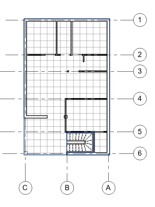
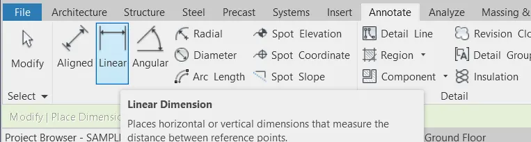
Select ANNOTATE Tab
Go to DIMENSION panel and choose LINEAR tool.
Choose carefully the Blue dot on either side of the wall and mark the dimensions of all the walls of each Room.
RESULT; -
We marked all the dimensions of the rooms.
The architecture plan dimensions included details of the components placed within the buildings with relation to grids.
The Structure plan dimensions include details on the position of all the walls and interior walls with reference to grids.
5Q]
AIM: -
Create a sheet template from the view tab
Adjust the parameters on the sheet to add appropriate views
PROCEDURE: -
Select VIEW TAB
Go to Sheet Composition Panel and click on Sheet tool

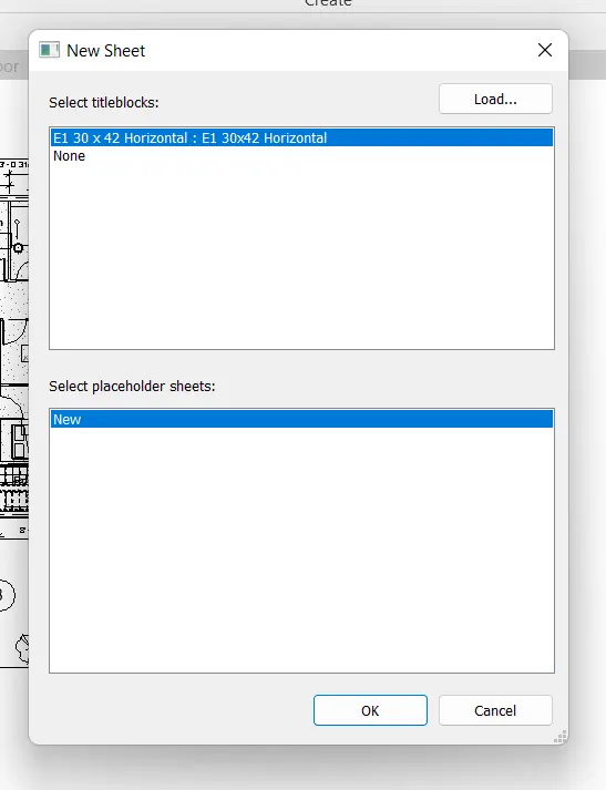
New Sheet dialogue box opens
Select one Titleblock
press OK
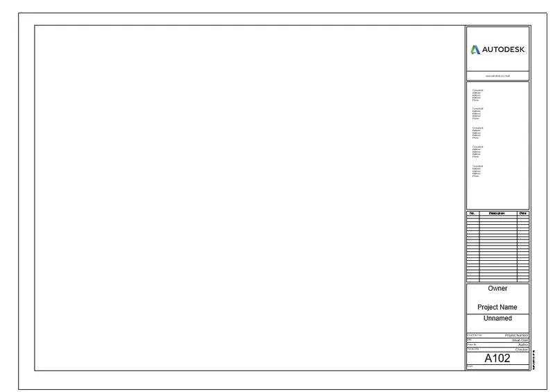
Sheet appears in the model space.
Select MANAGE TAB
Go to SETTINGS Panel and click on Project Information

Project Information dialogue box opens
Edit the data and press OK
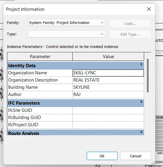
Data changes in the sheet.
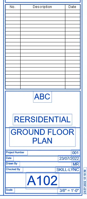
From the Project Browser, Go to Floor Plan column
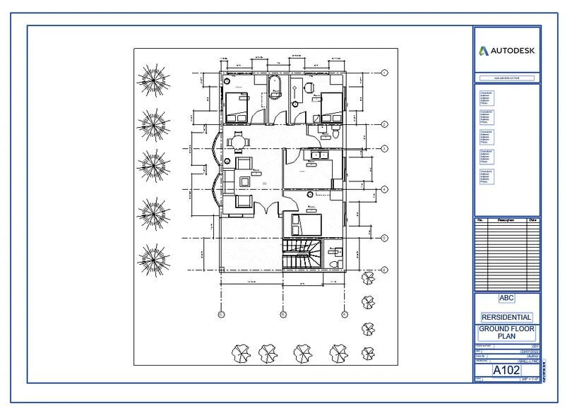
Select Ground Floor plan and drag it to the sheet.
Adjust the plan in the sheet.
RESULT: -
We created Sheet Template using View Tab
Edited the parameters using Project Information
Added plan to the sheet.
6Q]
AIM: -
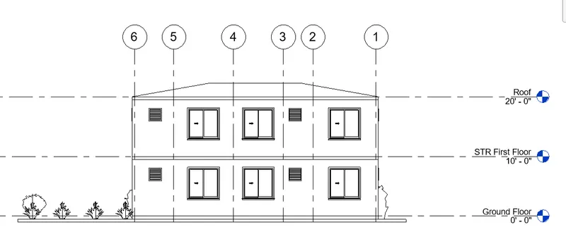
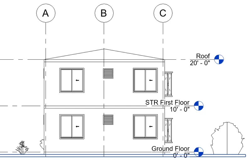
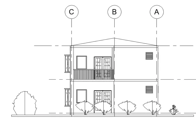
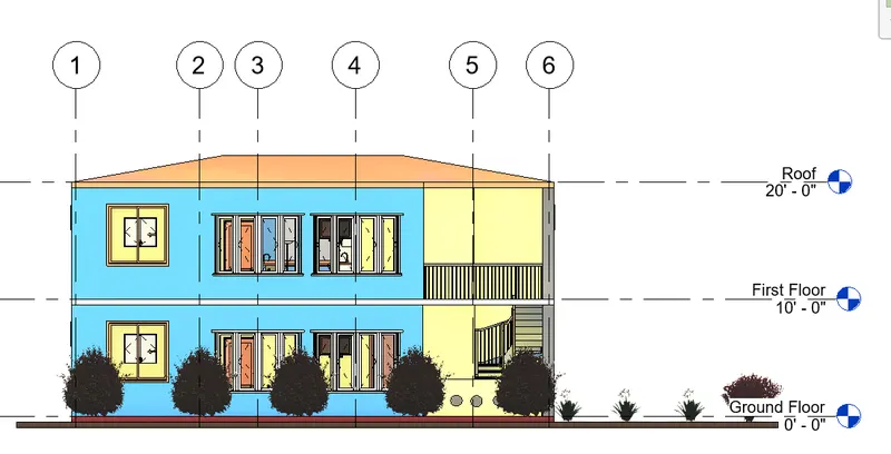
Create the Elevation View of the building from East, West, North and South
PROCEDURE: -
Select VIEW TAB
Go to CREATE panel and Select Elevation Tool
Choose Elevation option from the dropdown list

Bullet icon appears in the model space
Place these bullets in all the 4 sides: East, North, west and south
Go to Project Browser
Select Elevation column
Elevations views are created
Edit the name and change to East, North, south, West
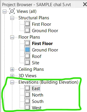
Click on the Elevation plan and open the model.
RESULT: -
We created the Elevation view of the building using View tab
We created 4 Elevation view of the building: East, North, south, West
7Q]
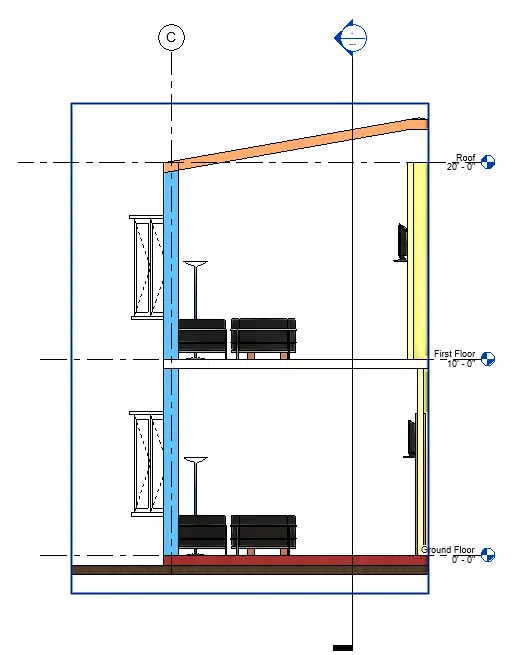
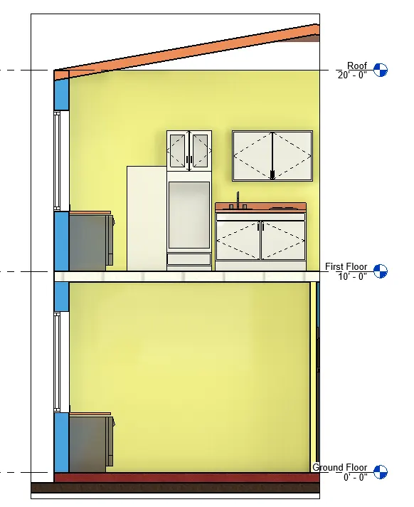
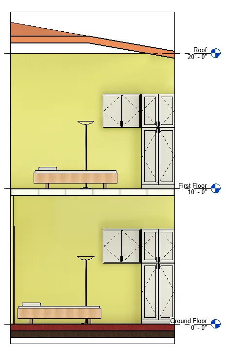
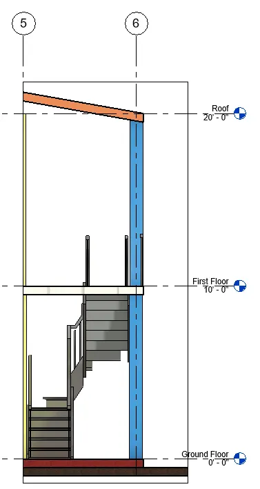
AIM: -
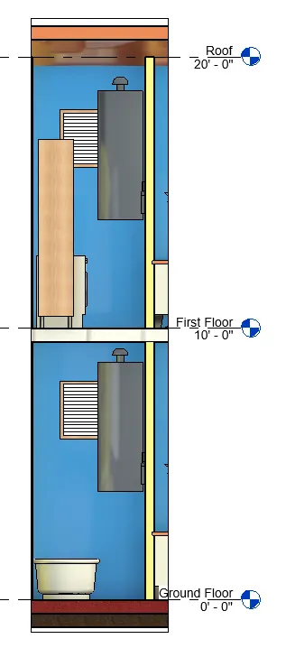
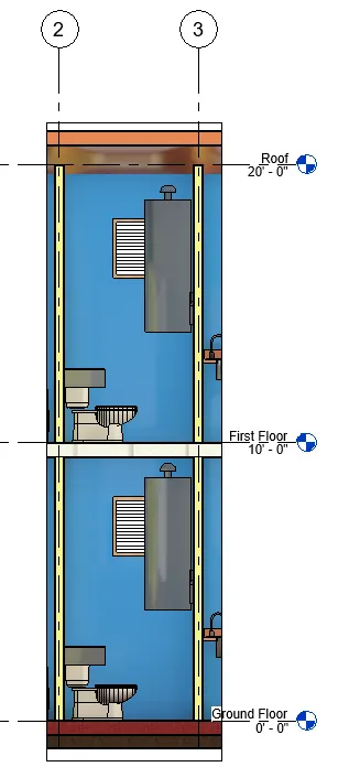
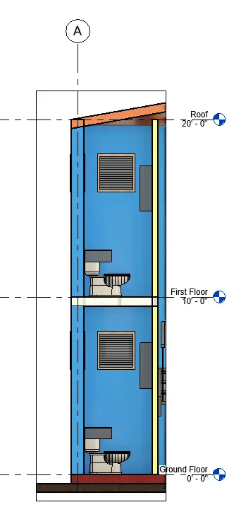
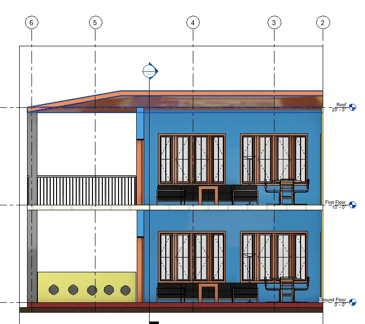
Create Section view of each room
PROCEDURE: -
Select VIEW TAB
Go to Create panel and choose Section tool

Mark the Section cut in each room either longitudinally or transversely on Ground Floor plan
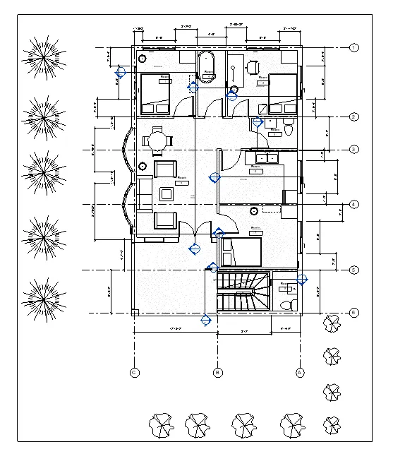
After placing the Section cut
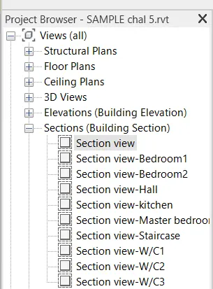
In Project Browser all the sections are placed under sections (building section)
RESULT: -
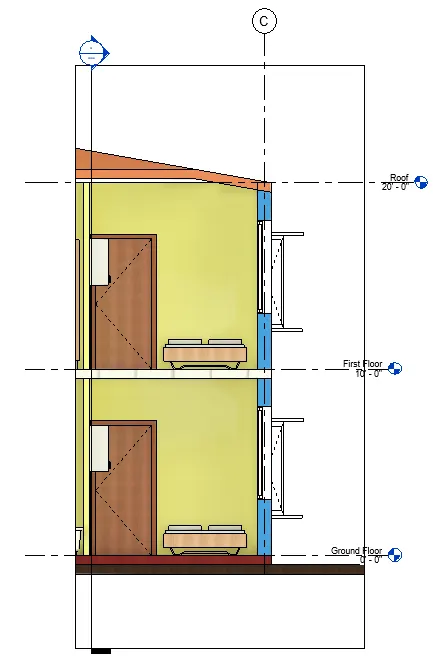
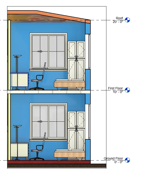
We created section view of each room.
8Q]
AIM: -
By using Properties Browser Classify the views, Plan views, Section views and Elevation views
PROCEDURE: -
Right click on the model space
Select the Browsers option from the dropdown list
Choose Project Browser from the list
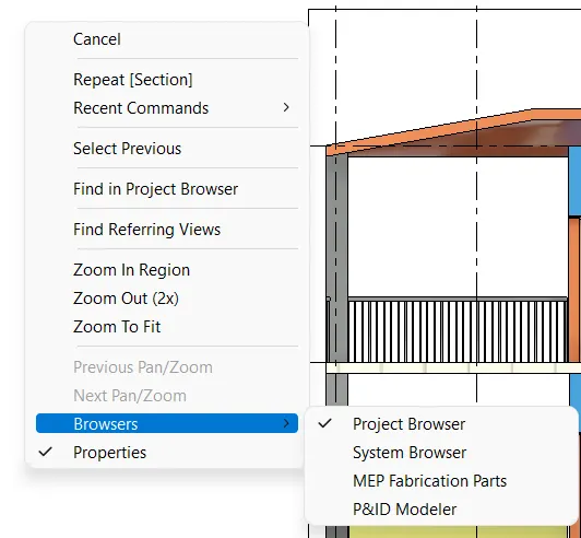
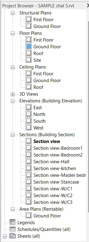
Under Project Browser, all the views are classified accordingly
RESULT: -
Using Properties browser, we classified the views, Plan Views, Section Views, and Elevation views to either Design or Documentation category
9Q]
AIM: -
By using the Sheet template create multiple sheets as follows:
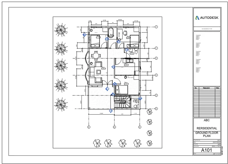
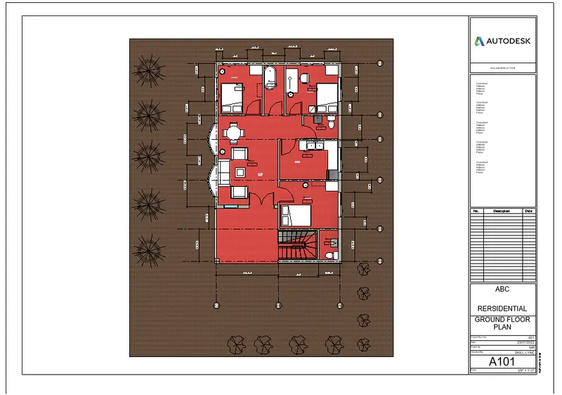
a.) A 101- Ground Floor Architecture Plan
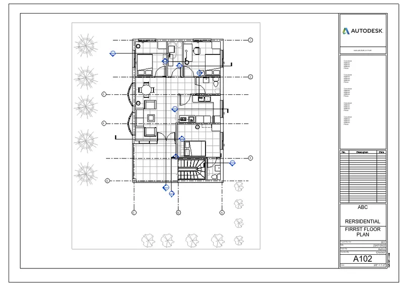
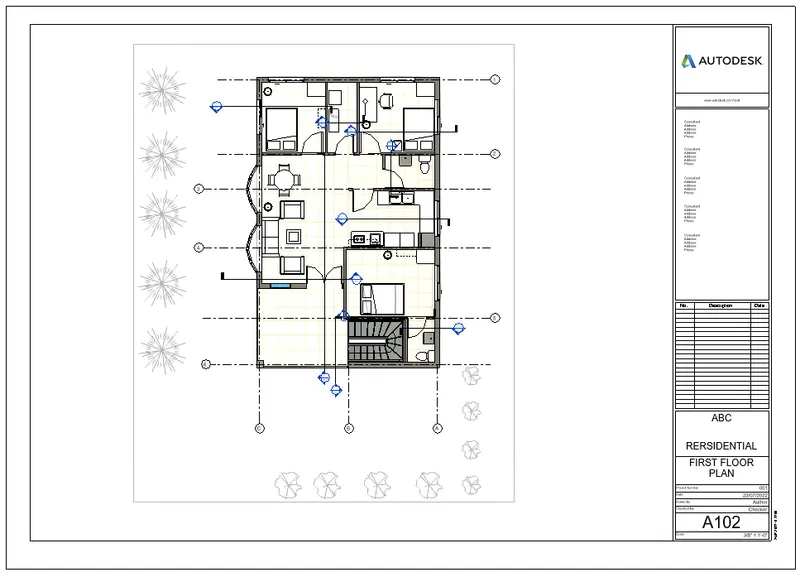
b.) A 102- First Floor Architecture Plan
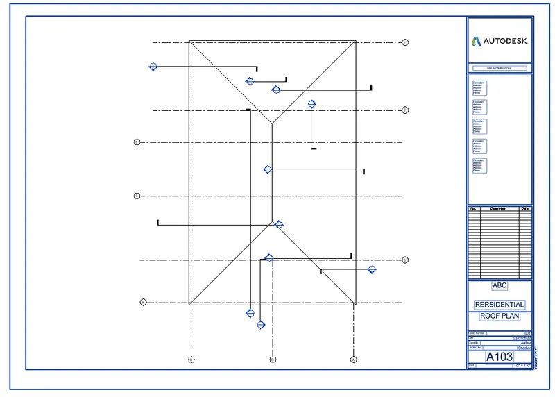
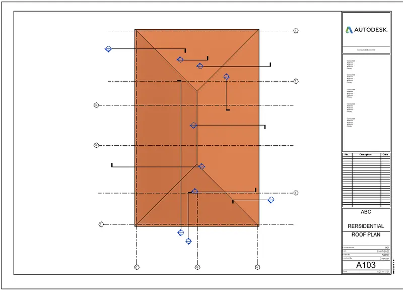
c.) A 103- Roof Plan
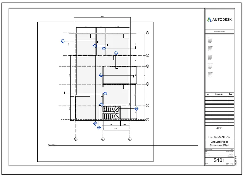
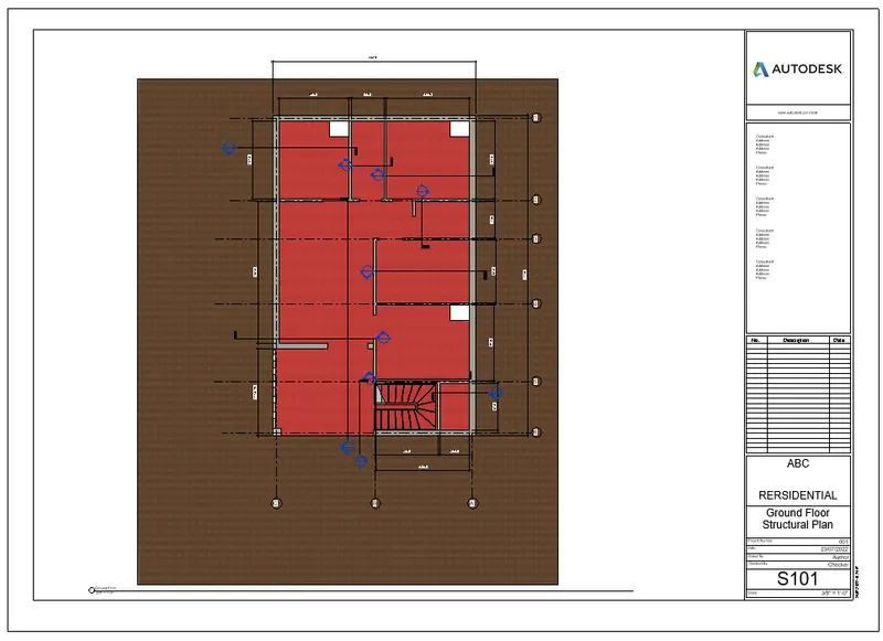
d.) S 101- Ground Floor Structural Plan
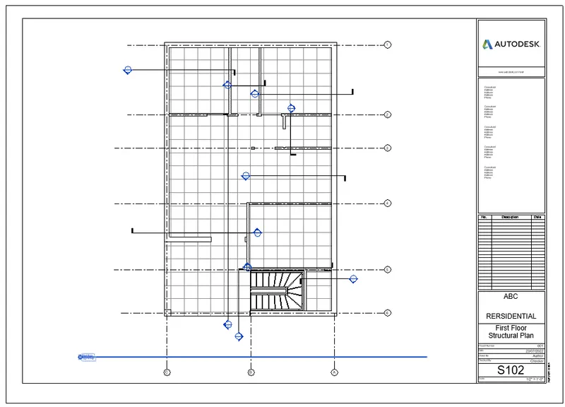
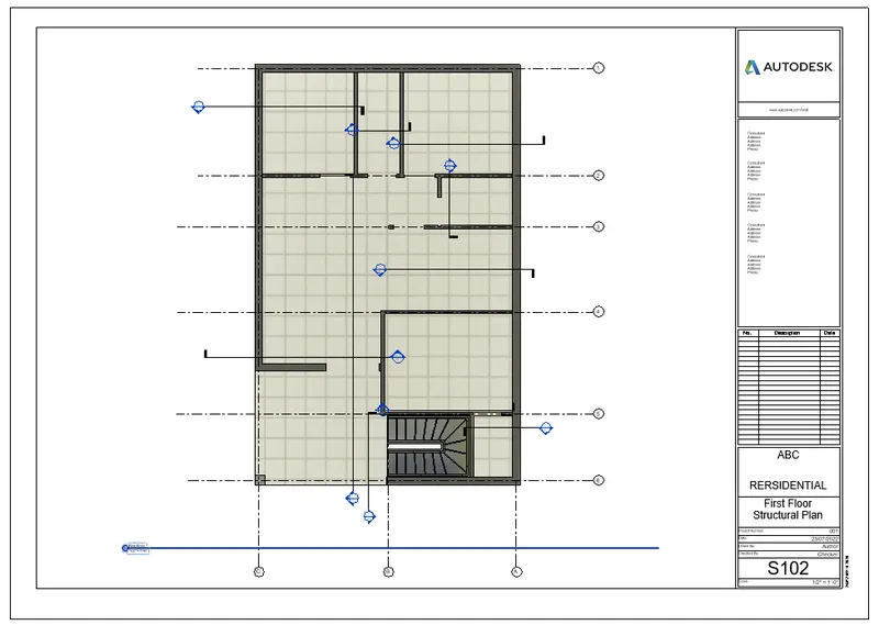
e.) S 102- First Floor Structural Plan
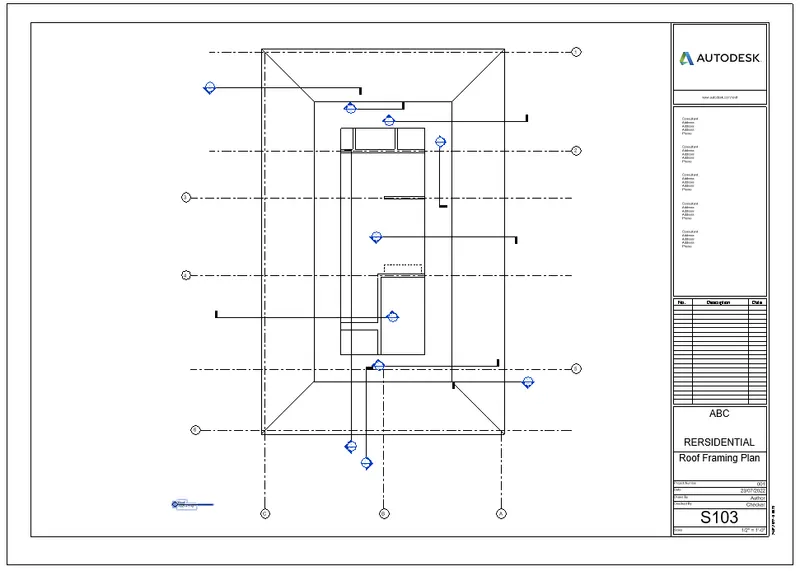
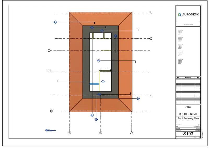
f.) S 103- Roof Framing Plan
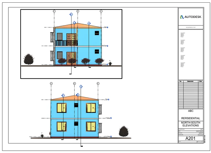
g.) A-201- North-South Elevations
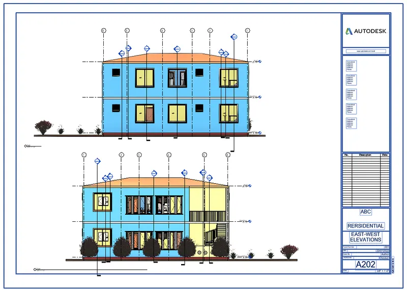
h.) A-202- East-West Elevations
PROCEDURE: -
Select VIEW TAB
Go to Sheet Composition Panel and click on Sheet tool
New Sheet dialogue box opens
Select one Titleblock
press OK
Sheet appears in the model space.
Select MANAGE TAB
Go to SETTINGS Panel and click on Project Information
Project Information dialogue box opens
Edit the data and press OK
Data changes in the sheet.
From the Project Browser, Go to Floor Plan column
Select Ground Floor plan and drag it to the sheet.
Adjust the plan in the sheet.
Set the scale: 3/8” = 1’-0”
Rename the sheet name: A 101- Ground Floor Architecture Plan
Select VIEW TAB
Go to Sheet Composition Panel and click on Sheet tool
New Sheet dialogue box opens
Select one Titleblock and press OK
Sheet appears in the model space.
From the Project Browser, Go to Floor Plan column
Select First Floor plan and drag it to the sheet.
Adjust the plan in the sheet.
Set the scale: 3/8” = 1’-0”
Rename the sheet name: A 102- FIRST Floor Architecture Plan
Select VIEW TAB
Go to Sheet Composition Panel and click on Sheet tool
New Sheet dialogue box opens
Select one Titleblock and press OK
Sheet appears in the model space.
From the Project Browser, Go to Floor Plan column
Select ROOF plan and drag it to the sheet.
Adjust the plan in the sheet.
Set the scale: 3/8” = 1’-0”
Rename the sheet name: A 103- ROOF PLAN
Select VIEW TAB
Go to Sheet Composition Panel and click on Sheet tool
New Sheet dialogue box opens
Select one Titleblock and press OK
Sheet appears in the model space.
From the Project Browser, Go to Structural Plan column
Select Ground Floor plan and drag it to the sheet.
Adjust the plan in the sheet.
Set the scale: 3/8” = 1’-0”
Rename the sheet name: S101- GROUND FLOOR STRUCTURAL PLAN
Select VIEW TAB
Go to Sheet Composition Panel and click on Sheet tool
New Sheet dialogue box opens
Select one Titleblock and press OK
Sheet appears in the model space.
From the Project Browser, Go to Structural Plan column
Select Ground Floor plan and drag it to the sheet.
Adjust the plan in the sheet.
Set the scale: 3/8” = 1’-0”
Rename the sheet name: S102- FIRST FLOOR STRUCTURAL PLAN
Select VIEW TAB
Go to Sheet Composition Panel and click on Sheet tool
New Sheet dialogue box opens
Select one Titleblock and press OK
Sheet appears in the model space.
From the Project Browser, Go to Structural Plan column
Select Ground Floor plan and drag it to the sheet.
Adjust the plan in the sheet.
Set the scale: 3/8” = 1’-0”
Rename the sheet name: S103- ROOF FRAMING PLAN
Select VIEW TAB
Go to Sheet Composition Panel and click on Sheet tool
New Sheet dialogue box opens
Select one Titleblock and press OK
Sheet appears in the model space.
From the Project Browser, Go to ELEVATIONS column
Select Ground Floor plan and drag it to the sheet.
Adjust the plan in the sheet.
Set the scale: 3/8” = 1’-0”
Rename the sheet name: A201-NORTH SOUTH ELEVATIONS
Select VIEW TAB
Go to Sheet Composition Panel and click on Sheet tool
New Sheet dialogue box opens
Select one Titleblock and press OK
Sheet appears in the model space.
From the Project Browser, Go to ELEVATIONS column
Select Ground Floor plan and drag it to the sheet.
Adjust the plan in the sheet.
Set the scale: 3/8” = 1’-0”
Rename the sheet name: A202- EAST WEST ELEVATIONS
RESULT: -
We created Sheet Template using View Tab
Edited the parameters using Project Information
Added plans to the sheets.
Renamed the sheets and set the scale.
10Q]
AIM: -
Create 3D view in each room
Create new set of sheets to place the 3d view images.
Name the sheets starting with number A501 and so on
PROCEDURE: -
Select Ground Floor Plan in the Project browser
Select VIEW TAB
Go to CREATE panel and click on 3D view
Choose camera from the dropdown list

Place the camera in Bedroom-1
3D view of the room is stored under 3D views column in Project Browser
Double click on the view and rename it
Open the 3D view of Bedroom-1 and set the visual style to realistic
Choose camera from the dropdown list
Place the camera in Bedroom-2
3D view of the room is stored under 3D views column in Project Browser
Double click on the view and rename it
Open the 3D view of Bedroom-2 and set the visual style to realistic
Choose camera from the dropdown list
Place the camera in KITCHEN
3D view of the room is stored under 3D views column in Project Browser
Double click on the view and rename it
Open the 3D view of KITCHEN and set the visual style to realistic
Choose camera from the dropdown list
Place the camera in MASTER BEDROOM
3D view of the room is stored under 3D views column in Project Browser
Double click on the view and rename it
Open the 3D view of MASTER BEDROOM and set the visual style to realistic
Choose camera from the dropdown list
Place the camera in HALL
3D view of the room is stored under 3D views column in Project Browser
Double click on the view and rename it
Open the 3D view of HALL and set the visual style to realistic
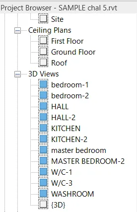
All the images are stored in 3D views column in Project Browser
Select VIEW TAB
Go to Sheet Composition Panel and click on Sheet tool
New Sheet dialogue box opens
Select one Titleblock and press OK
Sheet appears in the model space.
From the Project Browser, Go to 3D VIEWS column
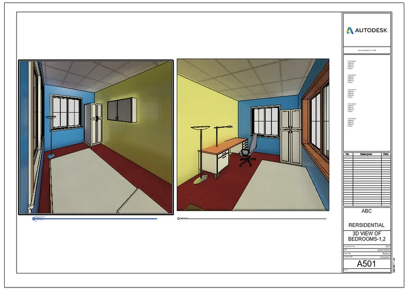
Select BEDROOM-1 view and drag it to the sheet.
Select BEDROOM-2 view and drag it to the sheet.
Adjust the plan in the sheet.
Click on the 3d view
In Modify Viewports, choose SIZE CROP

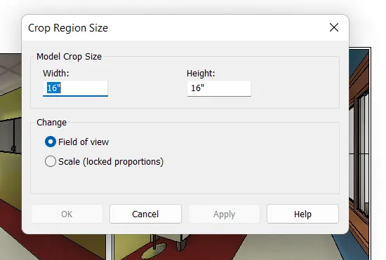
CROP REGION SIZE dialogue box appears on the screen
Set the width and Height
Press OK
Rename the sheet name: A501- 3D VIEW OF BEDROOMS-1,2
Select VIEW TAB
Go to Sheet Composition Panel and click on Sheet tool
New Sheet dialogue box opens
Select one Titleblock and press OK
Sheet appears in the model space.
From the Project Browser, Go to 3D VIEWS column
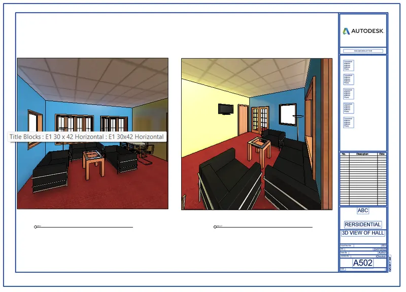
Select HALL-1 view and drag it to the sheet.
Select HALL-2 view and drag it to the sheet.
Adjust the plan in the sheet.
Click on the 3d view
In Modify Viewports, choose SIZE CROP
CROP REGION SIZE dialogue box appears on the screen
Set the width and Height
Press OK
Rename the sheet name: A502- 3D VIEW OF HALL
Select VIEW TAB
Go to Sheet Composition Panel and click on Sheet tool
New Sheet dialogue box opens
Select one Titleblock and press OK
Sheet appears in the model space.
From the Project Browser, Go to 3D VIEWS column
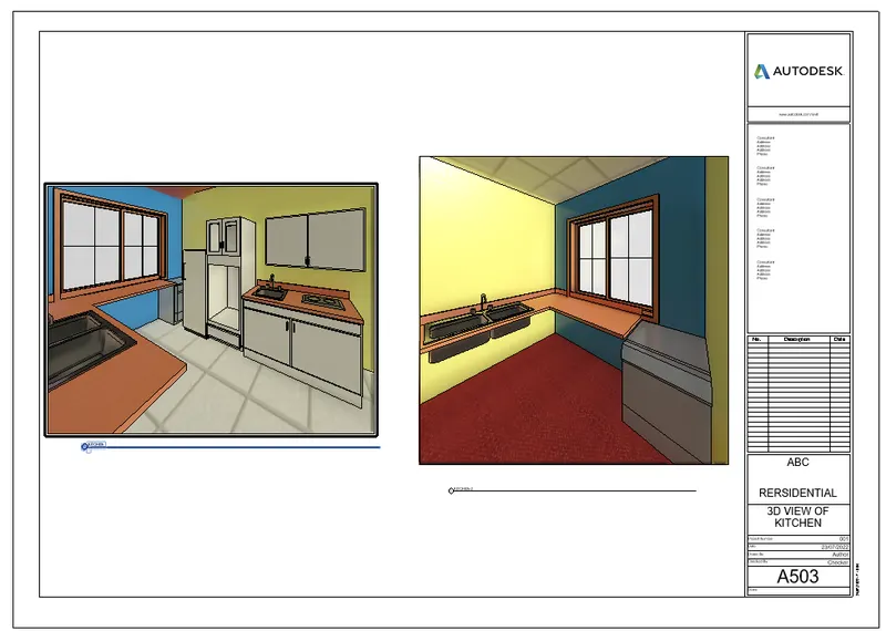
Select KITCHEN-1 view and drag it to the sheet.
Select KITCHEN-2 view and drag it to the sheet.
Adjust the plan in the sheet.
Click on the 3d view
In Modify Viewports, choose SIZE CROP
CROP REGION SIZE dialogue box appears on the screen
Set the width and Height
Press OK
Rename the sheet name: A503- 3D VIEW OF KITCHEN
Select VIEW TAB
Go to Sheet Composition Panel and click on Sheet tool
New Sheet dialogue box opens
Select one Titleblock and press OK
Sheet appears in the model space.
From the Project Browser, Go to 3D VIEWS column
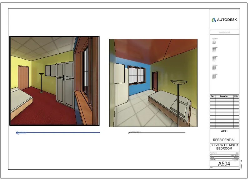
Select MASTER BEDROOM-1view and drag it to the sheet.
Select MASTER BEDROOM-2 view and drag it to the sheet.
Adjust the plan in the sheet.
Click on the 3d view
In Modify Viewports, choose SIZE CROP
CROP REGION SIZE dialogue box appears on the screen
Set the width and Height
Press OK
Rename the sheet name: A504- 3D VIEW OF MASTER BEDROOM
Select VIEW TAB
Go to Sheet Composition Panel and click on Sheet tool
New Sheet dialogue box opens
Select one Titleblock and press OK
Sheet appears in the model space.
From the Project Browser, Go to 3D VIEWS column
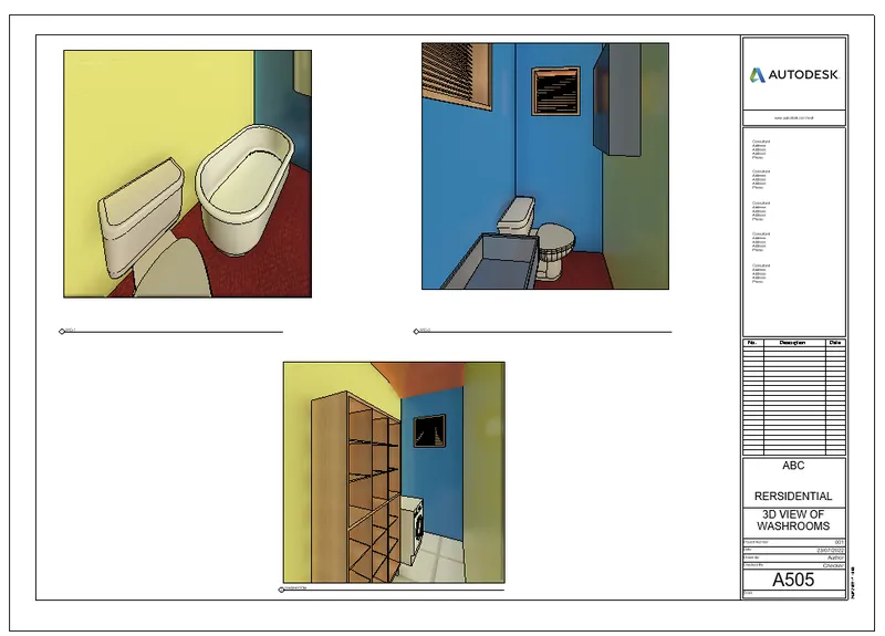
Select W/C-1 view and drag it to the sheet.
Select W/C-2 view and drag it to the sheet.
Select WASHROOM view and drag it to the sheet.
Adjust the plan in the sheet.
Click on the 3d view
In Modify Viewports, choose SIZE CROP
CROP REGION SIZE dialogue box appears on the screen
Set the width and Height
Press OK
Rename the sheet name: A505- 3D VIEW OF WASHROOMS
RESULT: -
We created 3D view of each room
Created new set of sheets to place the 3d view images.
Named the sheets as per given numbers.