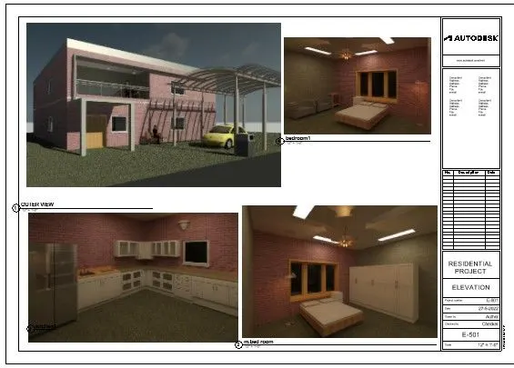
3D Creation of Celing, Roof, Architectural plan, Structural plan, Sectional view, Elevation view and Camera specific view for a house plan using REVIT
AIM-1: Based on the project saved from Week 3, proceed from the First Floor Level. Model a Ceiling from the architecture tab above the walls at the first-floor level
PROCEDURE:
- Now open previous drawing using open icon fron file tab in left of working scren
- select ceiling icon in architecture tab we get display editing tools in ribion with 2 option related draw ceiling or automatic ceiling.
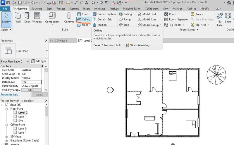

- if we select automatic ceiling designing designing of rooms
- if we select the sketch the ceiling we another editing options

- in that select a pic-line option select the walls outer edge selecting draw ceiling
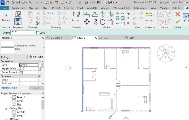
- click right mark after completed lineing of ceiling.
RESULTS:
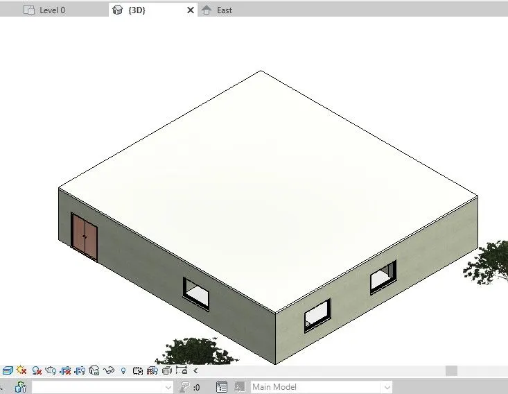
AIM-2: Model a roof above the ceiling by selecting the footprints of the ceiling. Using the adjustment toolbars appearing on-screen adjust the roof slope to 10 degrees
PROCEDURE:
- open the previous drawing
- click on the roof buttion then we get multple roling options contain
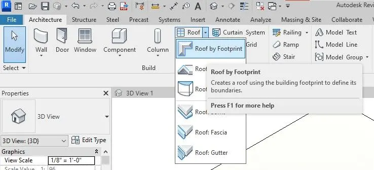
- select roof by footprint we get another ribion tool tan appear with editing options

- select pic-line option and select outer edges of walls floor created
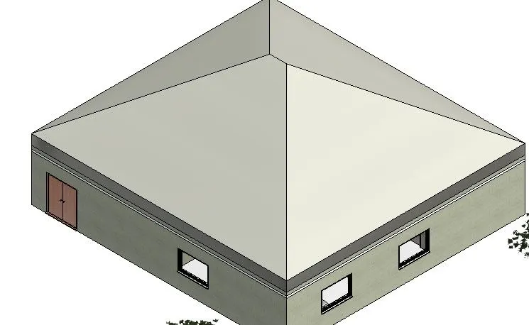
- as per given question we roof ramp degrees in 10 degrees so edit the roof by select the roof
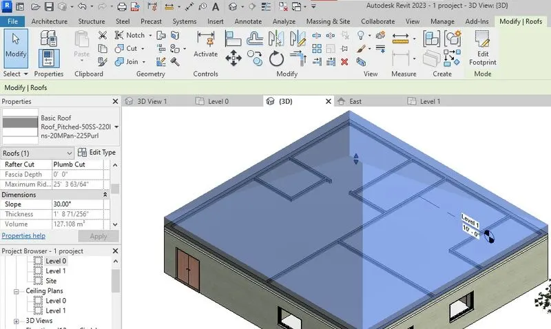
- that roof details are reflected in the properties browcer in that details in dimentions we get slop then edit that slop in 10 degrees
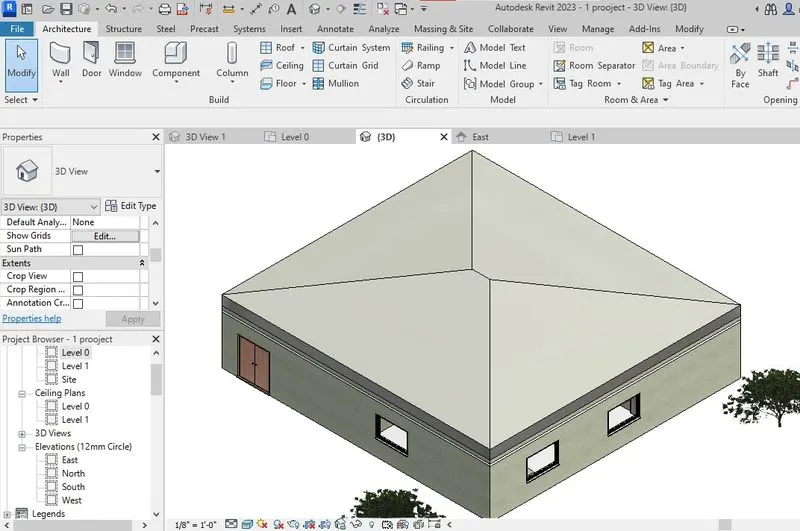
RESULTS:
AIM-3:
Using the file saved from weeks 2 to 4, create plan views for ground floor level and first-floor level including all the walls, floors, and components. Separate them to
architecture and structural plans
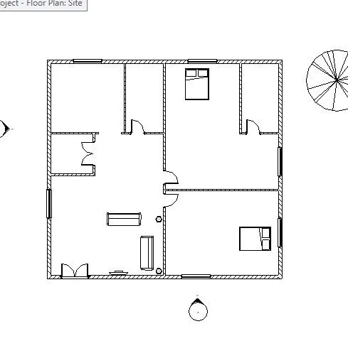
a. Architecture plan must have walls, floors, and all the components placed within the building
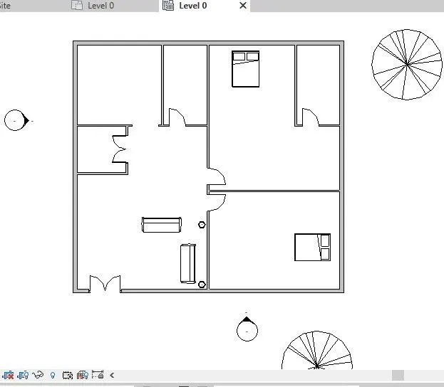
b. Structure plan must have details of only walls, floors, and columns
PROCEDURE:
- open the previous plan in challenge we created
- select the view tab on architeture tab select plan views

- we rolling titles from plan view
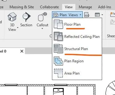
- we can appear what selected in that rolling titles
- if we select the floor plan we plan views pop-up window releated to the select level of floor plan and click ok.
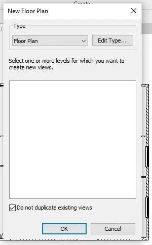
- if we select the starctural plan similerly we get the pop-up window
- to select the level the which stratural plan we want.
RESULTS:
STARCTURAL PLAN
ARCHITECTURAL PLAN:
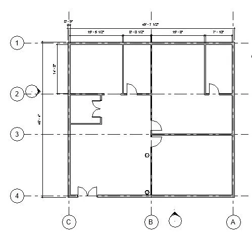
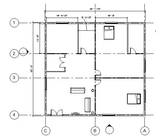
AIM-4:Using annotate toolbar add dimensions to all the walls and floors with reference to the longitudinal and transverse grids created in the project file
a. The architecture plan dimensions include details on where the components are placed within the buildings with relation to grids. Overall dimensions are sufficient for architecture plans
b. The Structure plan dimensions must include details on the position of all the walls and interior walls with reference to grids. Locate all the framing components of the building with reference to a fixed point using Structural plans
PROCEDURE:
- open the previous plan and select the stractural plan drawing add grids to that with respectively walls

- place the grid lines in wall center to be placed
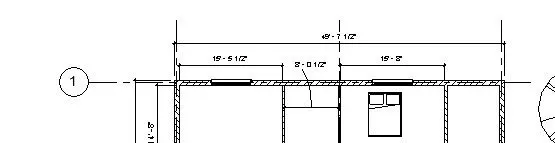
- add dimentions from annotation tab
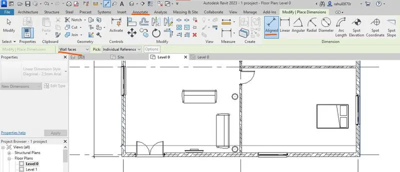
- select linear dimentions to dimention the walls
- slect annotation < alingned < selct wall faces < select outer edge< click dimention places
RESULTS:
STRACTURAL
ARCHITECTURAL
AIM-5:Create a sheet template from the view tab and adjust the parameters on the sheet to add appropriate views
PROCEDURE:
- open previous dawing
- select view tab and select sheet icon in ribbion

- we got a pop-up window to select template
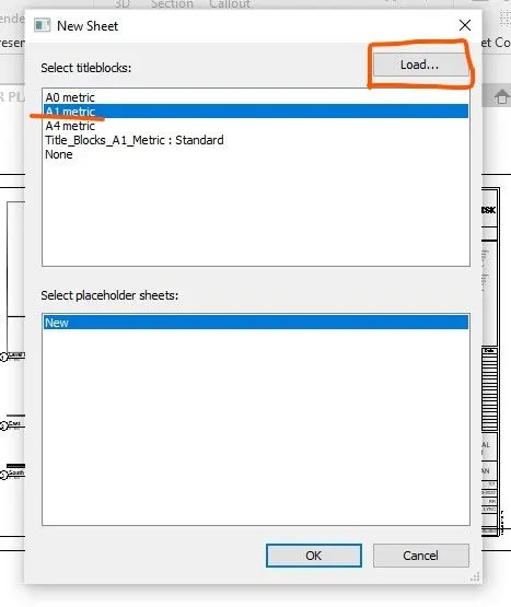
- if we select the load icon get another window we get from load family templates window
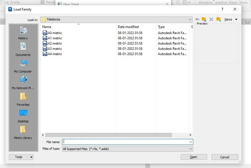
- select require tamplate open another tab in revit working screen window
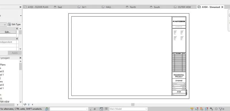
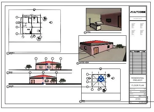
- after that drag the view from project browcer plac ein to the template if w cando any scale adjustment project browcer window
RESULTS:
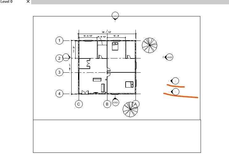
AIM-6:sing the elevation tab create the elevation views, looking at your building from East, North, South, and West
PROCEDURE:
- open the drawing defultly we get the elevation icons project browcer
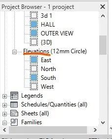
- if didnt get that in project browcer go to view tab in ribbion < slection elevation< selct the position or direction of view < click ok it's created

- if we creted newly then we get pateculer icon created in project browcer in elevation family
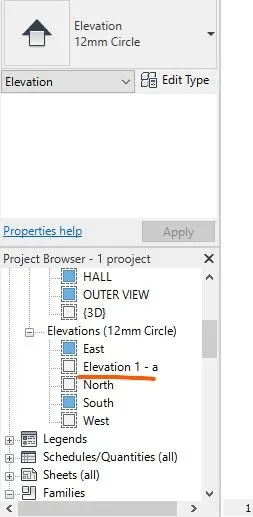
- If we right click we get option releated rename,delete and duplicate view.
- we click on the elevation instances in project browcer we get a view on that direction of project.
RESULTS:
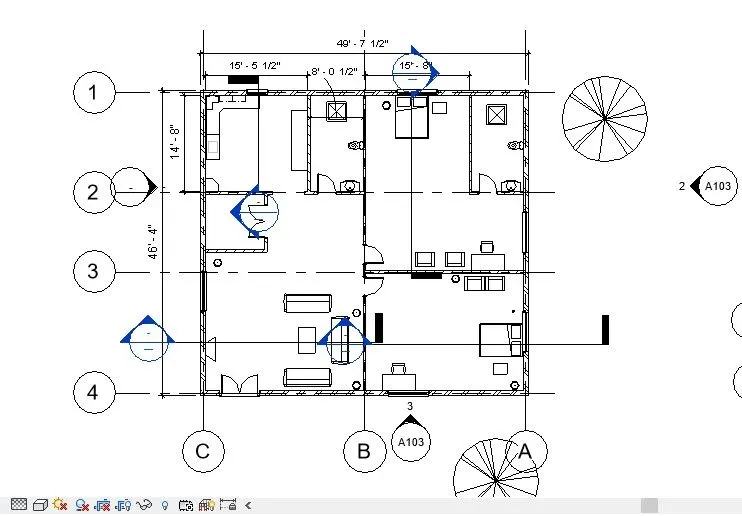
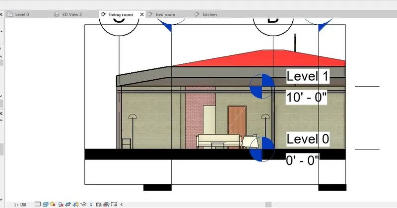
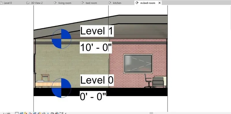
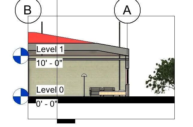
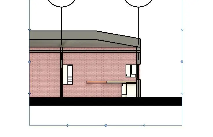
AIM-7: Produce section cut through each room either cutting across longitudinally or in a transverse direction
PROCEDURE:
- open the previous file in the revit
- now selec the view ta in riddion select section icon in the tools
- now place adjust the range of section object
-

RESULTS:
LIVING ROOM
M.BEDROOM
BED ROOM
KITCHEN
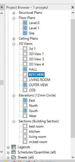
8: Classify the views, Plan Views, Section Views, and Elevation views to either Design or Documentation category using Properties browser
ANS: THESE ALL THE VIEW ARE shown in the project browcer
AIM-9:Using the sheet template produced create multiple sheets as follows
a. A 101- Ground Floor Architecture Plan
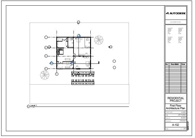
b. A 102- First Floor Architecture Plan
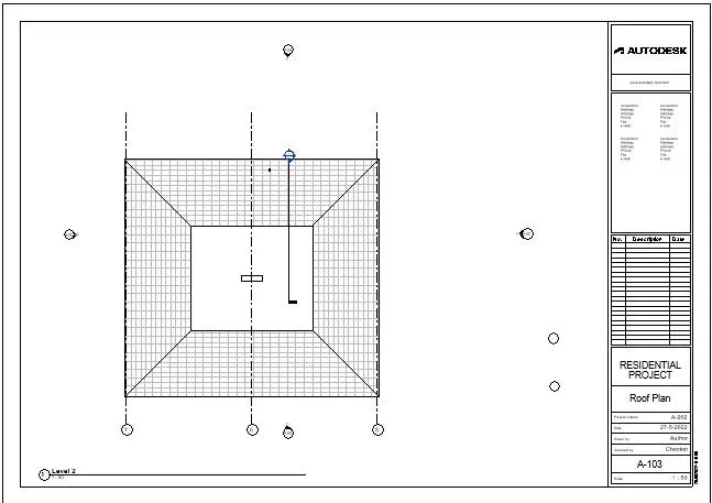
c. A 103- Roof Plan
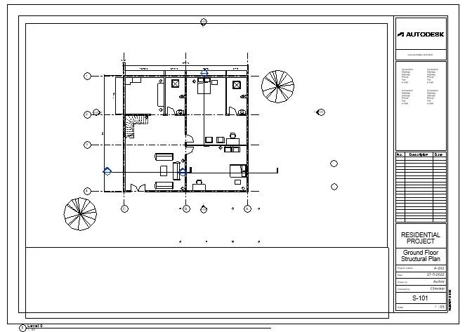
d. S 101- Ground Floor Structural Plan
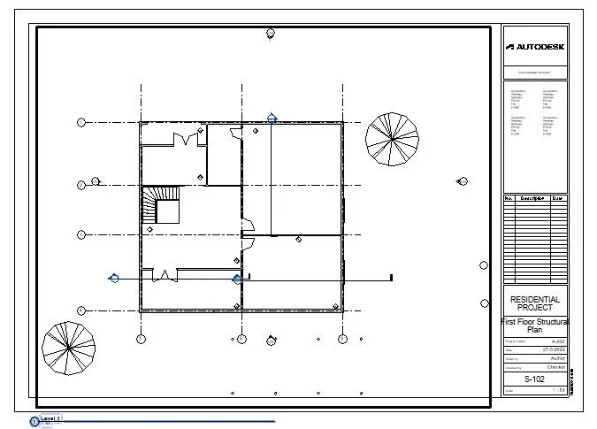
e. S 102- First Floor Structural Plan
f. S 103- Roof Framing Plan
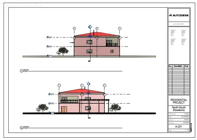
g. A-201- North-South Elevations
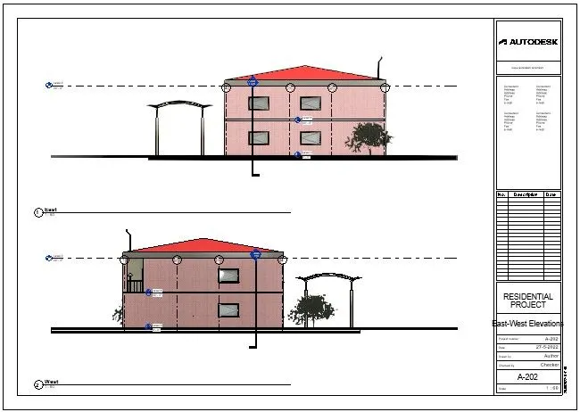
h. A-202- East-West Elevations
PROCEDURE:
- Open the previous drawing by the shortcut key in upper left corner or from file tab
- go to view tab in the ribbion select the sheets icon
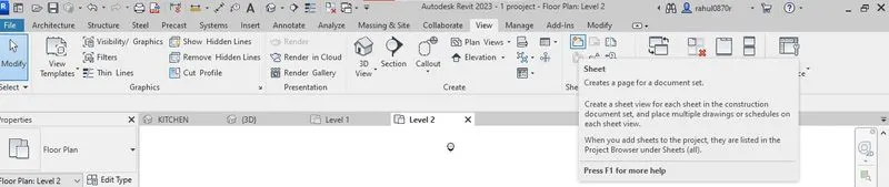
- now we get the pop-up window related sheet
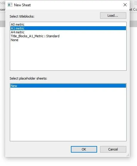
- select the A1 matric then it is notavailable then click on the load icon and attach the file of template
- after the click ok open the template file then drag the views into the template
- if it is larger than a size of template adjust the scale from property browcers
RESULTS:
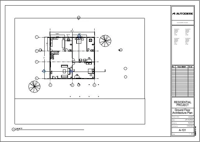
A 101- Ground Floor Architecture Plan
A 102- First Floor Architecture Plan
A 103- Roof Plan
S 101- Ground Floor Structural Plan
S 102- First Floor Structural Plan
A-201- North-South Elevations
A-202- East-West Elevations
AIM-10:
Create a camera-specific view or a 3D view in each room ( living, dining, bedroom). Based on the views create a new set of sheets starting A-501 (you can add as many sheets after, 502, 503.. n)to place the 3D view images. Produce the sheets as a part of project drafting.
PROCEDURE:
- Open the previous drawing by the shortcut key in upper left corner or from file tab
- go to view tab in the ribbion select the sheets icon
- now we get the pop-up window related sheet
- select the A1 matric then it is notavailable then click on the load icon and attach the file of template
- after the click ok open the template file then drag the views into the template
- if it is larger than a size of template adjust the scale from property browcers
- Now place a cemera from view tab< cemara < place cemera in hall in require place where we want
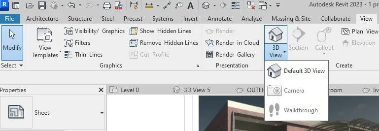
- now go again into view ta select render icon we get another window regarding rendering settings
- click render to rendering happen
RESULTS: