3D Creation of Celing, Roof, Architectural plan, Structural plan, Sectional view, Elevation view and Camera specific view for a house plan using REVIT
ANS.1.
AIM:-
To create the ceiling from architectural tab using revit software.
INTRODUCTION :-
Revit is a commercial building information modeling (BIM) software by the company Autodesk.It’s generally used by architects, structural engineers, mechanical, electrical, and plumbing (MEP) engineers, designers, and contractors. Autodesk Revit allows users to create, edit, and review 3D models in exceptional detail.
PROCEDURE :-
Open the Revit software , and open the file that you have created.
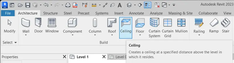
After opening the file go to the architecture tab and then click on the ceiling option.
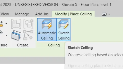
Then the Ribbon tab changes and hence click on the sketch ceiling option.
After that select the type from which you want to draw the ceiling on the walls.
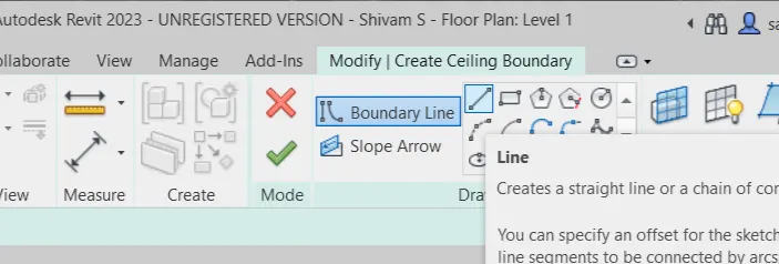
After that select the outer area of the walls by clicking on the pick line option and click on the tick mark to proceed.
After that the ceilings has been drawn and to cross check it go to the 3D view to view the ceiling.
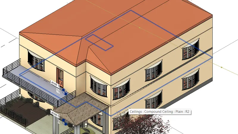
RESULT :-
Hence ceiling has been drawn above the walls at the firsy floor level using revit software.
ANS.2.
AIM :-
To create the roof of the building and then edit the roof slope as 10 degree using revit software.
INTRODUCTION :-
Revit is a commercial building information modeling (BIM) software by the company Autodesk.It’s generally used by architects, structural engineers, mechanical, electrical, and plumbing (MEP) engineers, designers, and contractors. Autodesk Revit allows users to create, edit, and review 3D models in exceptional detail.
PROCEDURE :-
Open the file and then go to the architecture tab where you will find the roof option click on the roof option and then click on the roof by footprint option to draw the roof.
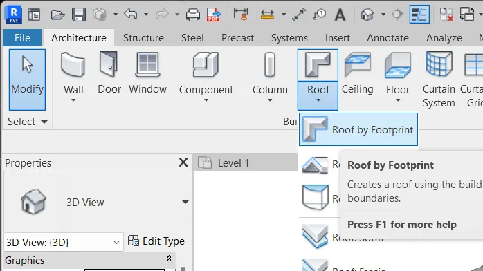
After that select the walls as same as ceiling selection procedure and then click ok to proceed.
As you can see the roof has been drawn of the building as per the desired level
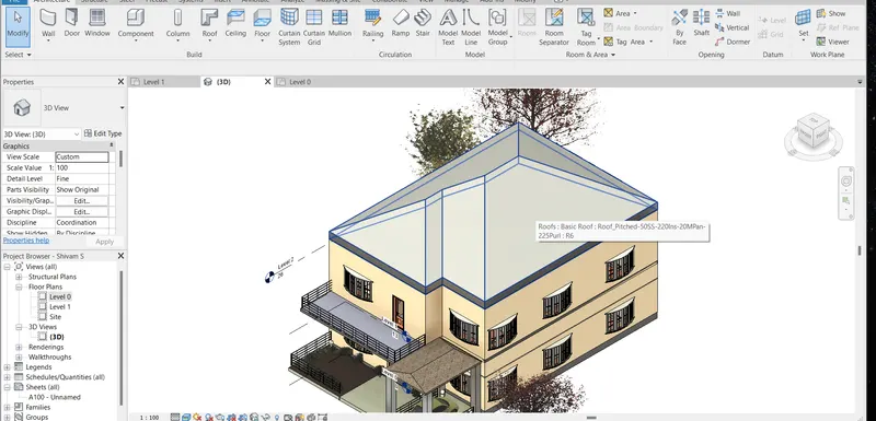
Then to edit the slope of the roof
Select the roof and then go to the project Browser where you will find the option of slope in dimension
Provide the slope as 10° and click apply.
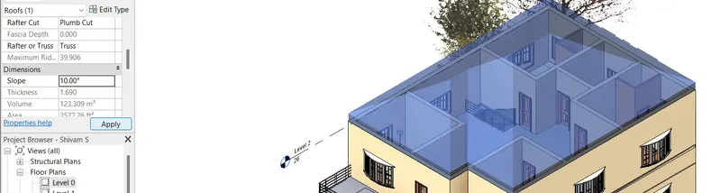
Now the desired slope of the building roof has been created.
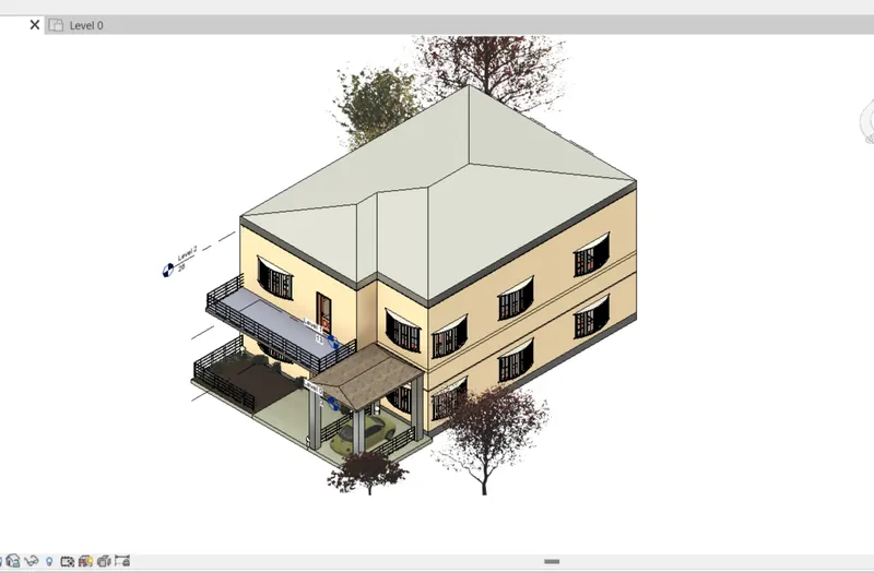
RESULT :-
Hence ,the roof has been created using architecture tab in the drawn building and also the slope has been modified to 10°
ANS.3.
AIM:-
To create plan views for ground floor level and first floor level including all the components of the building and also to separate them to architectural structural plans.
INTRODUCTION :-
Revit is a commercial building information modeling (BIM) software by the company Autodesk.It’s generally used by architects, structural engineers, mechanical, electrical, and plumbing (MEP) engineers, designers, and contractors. Autodesk Revit allows users to create, edit, and review 3D models in exceptional detail.
PROCEDURE :-
Open the file which you have created.
Go to the view tab and then click on the plan views option

After clicking on that many options will appear .click on the floor plan option.
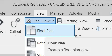
After clicking on the floor plan option A dialogue box will appear just click on ok and proceed.
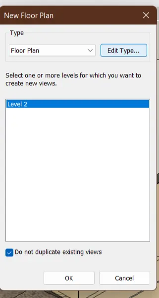
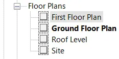
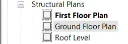
The different levels created using the floor plan option are shown below
You can also rename the plans by right clicking on them and then go to the rename option and then renamed them as per requirement.
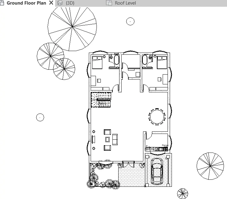
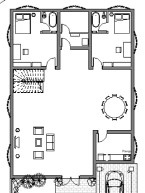
The ground floor plan is shown below
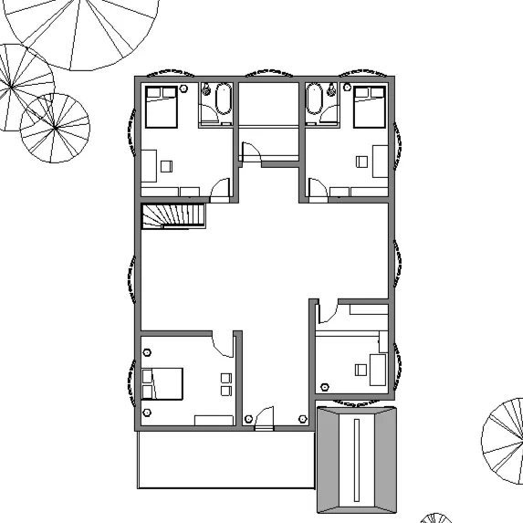
First floor plan is attached below which is created using the plan views option
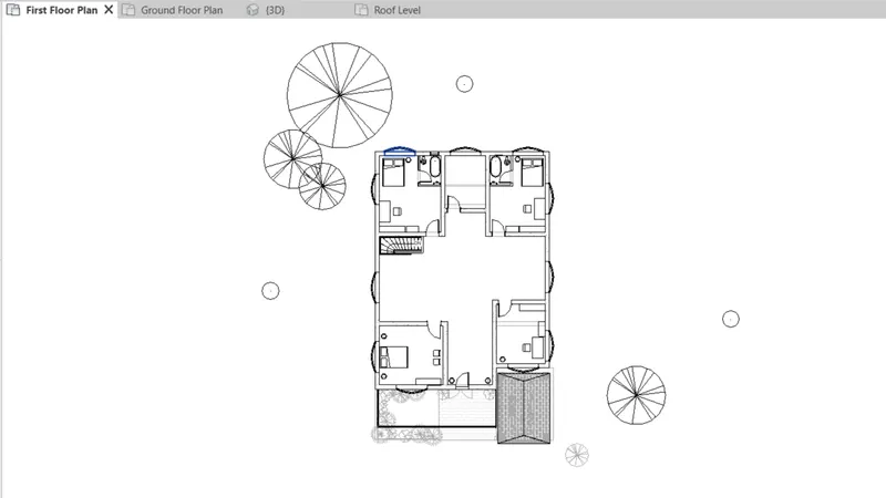
Roof level has also been attached below
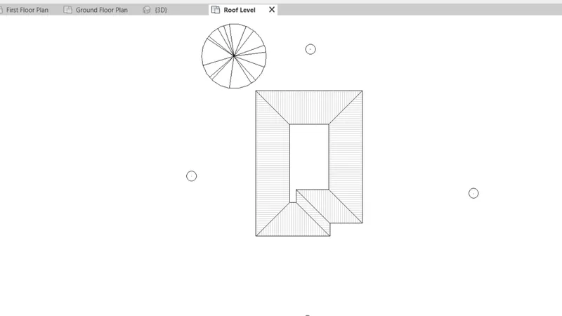
Now to create the structural plan
Again go to the view tab
Click on the plan views option and then select the structural plan option
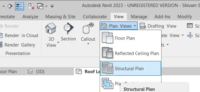
Again dialogue box will open
Select the first floor plan and then click on ok.
Follow the same procedure to draw the structural ground floor plan.
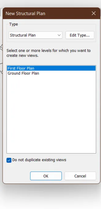
Hence the ground floor structural plan is created and attached
Similarly the first floor structural plan is also created in attached below.
This is the overall view from the project Browser of the structural plan
RESULT :-
Hence , floor plans and structural plan are being created using the plan views option
ANS.4
AIM :-
To add dimensions to the creator floor plan and structural plan using the annotate toolbar
INTRODUCTION :-
Revit is a commercial building information modeling (BIM) software by the company Autodesk.It’s generally used by architects, structural engineers, mechanical, electrical, and plumbing (MEP) engineers, designers, and contractors. Autodesk Revit allows users to create, edit, and review 3D models in exceptional detail.
PROCEDURE :-
Open the project file
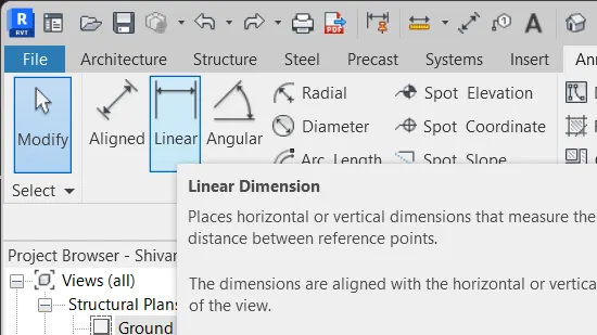
Go to the annotate toolbar
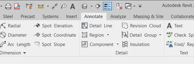
After clicking on the added toolbar the Ribbon tab changes and their occurs many different options of dimensioning.
Select any of the dimensioning object and then click ok.
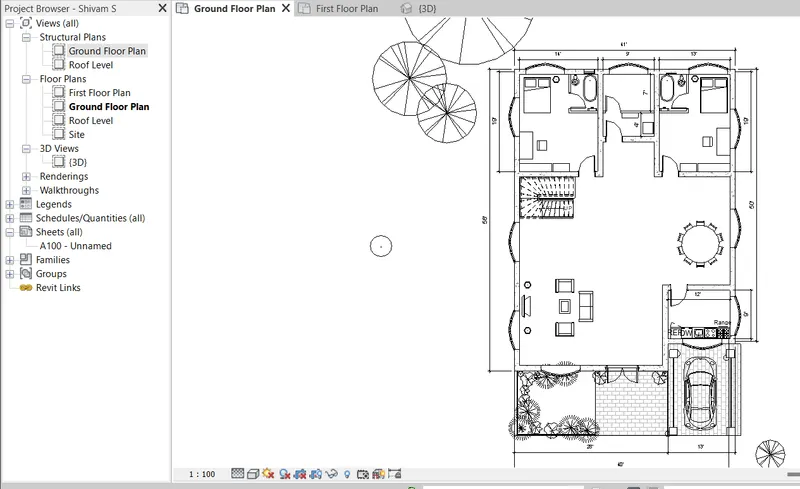
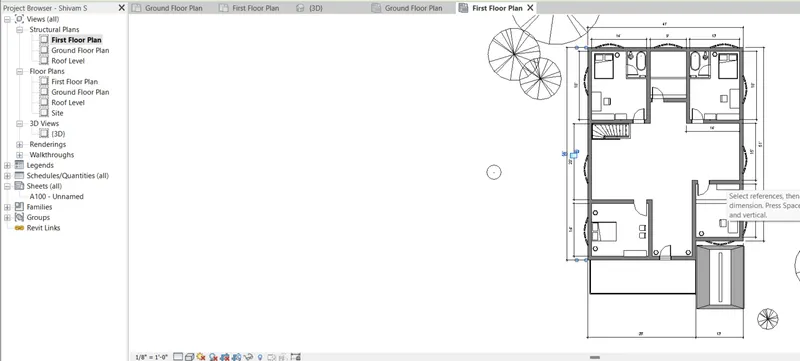
Then go to the plan and just dimension the figure as per the given conditions
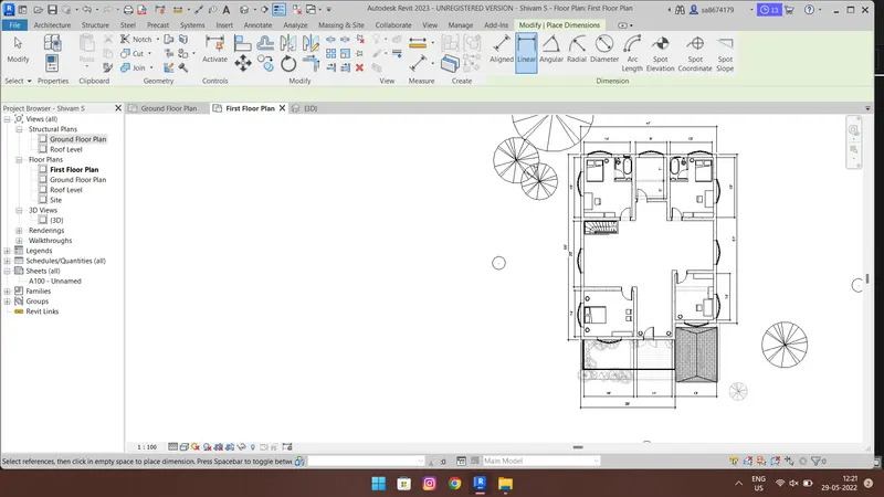
Similarly the first floor plan for floor plans is also dimension using the dimension tool from annoted toolbar
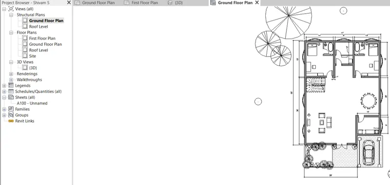
After the floor plans open the structural plan and do the dimensioning using the same procedure
RESULT :-
Hence the created plants such as architectural and structural are being dimension using annotated tool bar
ANS.5.
AIM :-
To create a seat template from the view tab and also adjust the parameters on the sheet to add appropriate views.
INTRODUCTION :-
Revit is a commercial building information modeling (BIM) software by the company Autodesk.It’s generally used by architects, structural engineers, mechanical, electrical, and plumbing (MEP) engineers, designers, and contractors. Autodesk Revit allows users to create, edit, and review 3D models in exceptional detail.
PROCEDURE :-
Open the file which you have created earlier.
Then go to the view tab and click on the sheet option available there.

After picking on the sheet option there opens a dialog box in which you can select the title block as per your requirement or load from the family option
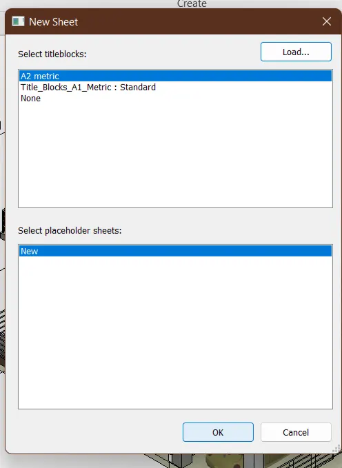
After selection the template , drag the view which you want to place in there.
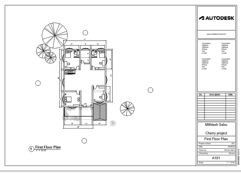
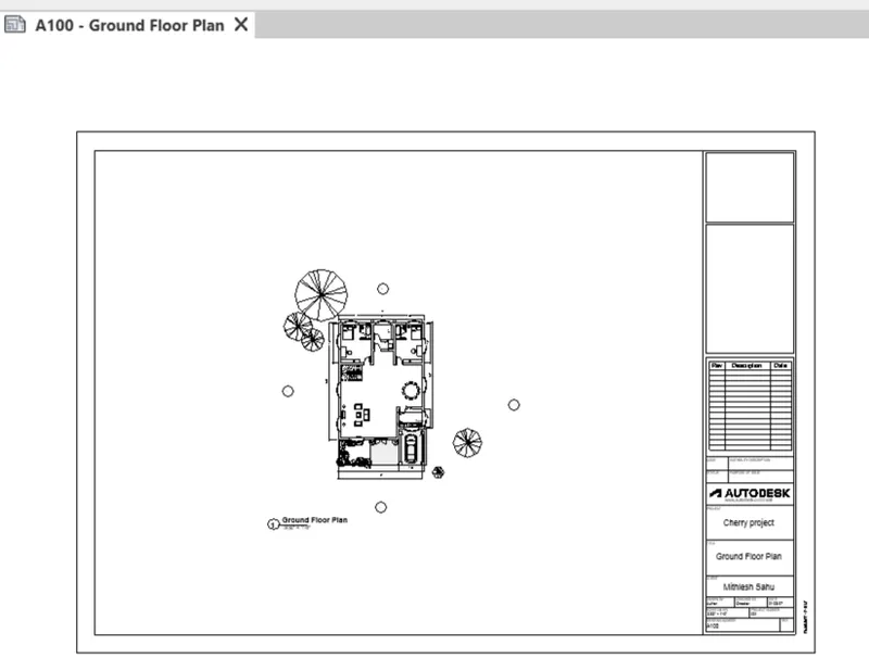
Here I have place the first floor and the ground floor plan in the sheets.
You can also adjust the scale of plans as per you ajustments.
First floor plan sheet view :-
Ground floor plan sheet view :-
RESULT :-
Hence , sheet templates have been created and different floor plans has also been added to them .
ANS.6.
AIM:-
To create the elevation views looking at the building from east north south and West
INTRODUCTION :-
Revit is a commercial building information modeling (BIM) software by the company Autodesk.It’s generally used by architects, structural engineers, mechanical, electrical, and plumbing (MEP) engineers, designers, and contractors. Autodesk Revit allows users to create, edit, and review 3D models in exceptional detail.
PROCEDURE :-
Open the created file
Go to the view tab and then click on the elevation view option.
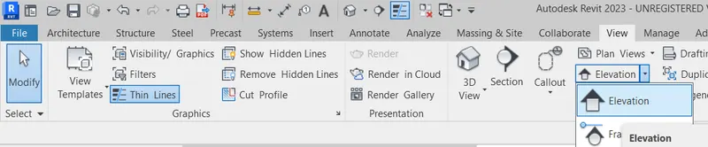
After that place the circles that are given by clicking on the elevation tab in the north direction , south direction , east direction and West direction
Then go to the property Browser where you will find the different views that you have created as an elevation.
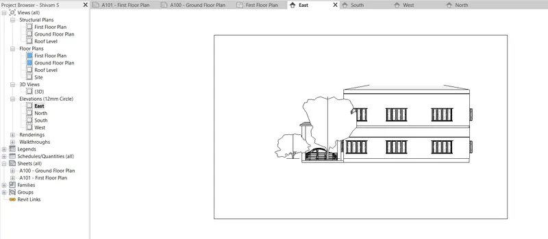
Created elevation view of East direction is attached below
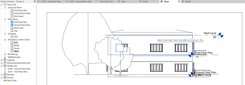
Created elevation view of best direction is attached below
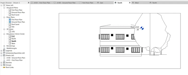
Created elevation view of south direction is attached below
Created elevation view of north direction is attached below
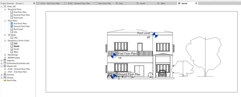
RESULT :-
Hence different views have been created and attached using the elevation view in the figure.
ANS.7.
AIM :-
To create the section cut in the figure using the section option in longitudinal or in transverse direction.
INTRODUCTION :-
Revit is a commercial building information modeling (BIM) software by the company Autodesk.It’s generally used by architects, structural engineers, mechanical, electrical, and plumbing (MEP) engineers, designers, and contractors. Autodesk Revit allows users to create, edit, and review 3D models in exceptional detail.
PROCEDURE :-
Open the file which you have drawn
Then go to the view tab and there you will find the section option
Click on the section option
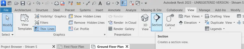
After clicking on the section option then we will have to select the area where we have to provide the section of the building
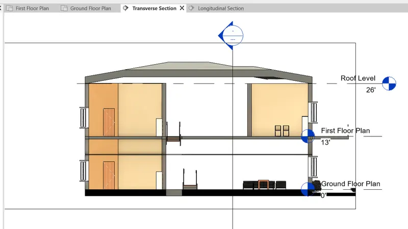
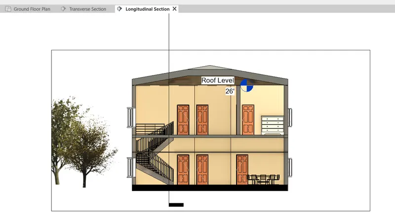
Here I have selected the transverse and longitudinal section direction and they are attached below
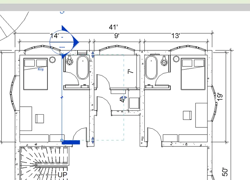
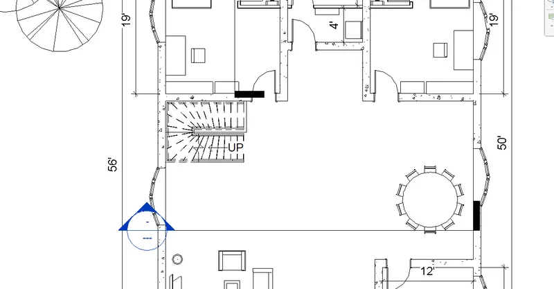
Therefore
Transverse section created in the figure is attached below
Longitudinal section created is attached below
RESULT :-
Given section has been created and also attached in the file.
ANS.8.
AIM:-
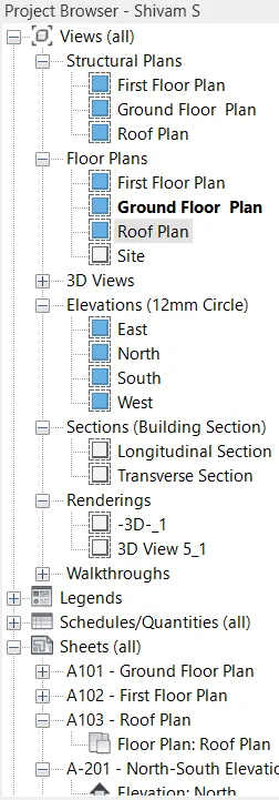
To classify the views, plan views, section views and elevation views to either design or documentation category using the properties Browser.
INTRODUCTION :-
Revit is a commercial building information modeling (BIM) software by the company Autodesk.It’s generally used by architects, structural engineers, mechanical, electrical, and plumbing (MEP) engineers, designers, and contractors. Autodesk Revit allows users to create, edit, and review 3D models in exceptional detail.
PROCEDURE :-
Open the file in which you have created the different views
Then go to the project Browser and they are you will find all the views that you have created as a document
RESULT :-
Hence the different views that are created are classified using the properties browser and attached in the file.
ANS.9.
AIM:-
Using the sheet template we have to create multiple sheets as mentioned in the question.
INTRODUCTION :-
Revit is a commercial building information modeling (BIM) software by the company Autodesk.It’s generally used by architects, structural engineers, mechanical, electrical, and plumbing (MEP) engineers, designers, and contractors. Autodesk Revit allows users to create, edit, and review 3D models in exceptional detail.
PROCEDURE :-
Open the file and then go to the view tab
After going to the view tab click on the sheet option that is available there
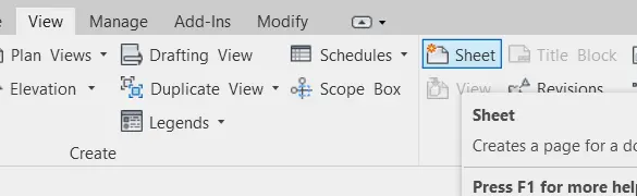
After clicking on the sheet option you will have a dialogue box opened
From there you have to select the title block as per the requirement and then drag the views that are required from the project Browser
Given views in the question are renamed and attached below :
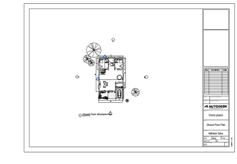
A101- ground floor architectural plan
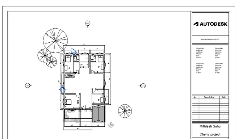
A102 first floor architectural plan
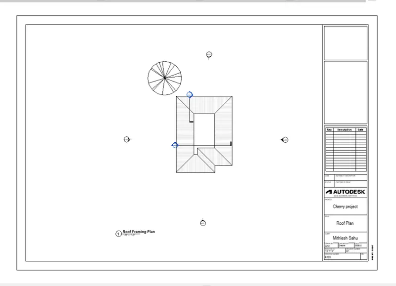
A103- ROOF PLAN
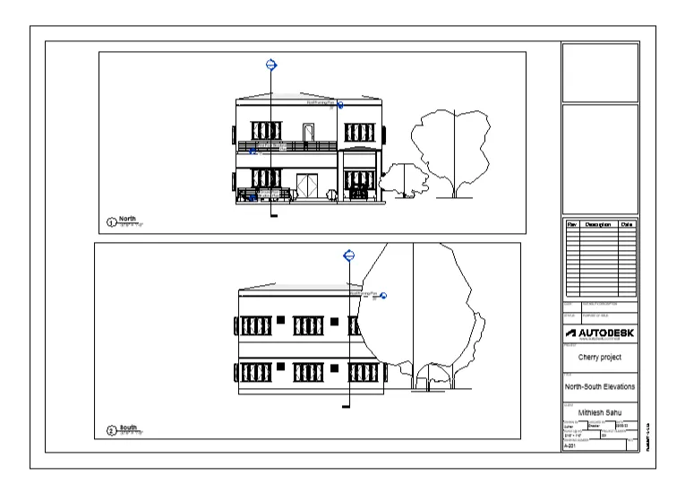
A201 - north south elevations
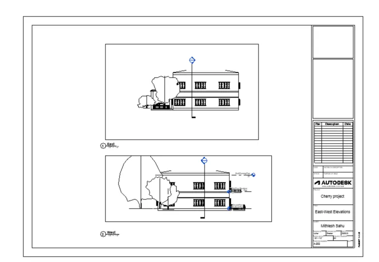
A202 - east west elevations
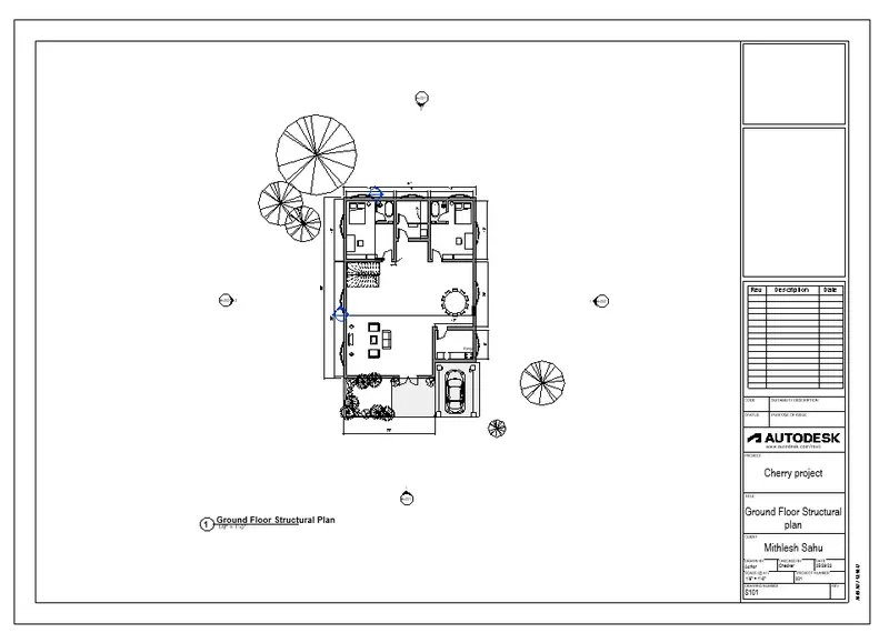
S101 - ground floor structural plan
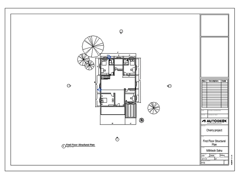
S102- first floor structural plan
RESULT :-
Hence multiple sheets have been created and also the different plans have been added to the sheets.
ANS.10.
AIM :-
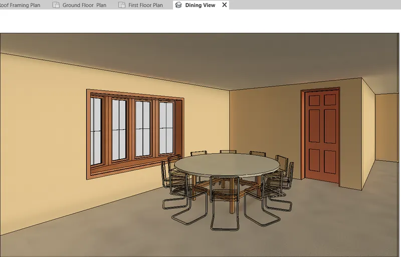
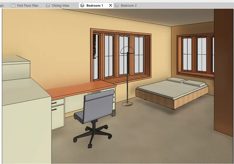
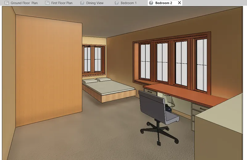
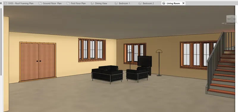
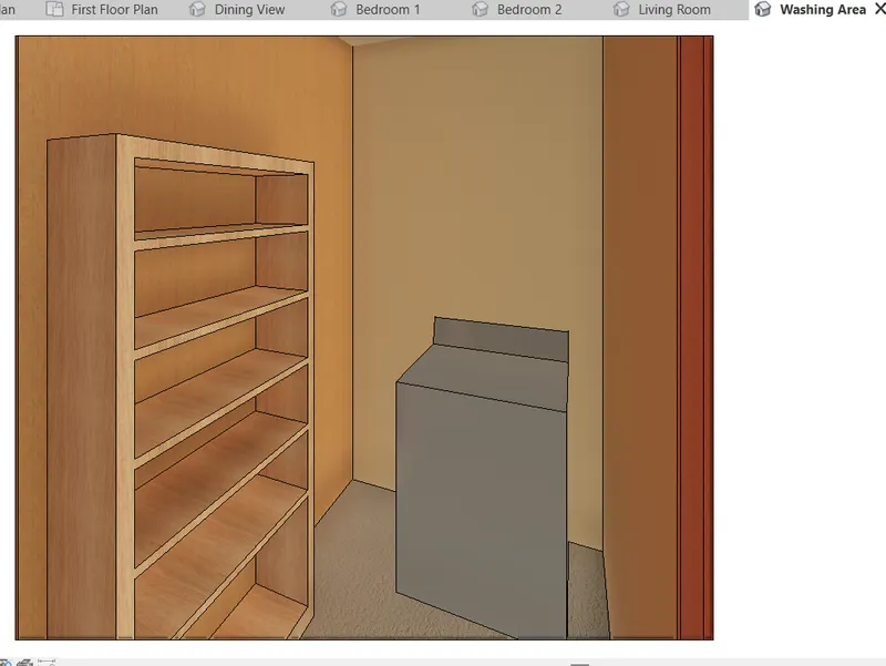
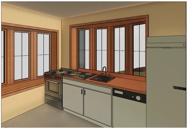
To create a camera specific view or 3D view of each room and also at them to the sheets.
INTRODUCTION :-
Revit is a commercial building information modeling (BIM) software by the company Autodesk.It’s generally used by architects, structural engineers, mechanical, electrical, and plumbing (MEP) engineers, designers, and contractors. Autodesk Revit allows users to create, edit, and review 3D models in exceptional detail.
PROCEDURE :-
Open the project file and then click on the home option that is available on the top of the toolbars
And then select the camera option
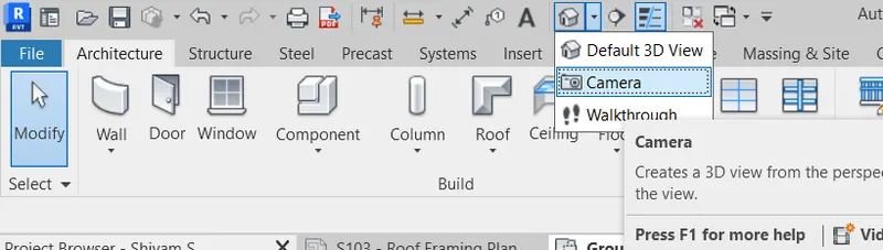
Then place the camera as per your requirement and then provide the specific view of the room
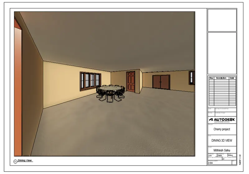
a.Dining view
b.Bedroom 1 view
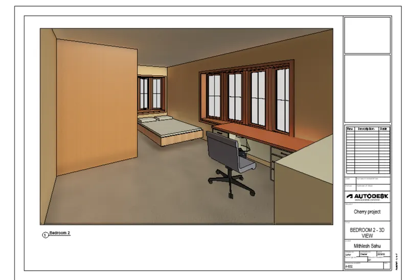
c.Bedroom 2 view
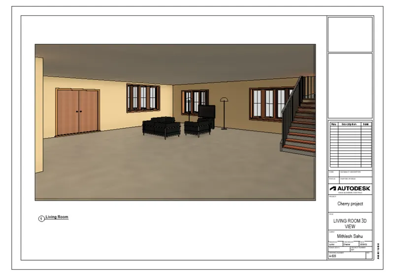
d.Living room view
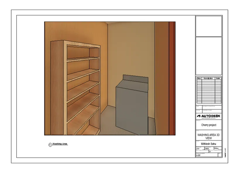
e.Washing area view:-
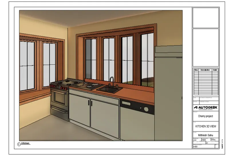
f.Kitchen view :-
Now to add them to the sheet
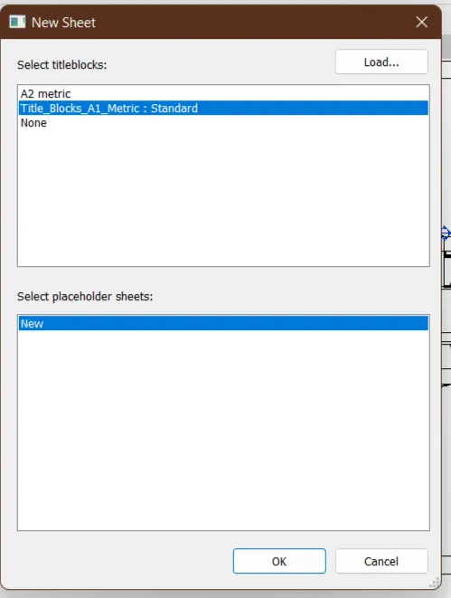
Go to the view tab and then click on the sheet option
Dialogue box will open
Select the required sheet and then click ok
Place the sheets as per the requirement or you can adjust them also but they sing the scale of the views.
Created sheets have been renamed and attached below
A501 - BEDROOM 1 3D VIEW
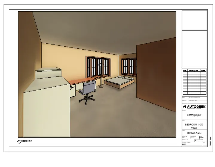
A502 - BEDROOM 2 3D VIEW
A-503 - KITCHEN 3D VIEW
A-504 - DINING 3D VIEW
A-505-LIVING ROOM 3D VIEW
A-506- WASHING AREA 3D VIEW
RESULT :-
Hence different views have been created using the camera option and they are also attached to the sheets and attached to the file