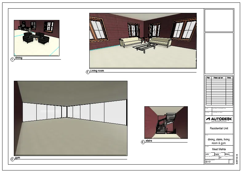
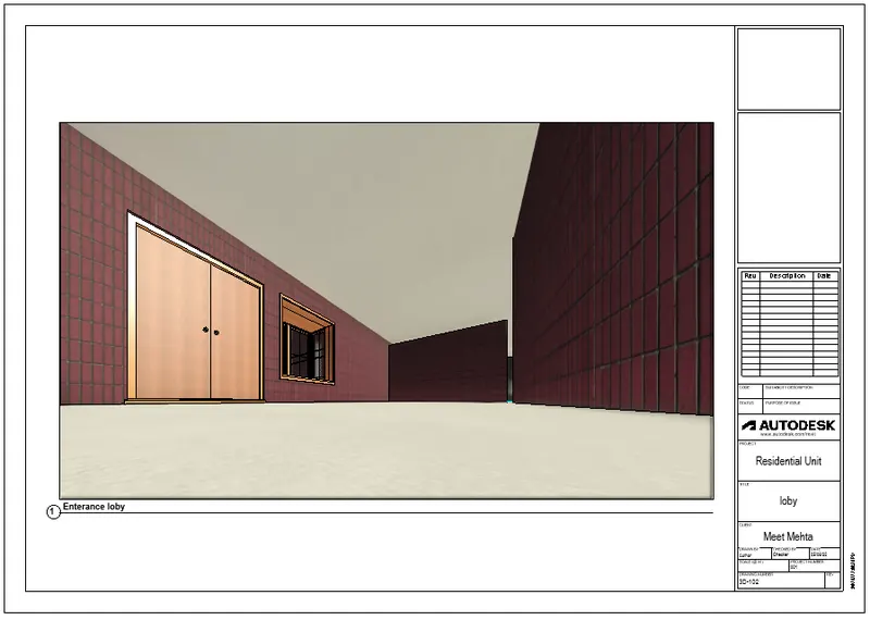
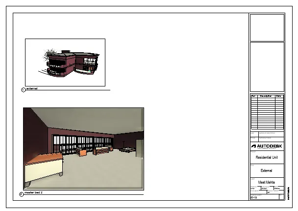
3D Creation of Celing, Roof, Architectural plan, Structural plan, Sectional view, Elevation view and Camera specific view for a house plan using REVIT
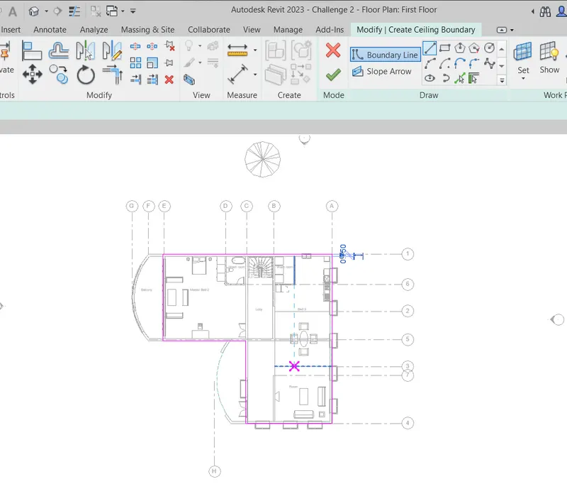
AIM_1: Based on the project saved from Week 3, proceed from the First Floor Level. Model a Ceiling from the architecture tab above the walls at the first-floor level
INTRODUCTION: In the following question the student is asked to work on the main aim of creating a ceiling for the different floors of the building. The ceiling is to be created in the same project which was created in week 3. Please have a look at the below procedure and snips for more clarity.
PROCEDURE:
- Open the week 3 challenge file in Revit.
- In the architecture menu, click on the option to create a ceiling, just beside the floor creating an icon.
- Now create the boundary on which the user wants the ceiling to be created.
- Press enter and the ceiling is created.
- Now follow the same steps and create the ceilings wherever required.
- Please have a look at the below snips for more clarity.
RESULT: A ceiling at desired level can be created.
SNIPS:
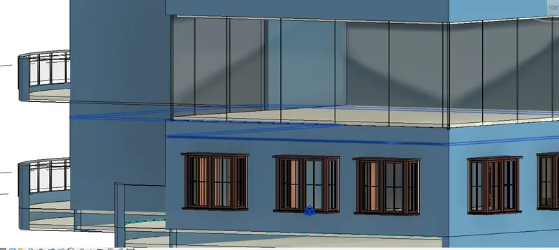
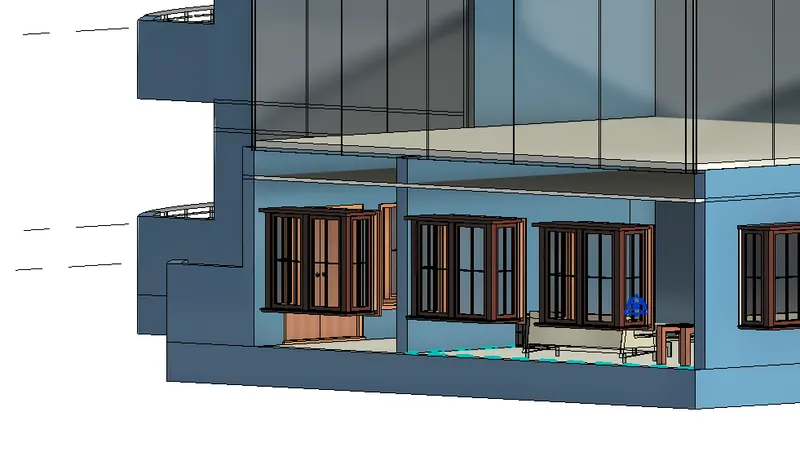
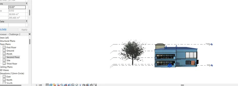
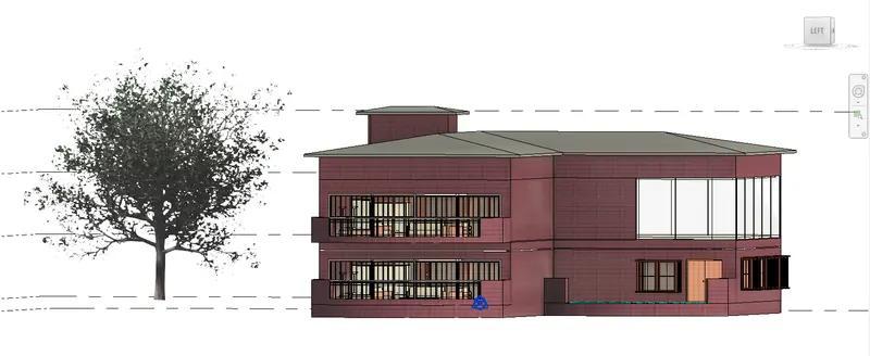
AIM_2: Model a roof above the ceiling by selecting the footprints of the ceiling. Using the adjustment toolbars appearing on-screen adjust the roof slope to 10 degrees
INTRODUCTION: In the following question the student is asked to work on the main aim of creating a roof on the footprints of the ceiling. Please have a look at the below procedure and snips for more clarity.
PROCEDURE:
- Open the second-floor plan.
- Now click on the roof icon in the architecture menu.
- Create the boundary you want the roof on.
- Here I have added roofs on two different structures.
- The offset of 2 feet was given while creating the roof boundary using the rectangular option.
- Click on the green tick and your roof is created.
- Now change the properties of the roof from the properties bar.
- Click on the drop-down list and change the roof type to a generic 4" roof.
- In the property, change the degree of slope from 30 to 10.
- Please have a look at the below snips for more clarity.
RESULT: A roof with a slope of 10 degrees is created on the footprints of the ceiling.
SNIPS:
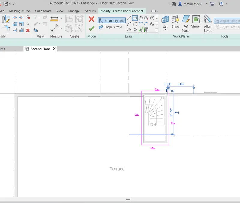
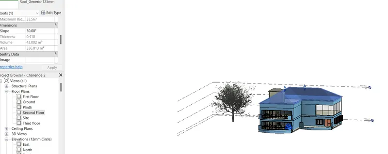
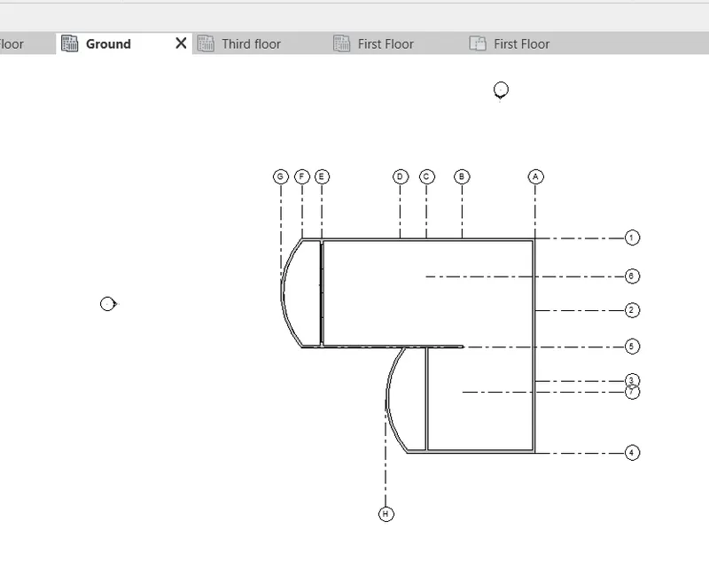
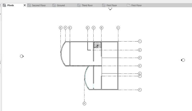
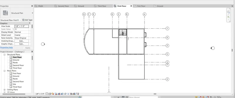
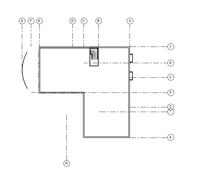
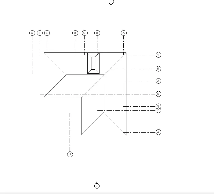
AIM_3: Using the file saved from weeks 2 to 4, create plan views for ground floor level and first-floor level including all the walls, floors, and components. Separate them into
architecture and structural plans
a. Architecture plan must have walls, floors, and all the components placed within the building
b. The structure plan must have details of only walls, floors, and columns
INTRODUCTION: In the following question the student is asked to work on the main aim of creating plan views for all architectural and structural floor plans of the residential unit. Please have a look at the below procedure and snips for more clarity.
PROCEDURE:
- In the existing file, open the view bar.
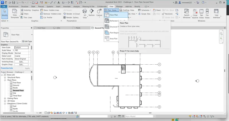
- In that click on the plan view and then select floor plan.
- An option will be asked whether to create or load a new template.
- Select the standard template and then a dialog box pops up.
- In that select the floor plan you like to create.
- As Revit creates the floor plans on its own, no need to create architectural floor plans.
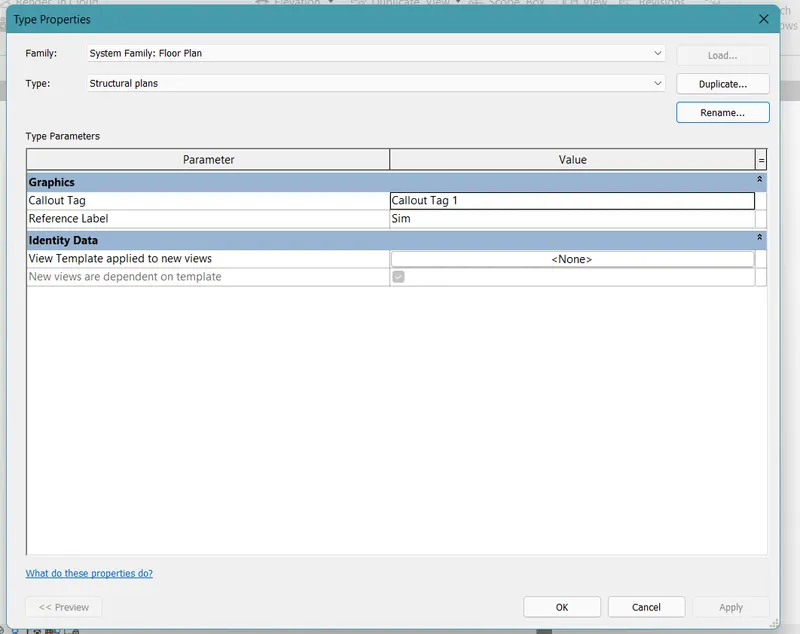
- Now again select the plan view option and then click on the structural plan option.
- Create a duplicate and name it structural plans.
- Now create different plans for all the floors and roofs.
- Please have a look at the below snips for more clarity.
RESULT: Different Architectural and structural plan views of all the floors and roofs are created.
SNIPS:
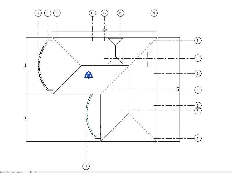
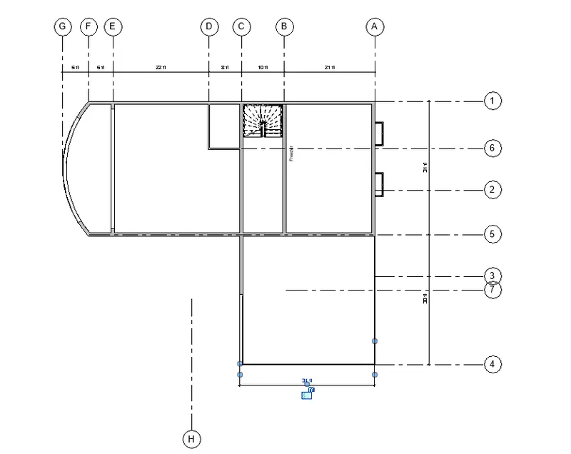
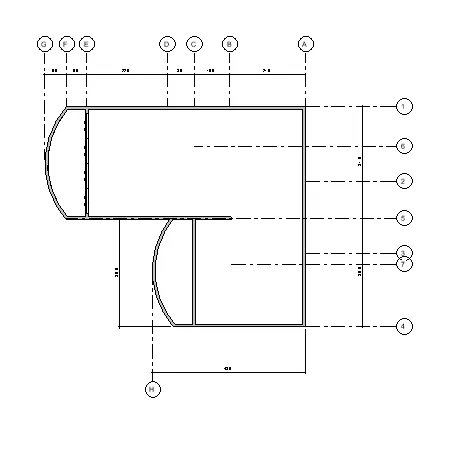
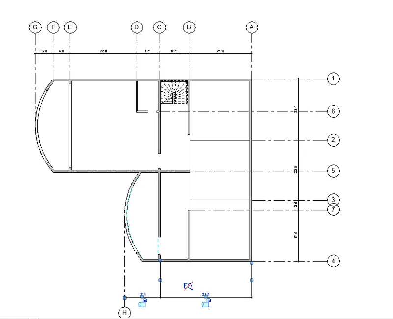
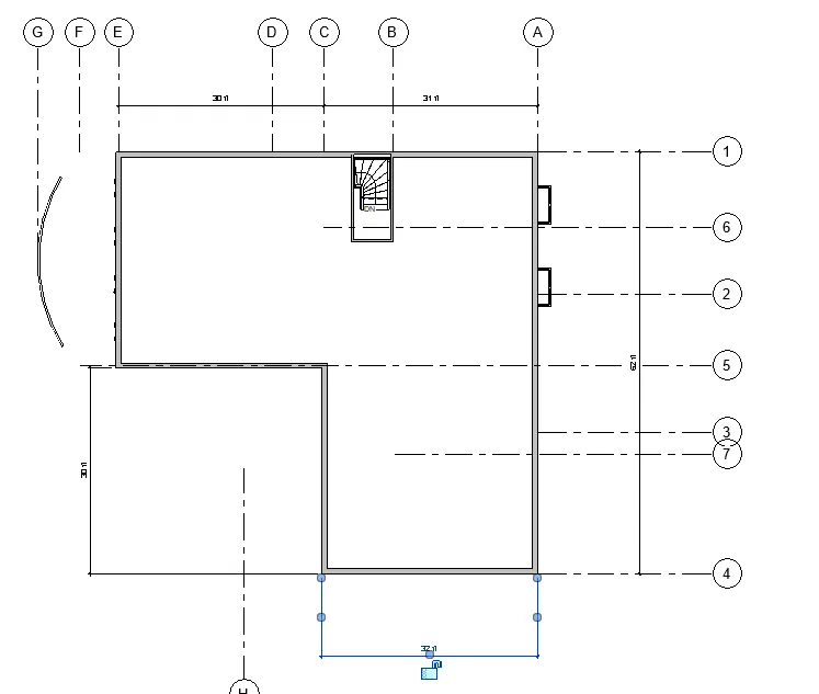
AIM_4: Using annotate toolbar add dimensions to all the walls and floors concerning the longitudinal and transverse grids created in the project file
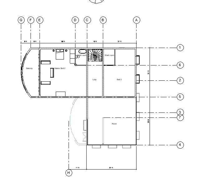
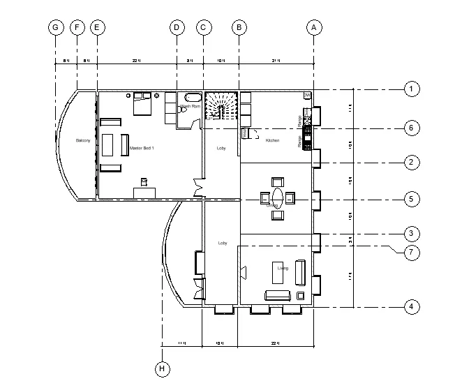
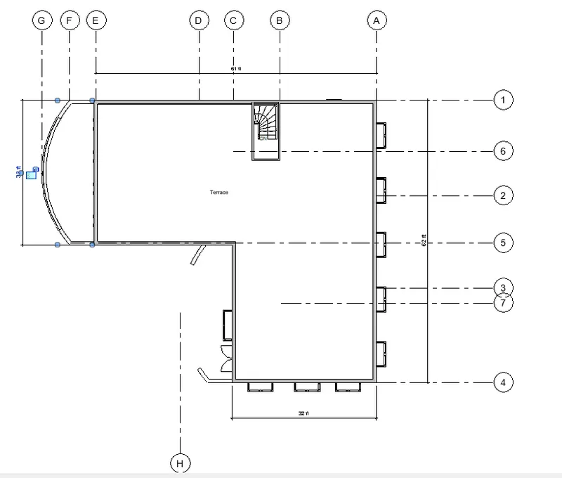
a. The architecture plan dimensions include details on where the components are placed within the buildings about grids. Overall dimensions are sufficient for architecture plans
b. The Structure plan dimensions must include details on the position of all the walls and interior walls concerning grids. Locate all the framing components of the building regarding a fixed point using Structural plans
INTRODUCTION: In the following question the student is asked to work on the main aim of adding the annotations to both architectural and structural plan views w.r.t. the grids. Please have a look at the below procedure and snips for more clarity.
PROCEDURE:
- Open any architectural or structural floor plan.
- Start dimensioning operation by typing DI on the keyboard to enable the command.
- Now give dimensions wherever required.
- Repeat the above steps to all the sheets.
- Please have a look at the below snips for more clarity.
RESULT: Dimensions were added w.r.t. the grids created to all the structural and architectural plans.
SNIPS:
AIM_5: Create a sheet template from the view tab and adjust the parameters on the sheet to add appropriate views
INTRODUCTION: In the following question the student is asked to work on the main aim of creating a sheet template and adjusting its parameters on the sheet to add appropriate views. Please have a look at the below procedure and snips for more clarity.
PROCEDURE:
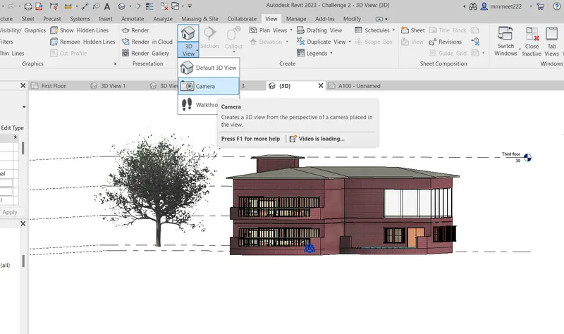
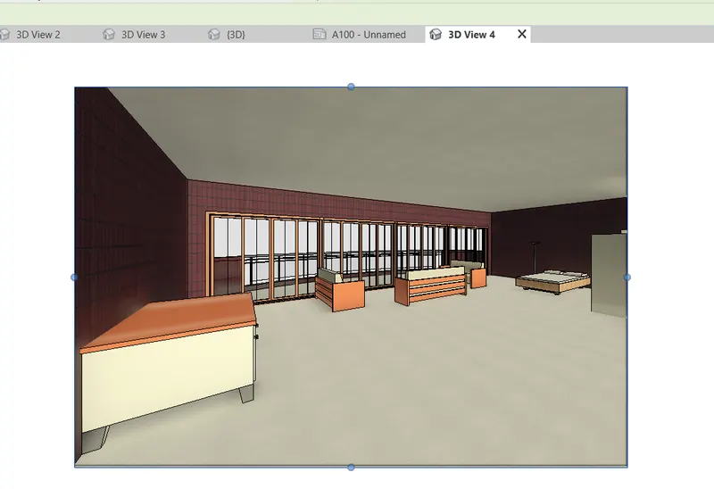
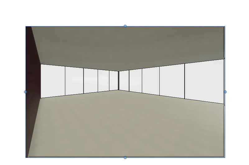
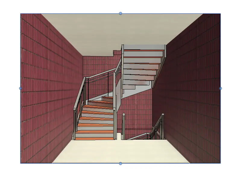
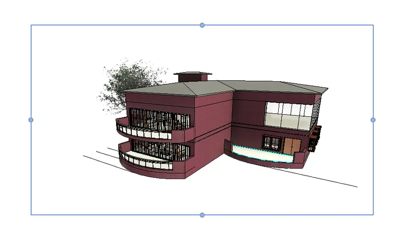
- Open the View menu and then create different views by keeping the camera in different positions on different floors and different rooms of the residential unit.
- Save those views with different names.
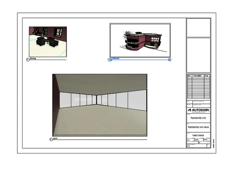
- Now in the view menu click on the sheet option.
- A sheet o[ens up.
- Add the parameters to the sheet as the user wishes.
- Then drag a view from the project browser to the sheet and arrange it as required in the sheet.
- Please have a look at the below snips for more clarity.
RESULT: The parameter of the sheet were adjusted and a sheet was formed having different views of the residential unit.
SNIPS:
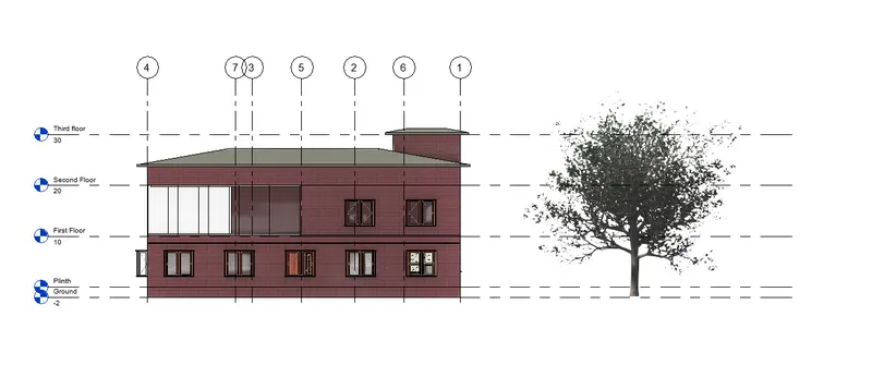
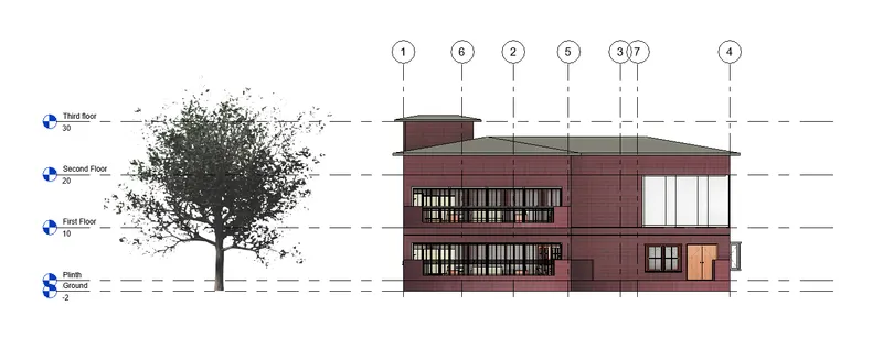
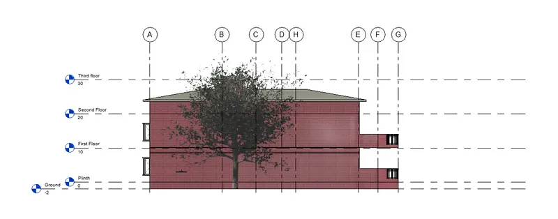
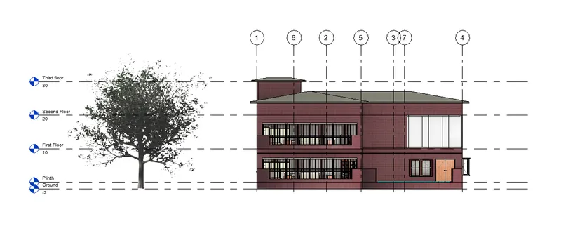
AIM_6: Using the elevation tab create the elevation views, looking at your building from East, North, South, and West
INTRODUCTION: In the following question the student is asked to work on the main aim of creating elevations in all the four directions, i.e., North, South, East, and West. Please have a look at the below procedure and snips for more clarity.
PROCEDURE:
- Normally, Revit has priorly created 4 different elevations in the project browser under the elevation section.
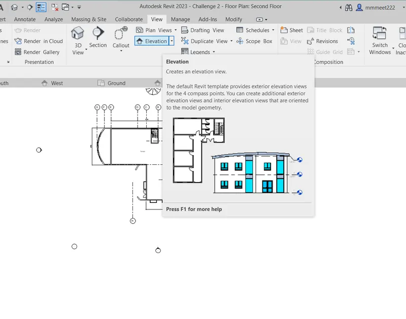
- But if they are not there then one can create it from the view menu by clicking on the elevation option.
- Click the elevation option a box will appear.
- Position that box at the place from where the user wants to see the elevation from.
- Create such different elevations in all four directions and rename them North, South, East, and West.
- Please have a look at the below snips for more clarity.
RESULT: Different elevations of the residential unit were created in different directions.
SNIPS:
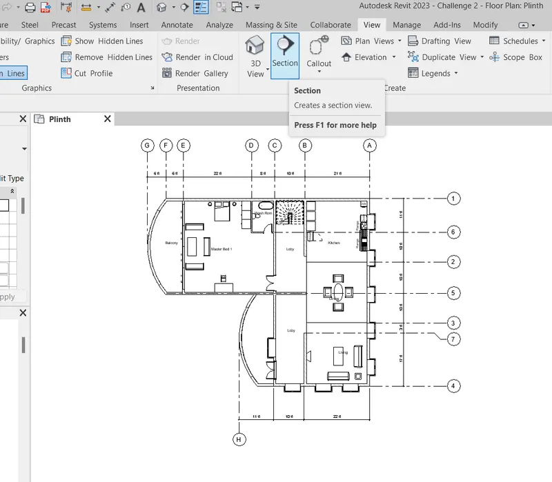
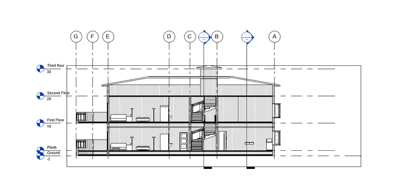
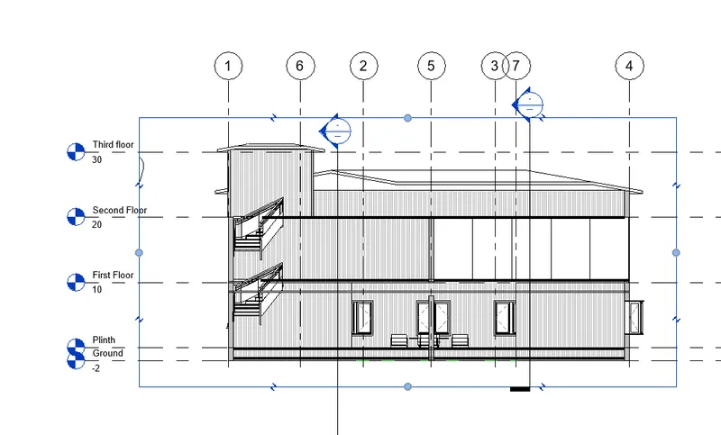
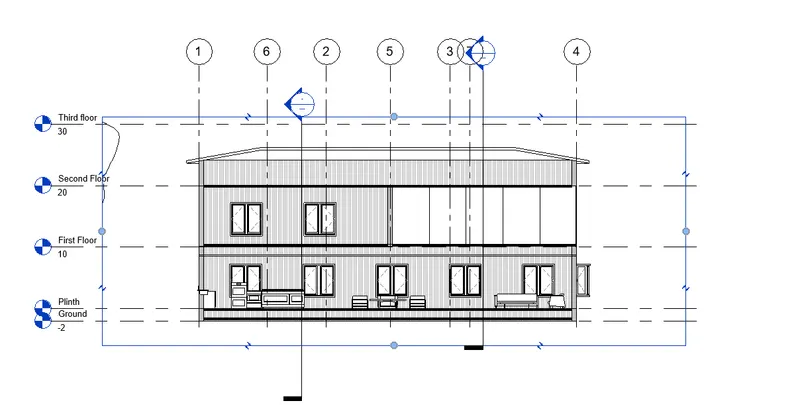
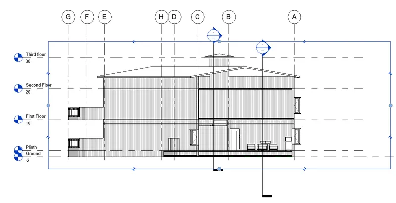
AIM_7: Produce section cut through each room either cutting across longitudinally or in a transverse direction
INTRODUCTION: In the following question the student is asked to work on the main aim of creating a section of each room. Please have a look at the below procedure and snips for more clarity.
PROCEDURE:
- In the View menu click on the section icon.
- Now give the line and direction of the place, where the user wants the section.
- Create different such sections and rename them.
- Now adjust the length and height of the sections and save them.
- Please have a look at the below snips for more clarity.
RESULT: Sections of the different rooms were created.
SNIPS:
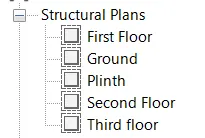
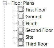
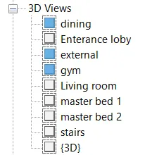
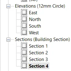
AIM_8: Classify the views, Plan Views, Section Views, and Elevation views to either Design or Documentation category using the Properties browser
INTRODUCTION: In the following question the student is asked to work on the main aim of just clarifying and differentiating the different sections in the project browser. Please have a look at the below procedure and snips for more clarity.
PROCEDURE:
- In the ongoing project, there is a project browser in the bottom left of the screen.
- There are different sections for all.
- Click the snips of all different sections, such as floor plans, structural plans, elevations, views, etc.
- Please have a look at the below snips for more clarity.
SNIPS:
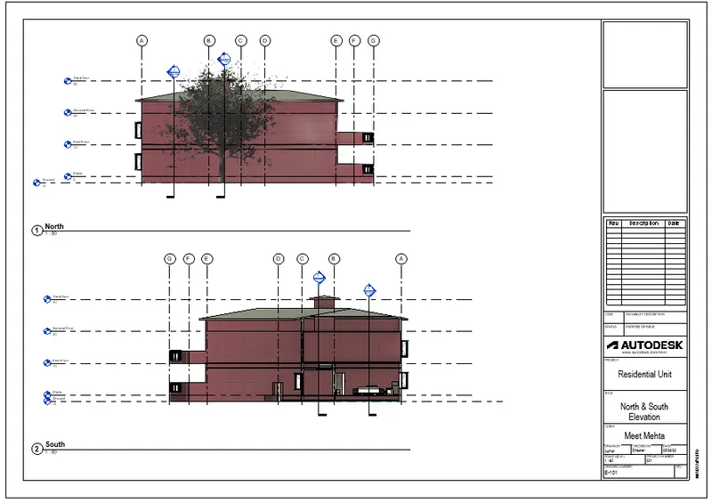
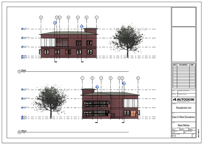
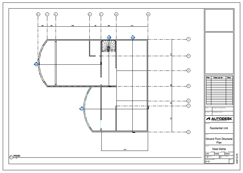
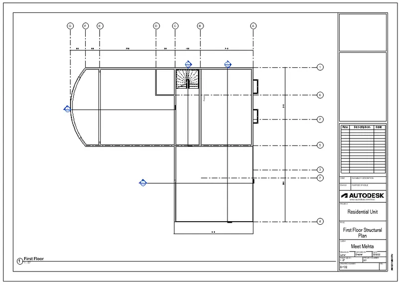
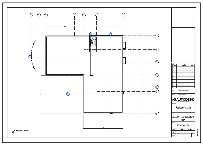
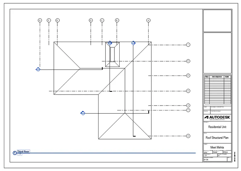
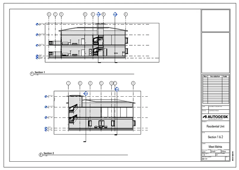
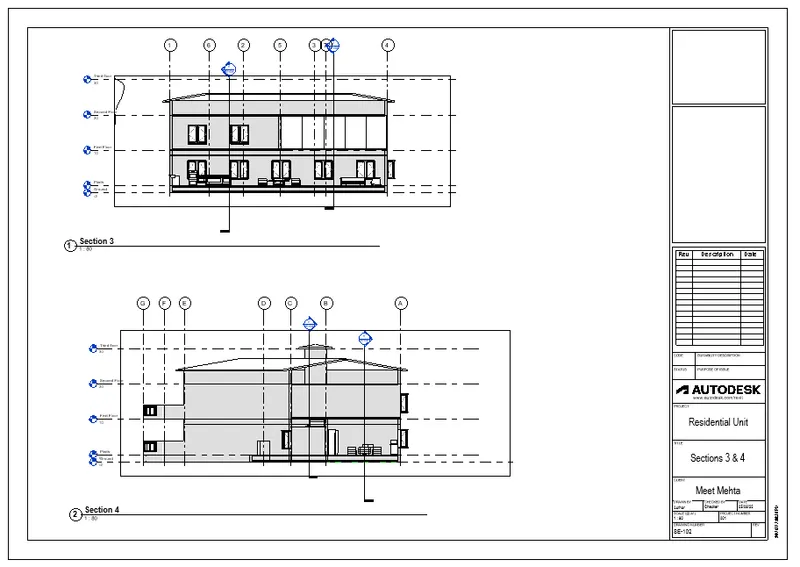
AIM_9: Using the sheet template produced create multiple sheets as follows
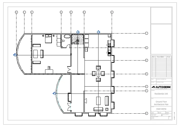
a. A 101- Ground Floor Architecture Plan
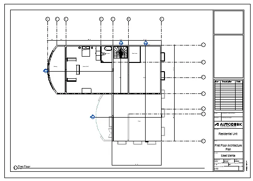
b. A 102- First Floor Architecture Plan
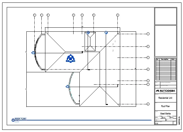
c. A 103- Roof Plan
d. S 101- Ground Floor Structural Plan
e. S 102- First Floor Structural Plan
f. S 103- Roof Framing Plan
g. A-201- North-South Elevations
h. A-202- East-West Elevations
Add additional sheets based on the sections created in your Revit file
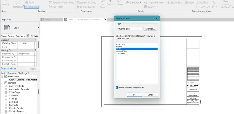
INTRODUCTION: In the following question the student is asked to work on the main aim of creating different sheets for all the floor plans, structural plans, elevations, sections, and views. Please have a look at the below procedure and snips for more clarity.
PROCEDURE:
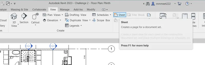
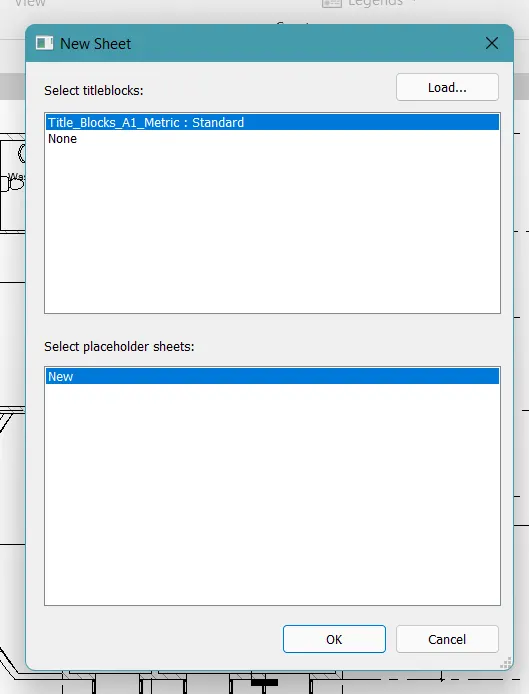
- In the view menu click on the sheet and create a new sheet.
- Now rename the sheet as asked in the question.
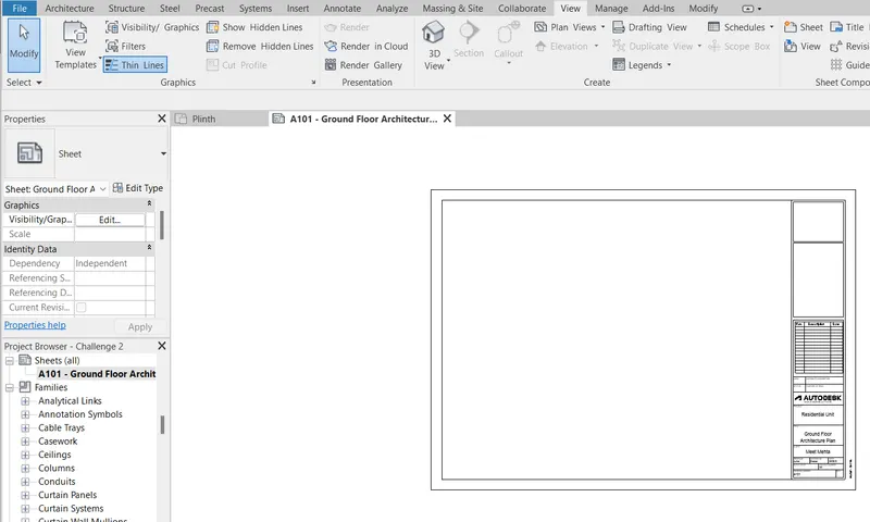
- For example, rename first as A-101 Ground floor architectural plan.
- Now drag the plan view from the floor plan section in the project browser to this sheet.
- Adjust the scale of the view and thus create the sheet.
- Follow the same above steps and create different sheets for all the architectural and structural plans, 3D Views, elevations, etc.
- Please have a look at the below snips for more clarity.
RESULT: Different types of sheets were created.
SNIPS:
AIM_10: Create a camera-specific view or a 3D view in each room ( living, dining, bedroom). Based on the views create a new set of sheets starting A-501 (you can add as many sheets after, 502, 503.. n)to place the 3D view images. Produce the sheets as a part of project drafting.
INTRODUCTION: In the following question the student is asked to work on the main aim of Please have a look at the below procedure and snips for more clarity.
PROCEDURE:
- Open the View menu and then create different views by keeping the camera in different positions on different floors and different rooms of the residential unit.
- Save those views with different names.
- Now in the view menu click on the sheet option.
- A sheet o[ens up.
- Add the parameters to the sheet as the user wishes.
- Then drag a view from the project browser to the sheet and arrange it as required in the sheet.
- Please have a look at the below snips for more clarity.
RESULT: The parameter of the sheet were adjusted and a sheet was formed having different views of the residential unit.
SNIPS: