3D Creation of Celing, Roof, Architectural plan, Structural plan, Sectional view, Elevation view and Camera specific view for a house plan using REVIT
1. Based on the project saved from Week 3, Modeling a Ceiling from the architecture tab above the walls at the first-floor level :
AIM :
To Create a Ceiling above the walls at the first-floor level of the project saved from Week 3.
INTRODUCTION :
- In Revit, we can create the 2D layout and 3D model of the building.
- Here, we can add the architectural elements such as FLOORS, WALLS, DOORS, WINDOWS and other architectural elements with desired colors, types and dimensions.
- We can also convert the 2D layout to the 3D Model by changing it into the Default 3D view.
- Like we discussed before, we can make LEVEL LINES such as Ground floor level, First floor level etc and the GRID LINES for the building models.
- We can also make the created 3D model into the various visual styles as desired, the visual styles such as 2D wireframe, shaded, conceptual, Realistic etc.
- The view cube plays the major in the 3D modelling of the buildings, because it helps to see the created model in all the 360 degree angles.
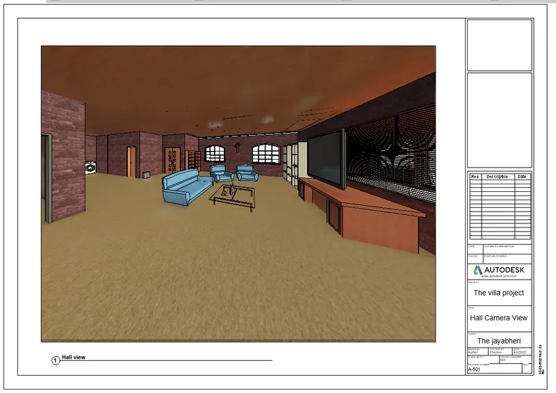
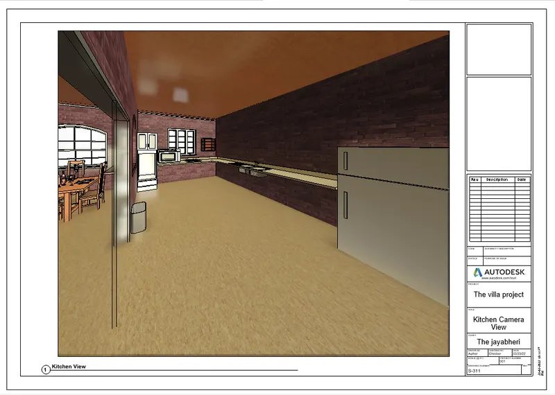
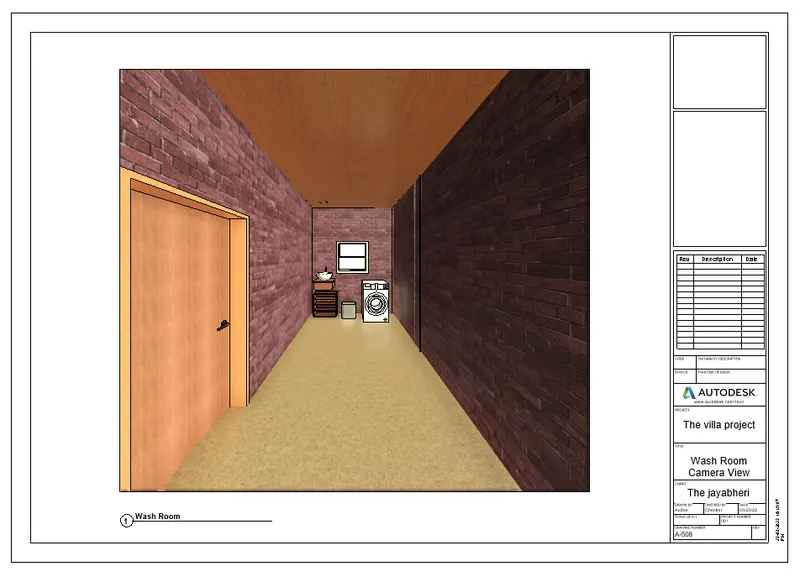
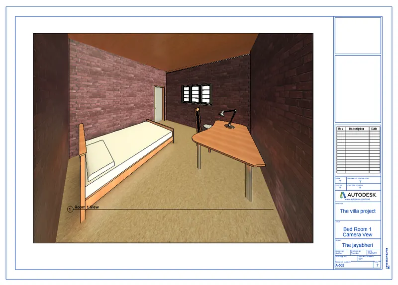
- In revit we can see the rooms created inside the 3D model from the paricular hight and angle with the help of CAMERA tool in the view tool bar.
- The main TWO TABS which are used to CREATE and EDIT the 3D models are "Project browser" and "Properties" .
PROCEDURE:
- First the LEVELS of the building should be created from "Ground level" to the "roof level" before starting of the building layout.
- Before start creating the layout of the building, the Units of the project should be set as per the project requirements.
- The setting of the units are done by selecting MANAGE TAB < PROJECT UNITS and by selecting appropriate units as required.
- Then the layout should be start to create from the Ground level by creating the FLOOR of 4" with the floor creating tool of the dimension of 40' x 60'.
- Followed by the walls are created above the floor , by selecting ARCHITECTURE TAB< WALL and mentioning the wall height as 10' and wall offset as 9" for exterior wall.
- After creating the Exterior wall, the Interior walls (partition walls) are needs to be created with the offset values of 4.5" as desired sizes of rooms needed inside the bluiding.
- Then the AREAS of the rooms should be tagged with the help of the ROOM TAG tool from the ARCHITECTURE TAB < ROOM or AREA.
- By picking the area inside the room, the area of the room will be tagged along with inner area and the name or details of the ROOMS can be edited as desired .
- Then the Doors and Windows are then allowed to add in the walls upto a certain height such as the WINDOWS are need to be placed over the sill level means at the height of 3' from the floor level.
- Likwise the DOORS are needs to be placed over floor level to the lintel level means upto 7', the height and the width of the doors varies depend upon the requirement of the places.
- The MAIN DOOR placed in the entrance are 4' x 7', DOORS used for the rooms are 3' x 7' and the Doors used for the Rest rooms are 2'6" x 7'.
- Likewise the WINDOWS height and widths are varies as desired, these DOORS and WINDOWS are selected and placed in wall by clicking the walls.
- The "Doors" are added to the created layout, by selecting the "ARCHITECTURE TAB" in the tool bar and select Door < Load family < US < Door (family).
- Likewise the "Windows" are added to the created layout, by select the "ARCHITECTURE TAB" in the tool bar and select Windows < Load family < US < Window (family).
- After loading the required DOORS and WINDOWS, it is inserted inside the file from ARCHITECTURE TAB < COMPONENT < PLACE COMPONENT.
- Followed by the DOORS and WINDOWS, the " Furnitures " are need to be loaded and placed at the required place.
- The "Furnitures" are added into the created layout, by selecting the "ARCHITECTURE TAB" in the tool bar and select Component < Load family < US < Furnitures (family).
- Then the PLUMBING FIXTURES and the WATER CLOSETS are addded at the desired places such as REST ROOMS and KITCHEN or as required.
- Likewise all the ELEMENTS are placed or added inside the building model from the COMPONENT TOOL from the ARCHITECTURE TAB and placing it in the desired places.
- Here the ceiling is starts to be created at the First floor level from the CEILING Option in the Architectural Tab at the offset of 10' from ground level.
- Then the Created Ground floor will be copied and pasted over the First floor level, after coping the Ground floor model PASTE < PLACE AT THE LEVEL SELECTED.
- Before start pasting, make sure that the First floor level line is selected.
- Followed by, the Roof of the First floor model should be created by changing the 3D model to the 2D layout and clicking the Roof plan view from the PROJECT BROWSER, then the roof will be created over the exterior walls.
- We can view the interiors of the building by fixing the CAMERA inside the 3D model and saving the view as desired name and view whenever required.
- It is done by VIEW TAB < 3D VIEW < CAMERA .
RESULT :
- Here in the result we can see the CEILING is created over the First floor level at the offset of 10' from the ground level.
- Also can see the different types of architectural elements are created in the model.
- The architectural elements such as WALLS, DOORS and WINDOWS are attached in the created layout.
- The various types of elements have been attached from different families and categories with desired dimensions as required.
- The thickness of the Exterior walls are 9" and the Interior walls are 4.5".
- The area of the total 3D model of this residential building created was 40' x 60'.
- The thickness of the Floors and the Roof are 4".
2. Model a roof above the ceiling by selecting the footprints of the ceiling and adjust the roof slope to 10 degrees :
AIM :
To Create a Model of a roof above the ceiling by selecting the footprints of the ceiling by adjusting the roof slope to 10 degrees.
INTRODUCTION :
- In Revit, we can create the 2D layout and 3D model of the building.
- Here, we can add the architectural elements such as FLOORS, WALLS, DOORS, WINDOWS and other architectural elements with desired colors, types and dimensions.
- We can also convert the 2D layout to the 3D Model by changing it into the Default 3D view.
- Like we discussed before, we can make LEVEL LINES such as Ground floor level, First floor level etc and the GRID LINES for the building models.
- We can also make the created 3D model into the various visual styles as desired, the visual styles such as 2D wireframe, shaded, conceptual, Realistic etc.
- The view cube plays the major in the 3D modelling of the buildings, because it helps to see the created model in all the 360 degree angles.
- In revit we can see the rooms created inside the 3D model from the paricular hight and angle with the help of CAMERA tool in the view tool bar.
- The main TWO TABS which are used to CREATE and EDIT the 3D models are "Project browser" and "Properties" .
PROCEDURE:
- First the LEVELS of the building should be created from "Ground level" to the "roof level" before starting of the building layout.
- Before start creating the layout of the building, the Units of the project should be set as per the project requirements.
- The setting of the units are done by selecting MANAGE TAB < PROJECT UNITS and by selecting appropriate units as required.
- Then the layout should be start to create from the Ground level by creating the FLOOR of 4" with the floor creating tool of the dimension of 40' x 60'.
- Followed by the walls are created above the floor , by selecting ARCHITECTURE TAB< WALL and mentioning the wall height as 10' and wall offset as 9" for exterior wall.
- After creating the Exterior wall, the Interior walls (partition walls) are needs to be created with the offset values of 4.5" as desired sizes of rooms needed inside the bluiding.
- Then the AREAS of the rooms should be tagged with the help of the ROOM TAG tool from the ARCHITECTURE TAB < ROOM or AREA.
- By picking the area inside the room, the area of the room will be tagged along with inner area and the name or details of the ROOMS can be edited as desired .
- Then the Doors and Windows are then allowed to add in the walls upto a certain height such as the WINDOWS are need to be placed over the sill level means at the height of 3' from the floor level.
- Likwise the DOORS are needs to be placed over floor level to the lintel level means upto 7', the height and the width of the doors varies depend upon the requirement of the places.
- The MAIN DOOR placed in the entrance are 4' x 7', DOORS used for the rooms are 3' x 7' and the Doors used for the Rest rooms are 2'6" x 7'.
- Likewise the WINDOWS height and widths are varies as desired, these DOORS and WINDOWS are selected and placed in wall by clicking the walls.
- The "Doors" are added to the created layout, by selecting the "ARCHITECTURE TAB" in the tool bar and select Door < Load family < US < Door (family).
- Likewise the "Windows" are added to the created layout, by select the "ARCHITECTURE TAB" in the tool bar and select Windows < Load family < US < Window (family).
- After loading the required DOORS and WINDOWS, it is inserted inside the file from ARCHITECTURE TAB < COMPONENT < PLACE COMPONENT.
- Followed by the DOORS and WINDOWS, the " Furnitures " are need to be loaded and placed at the required place.
- The "Furnitures" are added into the created layout, by selecting the "ARCHITECTURE TAB" in the tool bar and select Component < Load family < US < Furnitures (family).
- Then the PLUMBING FIXTURES and the WATER CLOSETS are addded at the desired places such as REST ROOMS and KITCHEN or as required.
- Likewise all the ELEMENTS are placed or added inside the building model from the COMPONENT TOOL from the ARCHITECTURE TAB and placing it in the desired places.
- Here the ceiling is starts to be created at the First floor level from the CEILING Option in the Architectural Tab at the offset of 10' from ground level.
- And over the Ceiling, the roof from the ARCHITECTURE TAB<ROOF
- The Roof created should be having a slope of 10 Degree as Required and it can be adjusted by changing its slope value from the Properties Browser.
- Then the Created Ground floor will be copied and pasted over the First floor level, after coping the Ground floor model PASTE < PLACE AT THE LEVEL SELECTED.
- Before start pasting, make sure that the First floor level line is selected.
- Followed by, the Roof of the First floor model should be created by changing the 3D model to the 2D layout and clicking the Roof plan view from the PROJECT BROWSER, then the roof will be created over the exterior walls.
- We can view the interiors of the building by fixing the CAMERA inside the 3D model and saving the view as desired name and view whenever required.
- It is done by VIEW TAB < 3D VIEW < CAMERA .
RESULT :
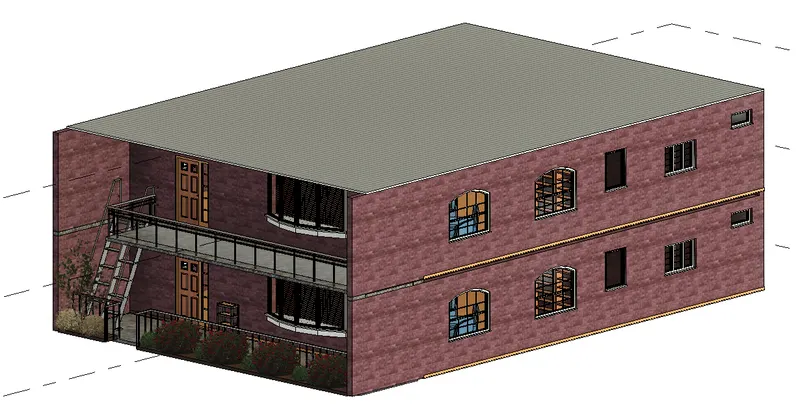
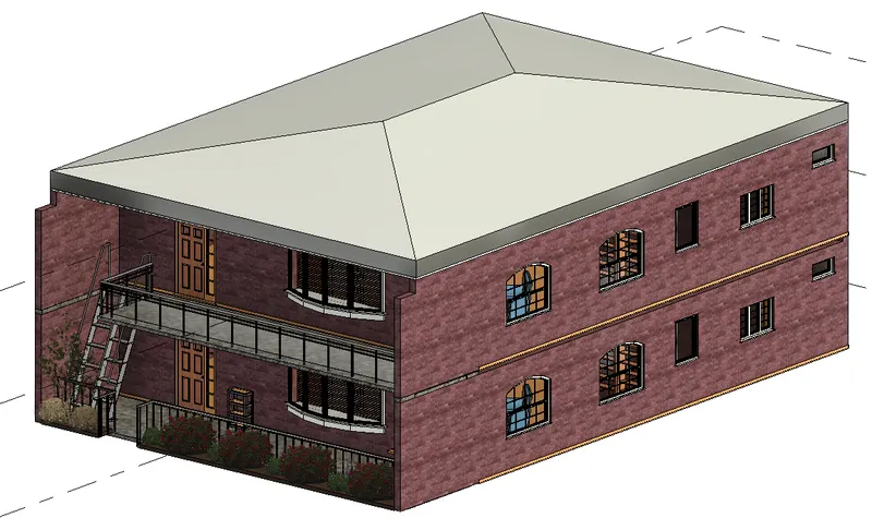
- Here in the result we can see the Roof created at the First floor level with the slope value of 10 Degree.
- Aslo can see the different types of architectural elements are created in the below model.
- The architectural elements such as WALLS, DOORS and WINDOWS are attached in the created layout.
- The various types of elements have been attached from different families and categories with desired dimensions as required.
- The created Ground floor with walls are copied and pasted at the First floor level along with its components.
- The thickness of the Exterior walls are 9" and the Interior walls are 4.5".
- The area of the total 3D model of this residential building created was 40' x 60'.
- The thickness of the Floors and the Roof are 4".
3. Using the file saved from weeks 2 to 4, create plan views including all the walls, floors, and components and Separating them to architecture and structural plans :
AIM :
To Create a Ceiling above the walls at the first-floor level of the project saved from Week 3.
INTRODUCTION :
- In Revit, we can create the 2D layout and 3D model of the building.
- Here, we can add the architectural elements such as FLOORS, WALLS, DOORS, WINDOWS and other architectural elements with desired colors, types and dimensions.
- We can also convert the 2D layout to the 3D Model by changing it into the Default 3D view.
- Like we discussed before, we can make LEVEL LINES such as Ground floor level, First floor level etc and the GRID LINES for the building models.
- We can also make the created 3D model into the various visual styles as desired, the visual styles such as 2D wireframe, shaded, conceptual, Realistic etc.
- The view cube plays the major in the 3D modelling of the buildings, because it helps to see the created model in all the 360 degree angles.
- In revit we can see the rooms created inside the 3D model from the paricular hight and angle with the help of CAMERA tool in the view tool bar.
- The main TWO TABS which are used to CREATE and EDIT the 3D models are "Project browser" and "Properties" .
PROCEDURE:
- First the LEVELS of the building should be created from "Ground level" to the "roof level" before starting of the building layout.
- Before start creating the layout of the building, the Units of the project should be set as per the project requirements.
- The setting of the units are done by selecting MANAGE TAB < PROJECT UNITS and by selecting appropriate units as required.
- Then the layout should be start to create from the Ground level by creating the FLOOR of 4" with the floor creating tool of the dimension of 40' x 60'.
- Followed by the walls are created above the floor , by selecting ARCHITECTURE TAB< WALL and mentioning the wall height as 10' and wall offset as 9" for exterior wall.
- After creating the Exterior wall, the Interior walls (partition walls) are needs to be created with the offset values of 4.5" as desired sizes of rooms needed inside the bluiding.
- Then the AREAS of the rooms should be tagged with the help of the ROOM TAG tool from the ARCHITECTURE TAB < ROOM or AREA.
- By picking the area inside the room, the area of the room will be tagged along with inner area and the name or details of the ROOMS can be edited as desired .
- Then the Doors and Windows are then allowed to add in the walls upto a certain height such as the WINDOWS are need to be placed over the sill level means at the height of 3' from the floor level.
- Likwise the DOORS are needs to be placed over floor level to the lintel level means upto 7', the height and the width of the doors varies depend upon the requirement of the places.
- The MAIN DOOR placed in the entrance are 4' x 7', DOORS used for the rooms are 3' x 7' and the Doors used for the Rest rooms are 2'6" x 7'.
- Likewise the WINDOWS height and widths are varies as desired, these DOORS and WINDOWS are selected and placed in wall by clicking the walls.
- The "Doors" are added to the created layout, by selecting the "ARCHITECTURE TAB" in the tool bar and select Door < Load family < US < Door (family).
- Likewise the "Windows" are added to the created layout, by select the "ARCHITECTURE TAB" in the tool bar and select Windows < Load family < US < Window (family).
- After loading the required DOORS and WINDOWS, it is inserted inside the file from ARCHITECTURE TAB < COMPONENT < PLACE COMPONENT.
- Followed by the DOORS and WINDOWS, the " Furnitures " are need to be loaded and placed at the required place.
- The "Furnitures" are added into the created layout, by selecting the "ARCHITECTURE TAB" in the tool bar and select Component < Load family < US < Furnitures (family).
- Then the PLUMBING FIXTURES and the WATER CLOSETS are addded at the desired places such as REST ROOMS and KITCHEN or as required.
- Likewise the all ELEMENTS are placed or added inside the building model from the COMPONENT TOOL from the ARCHITECTURE TAB and placing it in the desired places.
- Then the Created Ground floor will be copied and pasted over the First floor, after coping the Ground floor model PASTE < PLACE AT THE LEVEL SELECTED.
- Before start pasting, make sure that the First floor level line should be selected.
- To create the individual Architectural and Structural Plans as per Required, First we should change the 3D view into the Plan view by selecting the floor plan from the Browser Plan.
- Then from VIEW TAB < PLAN VIEWS < FLOOR PLAN or STRUCTURAL PLAN , we can change the Floor plan into both architectural and structural View as Required.
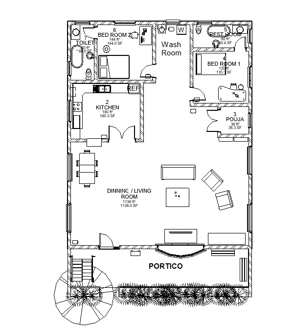
- In Architecture or Floor plan view shows all the components present in the Building plan.
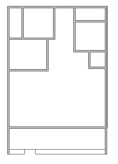
- But in Structural plan view, it shows only the Structural elements present in the Building plan such as Walls, columns, beams etc.
RESULT :
- Here in the result we can see different views of the plans such as both Architectural view and Structural View.
- The architectural elements such as WALLS, DOORS and WINDOWS are attached in the created layout.
- The various types of elements have been attached from different families and categories with desired dimensions as required.
- The created Ground floor with walls are copied and pasted at the First floor level along with its components.
- The thickness of the Exterior walls are 9" and the Interior walls are 4.5".
- The area of the total 3D model of this residential building created was 40' x 60'.
- The thickness of the Floors and the Roof are 4".
a) Architecture plan having walls, floors, and all the components placed within the building :
b) Structure plan having details of only walls, floors, and columns :
4. Using annotate toolbar add dimensions to all the walls and floors with reference to the longitudinal and transverse grids created in the project file :
AIM :
To Create a dimensions to all the walls and floors with reference to the longitudinal and transverse grids created in the project file Ceiling above the walls at the first-floor level of the project saved from Week 3 from the annotation bar.
INTRODUCTION :
- In Revit, we can create the 2D layout and 3D model of the building.
- Here, we can add the architectural elements such as FLOORS, WALLS, DOORS, WINDOWS and other architectural elements with desired colors, types and dimensions.
- We can also convert the 2D layout to the 3D Model by changing it into the Default 3D view.
- Like we discussed before, we can make LEVEL LINES such as Ground floor level, First floor level etc and the GRID LINES for the building models.
- We can also make the created 3D model into the various visual styles as desired, the visual styles such as 2D wireframe, shaded, conceptual, Realistic etc.
- The view cube plays the major in the 3D modelling of the buildings, because it helps to see the created model in all the 360 degree angles.
- In revit we can see the rooms created inside the 3D model from the paricular hight and angle with the help of CAMERA tool in the view tool bar.
- The main TWO TABS which are used to CREATE and EDIT the 3D models are "Project browser" and "Properties" .
PROCEDURE:
- First the LEVELS of the building should be created from "Ground level" to the "roof level" before starting of the building layout.
- Before start creating the layout of the building, the Units of the project should be set as per the project requirements.
- The setting of the units are done by selecting MANAGE TAB < PROJECT UNITS and by selecting appropriate units as required.
- Then the layout should be start to create from the Ground level by creating the FLOOR of 4" with the floor creating tool of the dimension of 40' x 60'.
- Followed by the walls are created above the floor , by selecting ARCHITECTURE TAB< WALL and mentioning the wall height as 10' and wall offset as 9" for exterior wall.
- After creating the Exterior wall, the Interior walls (partition walls) are needs to be created with the offset values of 4.5" as desired sizes of rooms needed inside the bluiding.
- Then the AREAS of the rooms should be tagged with the help of the ROOM TAG tool from the ARCHITECTURE TAB < ROOM or AREA.
- By picking the area inside the room, the area of the room will be tagged along with inner area and the name or details of the ROOMS can be edited as desired .
- Then the Doors and Windows are then allowed to add in the walls upto a certain height such as the WINDOWS are need to be placed over the sill level means at the height of 3' from the floor level.
- Likwise the DOORS are needs to be placed over floor level to the lintel level means upto 7', the height and the width of the doors varies depend upon the requirement of the places.
- The MAIN DOOR placed in the entrance are 4' x 7', DOORS used for the rooms are 3' x 7' and the Doors used for the Rest rooms are 2'6" x 7'.
- Likewise the WINDOWS height and widths are varies as desired, these DOORS and WINDOWS are selected and placed in wall by clicking the walls.
- The "Doors" are added to the created layout, by selecting the "ARCHITECTURE TAB" in the tool bar and select Door < Load family < US < Door (family).
- Likewise the "Windows" are added to the created layout, by select the "ARCHITECTURE TAB" in the tool bar and select Windows < Load family < US < Window (family).
- After loading the required DOORS and WINDOWS, it is inserted inside the file from ARCHITECTURE TAB < COMPONENT < PLACE COMPONENT.
- Followed by the DOORS and WINDOWS, the " Furnitures " are need to be loaded and placed at the required place.
- The "Furnitures" are added into the created layout, by selecting the "ARCHITECTURE TAB" in the tool bar and select Component < Load family < US < Furnitures (family).
- Then the PLUMBING FIXTURES and the WATER CLOSETS are addded at the desired places such as REST ROOMS and KITCHEN or as required.
- Likewise the all ELEMENTS are placed or added inside the building model from the COMPONENT TOOL from the ARCHITECTURE TAB and placing it in the desired places.
- Then the Created Ground floor will be copied and pasted over the First floor, after coping the Ground floor model PASTE < PLACE AT THE LEVEL SELECTED.
- Before start pasting, make sure that the First floor level line should be selected.
- Followed by, the Roof of the First floor model should be created by changing the 3D model to the 2D layout and clicking the Roof plan view from the PROJECT BROWSER, then the roof will be created over the exterior walls.
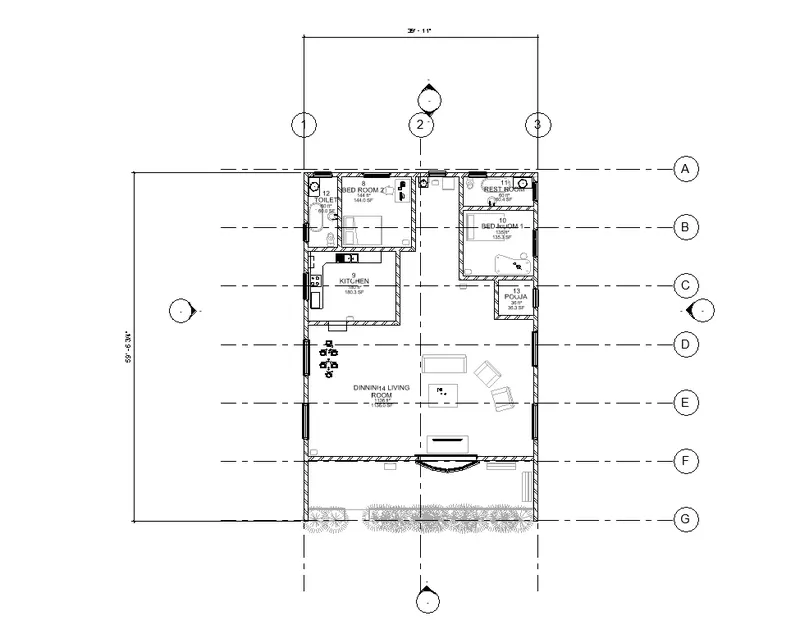
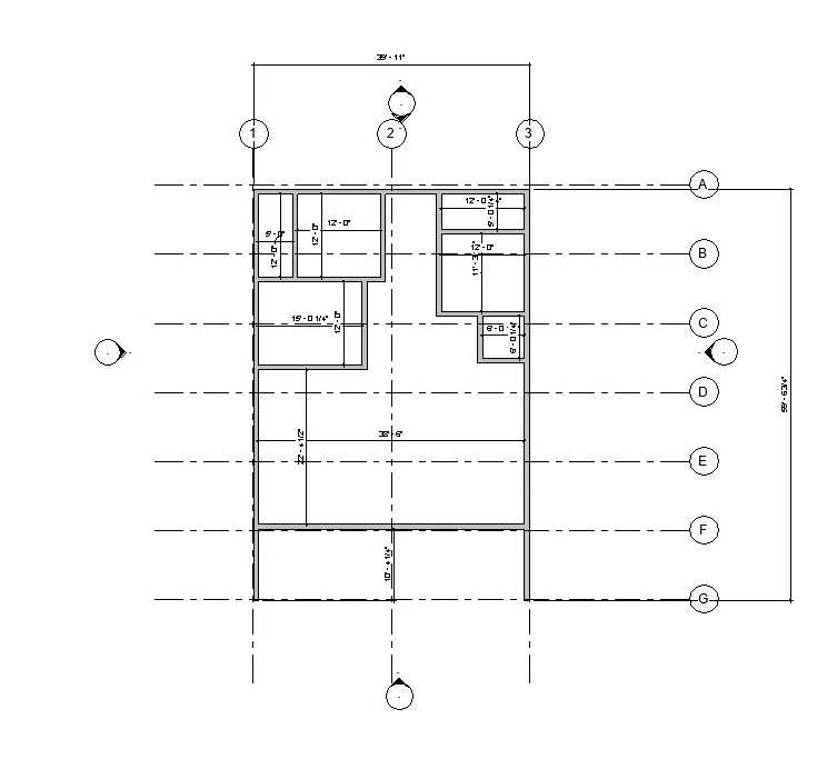
- Then the 3D model should be changed to the Floor plan view and from the ANNOTATE BAR < LINEAR DIMENSION.
- And by selecting floor plan outer areas we can find out and annotate the plan.
RESULT :
- Here in the result we can see the floor both Floor plan and the Structural plan has been Annotated as required.
- Also can see the different types of architectural elements are created in the model.
- The architectural elements such as WALLS, DOORS and WINDOWS are attached in the created layout.
- The various types of elements have been attached from different families and categories with desired dimensions as required.
- The created Ground floor with walls are copied and pasted at the First floor level along with its components.
- The thickness of the Exterior walls are 9" and the Interior walls are 4.5".
- The area of the total 3D model of this residential building created was 40' x 60'.
- The thickness of the Floors and the Roof are 4".
a) The architecture plan dimensions include details on where the components are placed within the buildings with relation to grids :
b ) The Structure plan dimensions must include details on the position of all the walls and interior walls with reference to grids :
5. Create a sheet template from the tab and adjust the parameters on the sheet to add appropriate views :
AIM :
To Create a sheet template from the view tab and adjust the parameters on the sheet to add appropriate views.
INTRODUCTION :
- In Revit, we can create the 2D layout and 3D model of the building.
- Here, we can add the architectural elements such as FLOORS, WALLS, DOORS, WINDOWS and other architectural elements with desired colors, types and dimensions.
- We can also convert the 2D layout to the 3D Model by changing it into the Default 3D view.
- Like we discussed before, we can make LEVEL LINES such as Ground floor level, First floor level etc and the GRID LINES for the building models.
- We can also make the created 3D model into the various visual styles as desired, the visual styles such as 2D wireframe, shaded, conceptual, Realistic etc.
- The view cube plays the major in the 3D modelling of the buildings, because it helps to see the created model in all the 360 degree angles.
- In revit we can see the rooms created inside the 3D model from the paricular hight and angle with the help of CAMERA tool in the view tool bar.
- The main TWO TABS which are used to CREATE and EDIT the 3D models are "Project browser" and "Properties" .
PROCEDURE:
- After the completion of the Building model creation, the created plan should be inserted into the sheet.
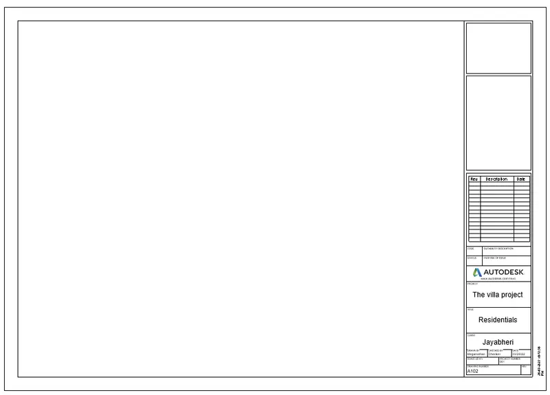
- For that the sheet template should be created as per the building details, and the building details can be filled in the Project Information option from the Manage tab.
- The Sheet will be then created from VIEW TAB< SHEET < NEW SHEET or LOAD SHEET .
- After creating a template, the template will be fillled with the Required Informations of the building from the Project information.
RESULT :
- Here in the result we can see the sheet template was created as per the filled Project Information .
6. Using the elevation tab create the elevation views, looking at your building from East, North, South, and West :
AIM :
To Create a elevation views of East, North, South, and West by looking at the building created .
INTRODUCTION :
- In Revit, we can create the 2D layout and 3D model of the building.
- Here, we can add the architectural elements such as FLOORS, WALLS, DOORS, WINDOWS and other architectural elements with desired colors, types and dimensions.
- We can also convert the 2D layout to the 3D Model by changing it into the Default 3D view.
- Like we discussed before, we can make LEVEL LINES such as Ground floor level, First floor level etc and the GRID LINES for the building models.
- We can also make the created 3D model into the various visual styles as desired, the visual styles such as 2D wireframe, shaded, conceptual, Realistic etc.
- The view cube plays the major in the 3D modelling of the buildings, because it helps to see the created model in all the 360 degree angles.
- In revit we can see the rooms created inside the 3D model from the paricular hight and angle with the help of CAMERA tool in the view tool bar.
- The main TWO TABS which are used to CREATE and EDIT the 3D models are "Project browser" and "Properties" .
PROCEDURE:
- First the LEVELS of the building should be created from "Ground level" to the "roof level" before starting of the building layout.
- Before start creating the layout of the building, the Units of the project should be set as per the project requirements.
- The setting of the units are done by selecting MANAGE TAB < PROJECT UNITS and by selecting appropriate units as required.
- Then the layout should be start to create from the Ground level by creating the FLOOR of 4" with the floor creating tool of the dimension of 40' x 60'.
- Followed by the walls are created above the floor , by selecting ARCHITECTURE TAB< WALL and mentioning the wall height as 10' and wall offset as 9" for exterior wall.
- After creating the Exterior wall, the Interior walls (partition walls) are needs to be created with the offset values of 4.5" as desired sizes of rooms needed inside the bluiding.
- Then the AREAS of the rooms should be tagged with the help of the ROOM TAG tool from the ARCHITECTURE TAB < ROOM or AREA.
- By picking the area inside the room, the area of the room will be tagged along with inner area and the name or details of the ROOMS can be edited as desired .
- Then the Doors and Windows are then allowed to add in the walls upto a certain height such as the WINDOWS are need to be placed over the sill level means at the height of 3' from the floor level.
- Likwise the DOORS are needs to be placed over floor level to the lintel level means upto 7', the height and the width of the doors varies depend upon the requirement of the places.
- The MAIN DOOR placed in the entrance are 4' x 7', DOORS used for the rooms are 3' x 7' and the Doors used for the Rest rooms are 2'6" x 7'.
- Likewise the WINDOWS height and widths are varies as desired, these DOORS and WINDOWS are selected and placed in wall by clicking the walls.
- The "Doors" are added to the created layout, by selecting the "ARCHITECTURE TAB" in the tool bar and select Door < Load family < US < Door (family).
- Likewise the "Windows" are added to the created layout, by select the "ARCHITECTURE TAB" in the tool bar and select Windows < Load family < US < Window (family).
- After loading the required DOORS and WINDOWS, it is inserted inside the file from ARCHITECTURE TAB < COMPONENT < PLACE COMPONENT.
- Followed by the DOORS and WINDOWS, the " Furnitures " are need to be loaded and placed at the required place.
- The "Furnitures" are added into the created layout, by selecting the "ARCHITECTURE TAB" in the tool bar and select Component < Load family < US < Furnitures (family).
- Then the PLUMBING FIXTURES and the WATER CLOSETS are addded at the desired places such as REST ROOMS and KITCHEN or as required.
- Likewise the all ELEMENTS are placed or added inside the building model from the COMPONENT TOOL from the ARCHITECTURE TAB and placing it in the desired places.
- Then the Created Ground floor will be copied and pasted over the First floor, after coping the Ground floor model PASTE < PLACE AT THE LEVEL SELECTED.
- Before start pasting, make sure that the First floor level line should be selected.
- Followed by, the Roof of the First floor model should be created by changing the 3D model to the 2D layout and clicking the Roof plan view from the PROJECT BROWSER, then the roof will be created over the exterior walls.
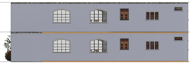
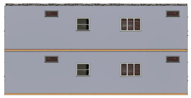
- Then the Elevations of all the directions should be created from PROPERTIES BROWSER < ELEVATION < EAST or NORTH or SOUTH or WEST.
RESULT :
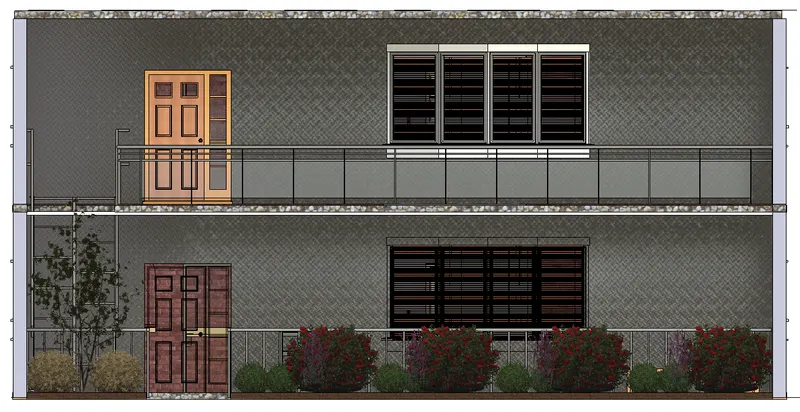
- Here in the result we can see the different types of ELEVATIONS are created such as EASE, NORTH, SOUTH, WEST.
- Also can see the different architectural compnents are created in the Elevation below.
- The architectural elements such as WALLS, DOORS and WINDOWS are attached in the created layout.
- The various types of elements have been attached from different families and categories with desired dimensions as required.
- The created Ground floor with walls are copied and pasted at the First floor level along with its components.
- The thickness of the Exterior walls are 9" and the Interior walls are 4.5".
- The area of the total 3D model of this residential building created was 40' x 60'.
- The thickness of the Floors and the Roof are 4".
EAST ELEVATION VIEW
NORTH ELEVATION VIEW
SOUTH ELEVATION VIEW
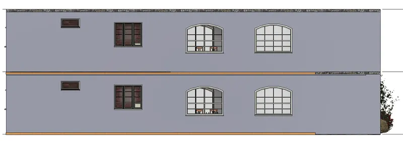
WEST ELEVATION VIEW
7. Produce section cut through each room either cutting across longitudinally or in a transverse direction :
AIM :
To Create a sectional view by the section cut through each room either cutting across longitudinally or in a transverse direction.
INTRODUCTION :
- In Revit, we can create the 2D layout and 3D model of the building.
- Here, we can add the architectural elements such as FLOORS, WALLS, DOORS, WINDOWS and other architectural elements with desired colors, types and dimensions.
- We can also convert the 2D layout to the 3D Model by changing it into the Default 3D view.
- Like we discussed before, we can make LEVEL LINES such as Ground floor level, First floor level etc and the GRID LINES for the building models.
- We can also make the created 3D model into the various visual styles as desired, the visual styles such as 2D wireframe, shaded, conceptual, Realistic etc.
- The view cube plays the major in the 3D modelling of the buildings, because it helps to see the created model in all the 360 degree angles.
- In revit we can see the rooms created inside the 3D model from the paricular hight and angle with the help of CAMERA tool in the view tool bar.
- The main TWO TABS which are used to CREATE and EDIT the 3D models are "Project browser" and "Properties" .
PROCEDURE:
- First the LEVELS of the building should be created from "Ground level" to the "roof level" before starting of the building layout.
- Before start creating the layout of the building, the Units of the project should be set as per the project requirements.
- The setting of the units are done by selecting MANAGE TAB < PROJECT UNITS and by selecting appropriate units as required.
- Then the layout should be start to create from the Ground level by creating the FLOOR of 4" with the floor creating tool of the dimension of 40' x 60'.
- Followed by the walls are created above the floor , by selecting ARCHITECTURE TAB< WALL and mentioning the wall height as 10' and wall offset as 9" for exterior wall.
- After creating the Exterior wall, the Interior walls (partition walls) are needs to be created with the offset values of 4.5" as desired sizes of rooms needed inside the bluiding.
- Then the AREAS of the rooms should be tagged with the help of the ROOM TAG tool from the ARCHITECTURE TAB < ROOM or AREA.
- By picking the area inside the room, the area of the room will be tagged along with inner area and the name or details of the ROOMS can be edited as desired .
- Then the Doors and Windows are then allowed to add in the walls upto a certain height such as the WINDOWS are need to be placed over the sill level means at the height of 3' from the floor level.
- Likwise the DOORS are needs to be placed over floor level to the lintel level means upto 7', the height and the width of the doors varies depend upon the requirement of the places.
- The MAIN DOOR placed in the entrance are 4' x 7', DOORS used for the rooms are 3' x 7' and the Doors used for the Rest rooms are 2'6" x 7'.
- Likewise the WINDOWS height and widths are varies as desired, these DOORS and WINDOWS are selected and placed in wall by clicking the walls.
- The "Doors" are added to the created layout, by selecting the "ARCHITECTURE TAB" in the tool bar and select Door < Load family < US < Door (family).
- Likewise the "Windows" are added to the created layout, by select the "ARCHITECTURE TAB" in the tool bar and select Windows < Load family < US < Window (family).
- After loading the required DOORS and WINDOWS, it is inserted inside the file from ARCHITECTURE TAB < COMPONENT < PLACE COMPONENT.
- Followed by the DOORS and WINDOWS, the " Furnitures " are need to be loaded and placed at the required place.
- The "Furnitures" are added into the created layout, by selecting the "ARCHITECTURE TAB" in the tool bar and select Component < Load family < US < Furnitures (family).
- Then the PLUMBING FIXTURES and the WATER CLOSETS are addded at the desired places such as REST ROOMS and KITCHEN or as required.
- Likewise the all ELEMENTS are placed or added inside the building model from the COMPONENT TOOL from the ARCHITECTURE TAB and placing it in the desired places.
- Then the Created Ground floor will be copied and pasted over the First floor, after coping the Ground floor model PASTE < PLACE AT THE LEVEL SELECTED.
- Before start pasting, make sure that the First floor level line should be selected.
- Followed by, the Roof of the First floor model should be created by changing the 3D model to the 2D layout and clicking the Roof plan view from the PROJECT BROWSER, then the roof will be created over the exterior walls.
- Then from the created building model, the SECTIONAL VIEW should be created by cutting through either in the longitudinal or Transverse direction.
- The Section tool will be evoked form VIEW TAB < SECTION and start creating the longitudinal or Transverse line by cutting the Rooms, the Sectional views will be created.
RESULT :
- Here in the result we can see the Sectional views are created for all the rooms of the building.
- We can also see all the different types of architectural components are created inside the building model.
- The architectural elements such as WALLS, DOORS and WINDOWS are attached in the created layout.
- The various types of elements have been attached from different families and categories with desired dimensions as required.
- The created Ground floor with walls are copied and pasted at the First floor level along with its components.
- The thickness of the Exterior walls are 9" and the Interior walls are 4.5".
- The area of the total 3D model of this residential building created was 40' x 60'.
- The thickness of the Floors and the Roof are 4".
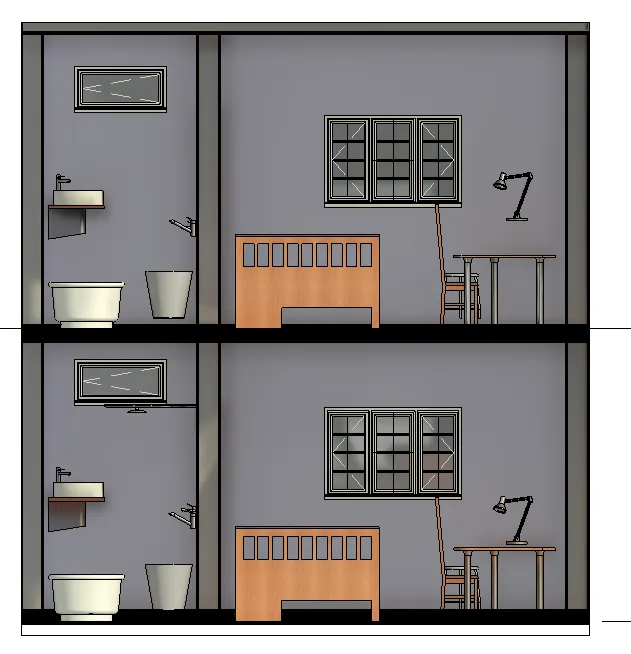
SECTIONAL VIEW OF THE "BED ROOM 1"
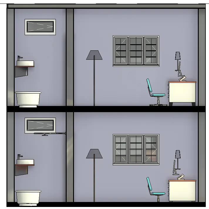
SECTIONAL VIEW OF THE "BED ROOM 2"
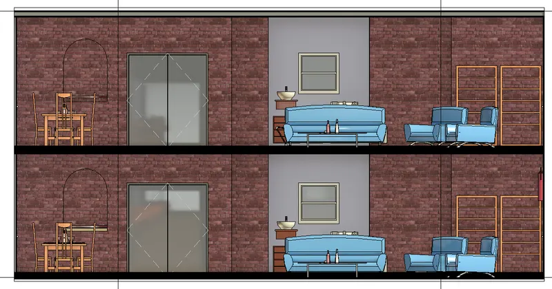
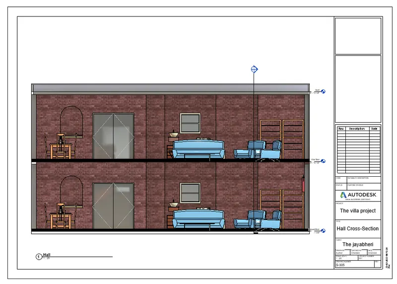
SECTIONAL VIEW OF THE "HALL/LIVING ROOM"
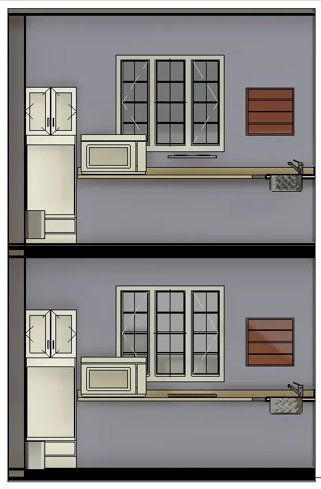
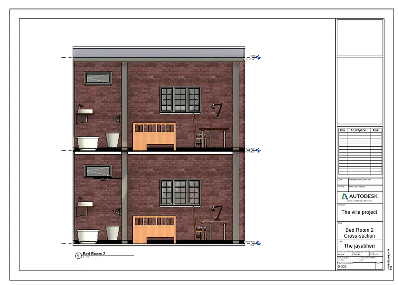
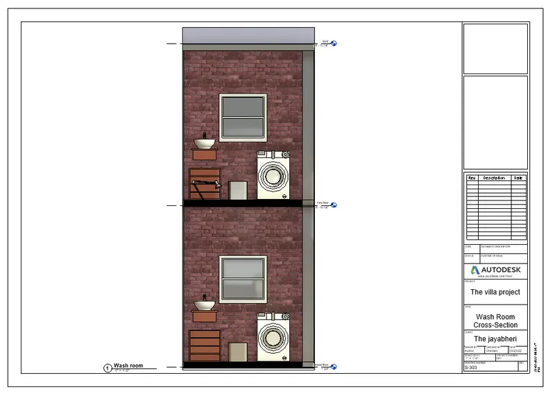
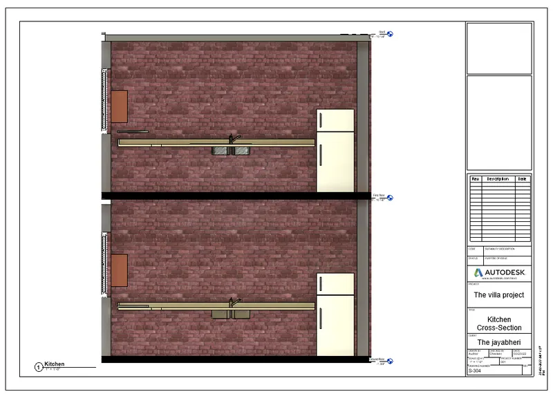
SECTIONAL VIEW OF "KITCHEN"
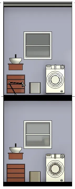
SECTIONAL VIEW OF THE "WASH ROOM"
8. Classify the views, Plan Views, Section Views, and Elevation views to Documentation category using Properties browser :
AIM :
To classify the views, Plan Views, Section Views, and Elevation views to either Design or Documentation category using Properties browser.
INTRODUCTION :
- In Revit, we can create the 2D layout and 3D model of the building.
- Here, we can add the architectural elements such as FLOORS, WALLS, DOORS, WINDOWS and other architectural elements with desired colors, types and dimensions.
- We can also convert the 2D layout to the 3D Model by changing it into the Default 3D view.
- Like we discussed before, we can make LEVEL LINES such as Ground floor level, First floor level etc and the GRID LINES for the building models.
- We can also make the created 3D model into the various visual styles as desired, the visual styles such as 2D wireframe, shaded, conceptual, Realistic etc.
- The view cube plays the major in the 3D modelling of the buildings, because it helps to see the created model in all the 360 degree angles.
- In revit we can see the rooms created inside the 3D model from the paricular hight and angle with the help of CAMERA tool in the view tool bar.
- The main TWO TABS which are used to CREATE and EDIT the 3D models are "Project browser" and "Properties" .
PROCEDURE:
- First the LEVELS of the building should be created from "Ground level" to the "roof level" before starting of the building layout.
- Before start creating the layout of the building, the Units of the project should be set as per the project requirements.
- The setting of the units are done by selecting MANAGE TAB < PROJECT UNITS and by selecting appropriate units as required.
- Then the layout should be start to create from the Ground level by creating the FLOOR of 4" with the floor creating tool of the dimension of 40' x 60'.
- Followed by the walls are created above the floor , by selecting ARCHITECTURE TAB< WALL and mentioning the wall height as 10' and wall offset as 9" for exterior wall.
- After creating the Exterior wall, the Interior walls (partition walls) are needs to be created with the offset values of 4.5" as desired sizes of rooms needed inside the bluiding.
- Then the AREAS of the rooms should be tagged with the help of the ROOM TAG tool from the ARCHITECTURE TAB < ROOM or AREA.
- By picking the area inside the room, the area of the room will be tagged along with inner area and the name or details of the ROOMS can be edited as desired .
- Then the Doors and Windows are then allowed to add in the walls upto a certain height such as the WINDOWS are need to be placed over the sill level means at the height of 3' from the floor level.
- Likwise the DOORS are needs to be placed over floor level to the lintel level means upto 7', the height and the width of the doors varies depend upon the requirement of the places.
- The MAIN DOOR placed in the entrance are 4' x 7', DOORS used for the rooms are 3' x 7' and the Doors used for the Rest rooms are 2'6" x 7'.
- Likewise the WINDOWS height and widths are varies as desired, these DOORS and WINDOWS are selected and placed in wall by clicking the walls.
- The "Doors" are added to the created layout, by selecting the "ARCHITECTURE TAB" in the tool bar and select Door < Load family < US < Door (family).
- Likewise the "Windows" are added to the created layout, by select the "ARCHITECTURE TAB" in the tool bar and select Windows < Load family < US < Window (family).
- After loading the required DOORS and WINDOWS, it is inserted inside the file from ARCHITECTURE TAB < COMPONENT < PLACE COMPONENT.
- Followed by the DOORS and WINDOWS, the " Furnitures " are need to be loaded and placed at the required place.
- The "Furnitures" are added into the created layout, by selecting the "ARCHITECTURE TAB" in the tool bar and select Component < Load family < US < Furnitures (family).
- Then the PLUMBING FIXTURES and the WATER CLOSETS are addded at the desired places such as REST ROOMS and KITCHEN or as required.
- Likewise the all ELEMENTS are placed or added inside the building model from the COMPONENT TOOL from the ARCHITECTURE TAB and placing it in the desired places.
- Then the Created Ground floor will be copied and pasted over the First floor, after coping the Ground floor model PASTE < PLACE AT THE LEVEL SELECTED.
- Before start pasting, make sure that the First floor level line should be selected.
- Followed by, the Roof of the First floor model should be created by changing the 3D model to the 2D layout and clicking the Roof plan view from the PROJECT BROWSER, then the roof will be created over the exterior walls.
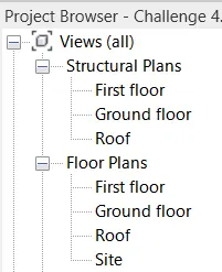
- Then we can classify all the views of the BuilidIng model and edit it from the PROJECT BROWSER .
- The Floor plans can be viewed as PROJECT BROWSER < FLOOR PLANS < GROUND FLOOR (or) FIRST FLOOR (or) ROOF.
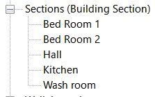
- The Sectional plans can be viewed as PROJECT BROWSER < SECTIONS < BED ROOM 1 (or) BED ROOM 2 (or) HALL (or) KITCHEN (or) WASH ROOM .
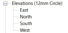
- The Elevation plans can be viewed as PROJECT BROWSER < ELEVATIONS < EAST (or) NORTH (or) SOUTH (or) WEST .
RESULT :
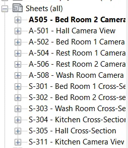
- Here in the result we can see the different Classifiactions of the views of the building model.
9. Using the sheet template produced create multiple sheets :
AIM :
To Create a multiple sheets by using the sheet template produced from the view tab.
INTRODUCTION :
- In Revit, we can create the 2D layout and 3D model of the building.
- Here, we can add the architectural elements such as FLOORS, WALLS, DOORS, WINDOWS and other architectural elements with desired colors, types and dimensions.
- We can also convert the 2D layout to the 3D Model by changing it into the Default 3D view.
- Like we discussed before, we can make LEVEL LINES such as Ground floor level, First floor level etc and the GRID LINES for the building models.
- We can also make the created 3D model into the various visual styles as desired, the visual styles such as 2D wireframe, shaded, conceptual, Realistic etc.
- The view cube plays the major in the 3D modelling of the buildings, because it helps to see the created model in all the 360 degree angles.
- In revit we can see the rooms created inside the 3D model from the paricular hight and angle with the help of CAMERA tool in the view tool bar.
- The main TWO TABS which are used to CREATE and EDIT the 3D models are "Project browser" and "Properties" .
PROCEDURE:
- First the LEVELS of the building should be created from "Ground level" to the "roof level" before starting of the building layout.
- Before start creating the layout of the building, the Units of the project should be set as per the project requirements.
- The setting of the units are done by selecting MANAGE TAB < PROJECT UNITS and by selecting appropriate units as required.
- Then the layout should be start to create from the Ground level by creating the FLOOR of 4" with the floor creating tool of the dimension of 40' x 60'.
- Followed by the walls are created above the floor , by selecting ARCHITECTURE TAB< WALL and mentioning the wall height as 10' and wall offset as 9" for exterior wall.
- After creating the Exterior wall, the Interior walls (partition walls) are needs to be created with the offset values of 4.5" as desired sizes of rooms needed inside the bluiding.
- Then the AREAS of the rooms should be tagged with the help of the ROOM TAG tool from the ARCHITECTURE TAB < ROOM or AREA.
- By picking the area inside the room, the area of the room will be tagged along with inner area and the name or details of the ROOMS can be edited as desired .
- Then the Doors and Windows are then allowed to add in the walls upto a certain height such as the WINDOWS are need to be placed over the sill level means at the height of 3' from the floor level.
- Likwise the DOORS are needs to be placed over floor level to the lintel level means upto 7', the height and the width of the doors varies depend upon the requirement of the places.
- The MAIN DOOR placed in the entrance are 4' x 7', DOORS used for the rooms are 3' x 7' and the Doors used for the Rest rooms are 2'6" x 7'.
- Likewise the WINDOWS height and widths are varies as desired, these DOORS and WINDOWS are selected and placed in wall by clicking the walls.
- The "Doors" are added to the created layout, by selecting the "ARCHITECTURE TAB" in the tool bar and select Door < Load family < US < Door (family).
- Likewise the "Windows" are added to the created layout, by select the "ARCHITECTURE TAB" in the tool bar and select Windows < Load family < US < Window (family).
- After loading the required DOORS and WINDOWS, it is inserted inside the file from ARCHITECTURE TAB < COMPONENT < PLACE COMPONENT.
- Followed by the DOORS and WINDOWS, the " Furnitures " are need to be loaded and placed at the required place.
- The "Furnitures" are added into the created layout, by selecting the "ARCHITECTURE TAB" in the tool bar and select Component < Load family < US < Furnitures (family).
- Then the PLUMBING FIXTURES and the WATER CLOSETS are addded at the desired places such as REST ROOMS and KITCHEN or as required.
- Likewise the all ELEMENTS are placed or added inside the building model from the COMPONENT TOOL from the ARCHITECTURE TAB and placing it in the desired places.
- Then the Created Ground floor will be copied and pasted over the First floor, after coping the Ground floor model PASTE < PLACE AT THE LEVEL SELECTED.
- Before start pasting, make sure that the First floor level line should be selected.
- Followed by, the Roof of the First floor model should be created by changing the 3D model to the 2D layout and clicking the Roof plan view from the PROJECT BROWSER, then the roof will be created over the exterior walls.
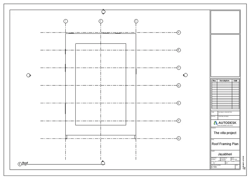
- After the completion of the Building model creation, the created plan should be inserted into the sheet.
- For that the sheet template should be created as per the building details, and the building details can be filled in the Project Information option from the Manage tab.
- The Sheet will be then created from VIEW TAB< SHEET < NEW SHEET or LOAD SHEET .
- After creating a template, the template will be fillled with the Required Informations of the building from the Project information.
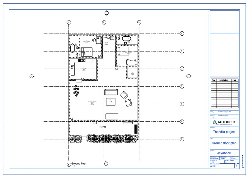
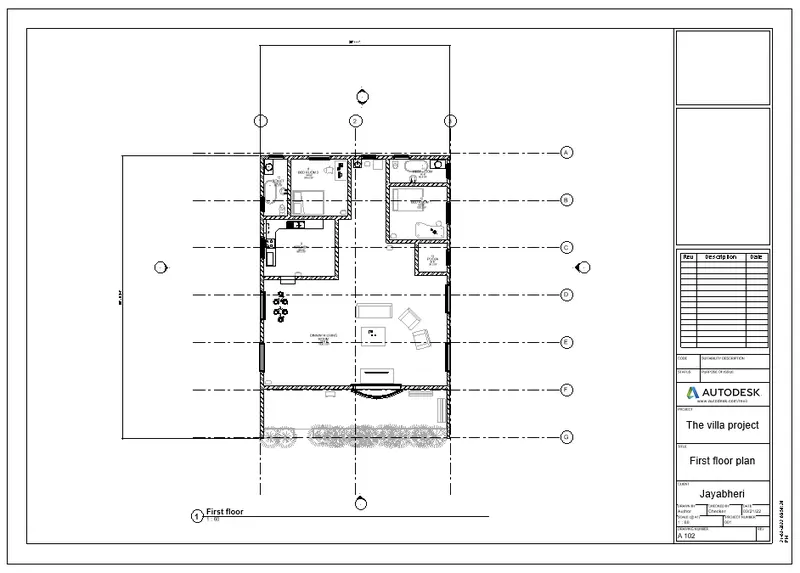
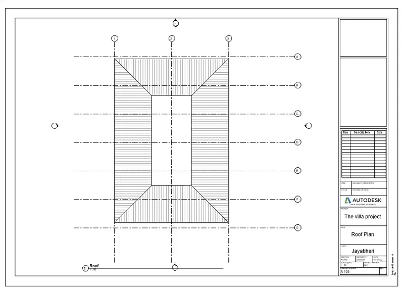
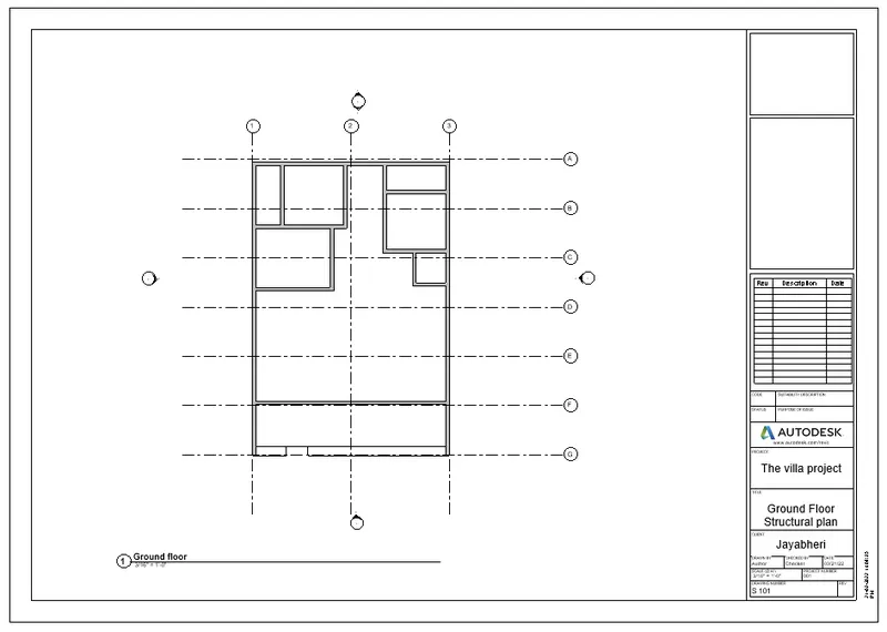
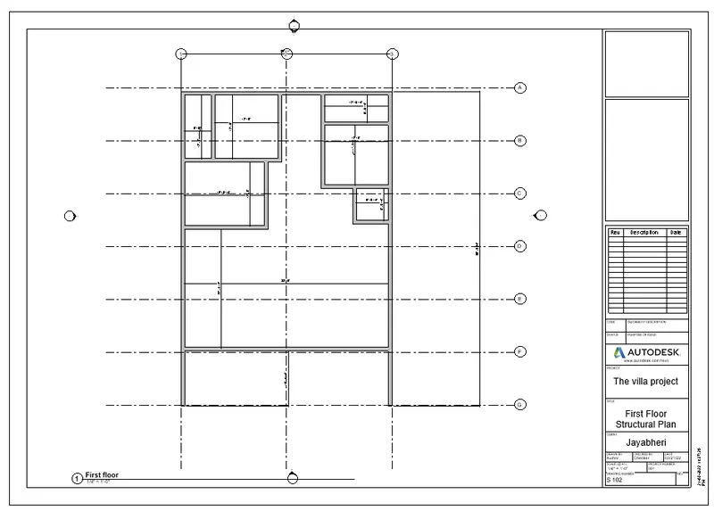
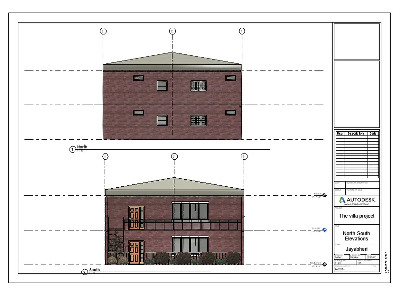
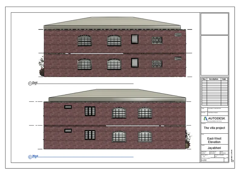
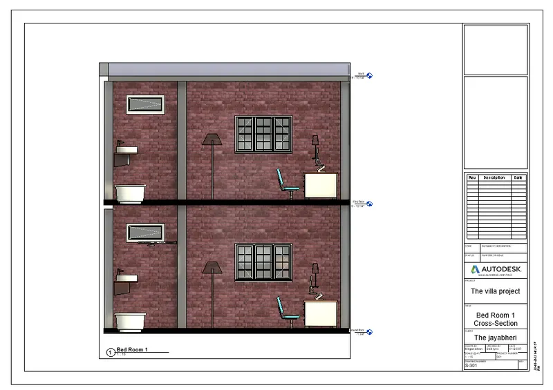
- Then the created 3D models should be dragged into the created sheet template as per the required building view.
- Those sheets are then named as per required such as A-101, S-101, A-201 etc.
RESULT :
- Here in the result we can see the different sheet templates are created and the required building views are added into it.
- The architectural elements such as WALLS, DOORS and WINDOWS are attached in the created layout.
- The various types of elements have been attached from different families and categories with desired dimensions as required.
- The created Ground floor with walls are copied and pasted at the First floor level along with its components.
- The thickness of the Exterior walls are 9" and the Interior walls are 4.5".
- The area of the total 3D model of this residential building created was 40' x 60'.
- The thickness of the Floors and the Roof are 4".
10. Create a camera-specific view or a 3D view in each rooms and based on the views create a new set of sheets starting A-501 and add as many sheets after, 502, 503.. n to place the 3D view images :
AIM :
To Create a camera-specific view or a 3D view in each room ( living, dining, bedroom) and based on the views create a new set of sheets starting A-501 and add as many sheets after, 502, 503.. n to place the 3D view images.
INTRODUCTION :
- In Revit, we can create the 2D layout and 3D model of the building.
- Here, we can add the architectural elements such as FLOORS, WALLS, DOORS, WINDOWS and other architectural elements with desired colors, types and dimensions.
- We can also convert the 2D layout to the 3D Model by changing it into the Default 3D view.
- Like we discussed before, we can make LEVEL LINES such as Ground floor level, First floor level etc and the GRID LINES for the building models.
- We can also make the created 3D model into the various visual styles as desired, the visual styles such as 2D wireframe, shaded, conceptual, Realistic etc.
- The view cube plays the major in the 3D modelling of the buildings, because it helps to see the created model in all the 360 degree angles.
- In revit we can see the rooms created inside the 3D model from the paricular hight and angle with the help of CAMERA tool in the view tool bar.
- The main TWO TABS which are used to CREATE and EDIT the 3D models are "Project browser" and "Properties" .
PROCEDURE:
- First the LEVELS of the building should be created from "Ground level" to the "roof level" before starting of the building layout.
- Before start creating the layout of the building, the Units of the project should be set as per the project requirements.
- The setting of the units are done by selecting MANAGE TAB < PROJECT UNITS and by selecting appropriate units as required.
- Then the layout should be start to create from the Ground level by creating the FLOOR of 4" with the floor creating tool of the dimension of 40' x 60'.
- Followed by the walls are created above the floor , by selecting ARCHITECTURE TAB< WALL and mentioning the wall height as 10' and wall offset as 9" for exterior wall.
- After creating the Exterior wall, the Interior walls (partition walls) are needs to be created with the offset values of 4.5" as desired sizes of rooms needed inside the bluiding.
- Then the AREAS of the rooms should be tagged with the help of the ROOM TAG tool from the ARCHITECTURE TAB < ROOM or AREA.
- By picking the area inside the room, the area of the room will be tagged along with inner area and the name or details of the ROOMS can be edited as desired .
- Then the Doors and Windows are then allowed to add in the walls upto a certain height such as the WINDOWS are need to be placed over the sill level means at the height of 3' from the floor level.
- Likwise the DOORS are needs to be placed over floor level to the lintel level means upto 7', the height and the width of the doors varies depend upon the requirement of the places.
- The MAIN DOOR placed in the entrance are 4' x 7', DOORS used for the rooms are 3' x 7' and the Doors used for the Rest rooms are 2'6" x 7'.
- Likewise the WINDOWS height and widths are varies as desired, these DOORS and WINDOWS are selected and placed in wall by clicking the walls.
- The "Doors" are added to the created layout, by selecting the "ARCHITECTURE TAB" in the tool bar and select Door < Load family < US < Door (family).
- Likewise the "Windows" are added to the created layout, by select the "ARCHITECTURE TAB" in the tool bar and select Windows < Load family < US < Window (family).
- After loading the required DOORS and WINDOWS, it is inserted inside the file from ARCHITECTURE TAB < COMPONENT < PLACE COMPONENT.
- Followed by the DOORS and WINDOWS, the " Furnitures " are need to be loaded and placed at the required place.
- The "Furnitures" are added into the created layout, by selecting the "ARCHITECTURE TAB" in the tool bar and select Component < Load family < US < Furnitures (family).
- Then the PLUMBING FIXTURES and the WATER CLOSETS are addded at the desired places such as REST ROOMS and KITCHEN or as required.
- Likewise the all ELEMENTS are placed or added inside the building model from the COMPONENT TOOL from the ARCHITECTURE TAB and placing it in the desired places.
- Then the Created Ground floor will be copied and pasted over the First floor, after coping the Ground floor model PASTE < PLACE AT THE LEVEL SELECTED.
- Before start pasting, make sure that the First floor level line should be selected.
- Followed by, the Roof of the First floor model should be created by changing the 3D model to the 2D layout and clicking the Roof plan view from the PROJECT BROWSER, then the roof will be created over the exterior walls.
- We can view the interiors of the building by fixing the CAMERA inside the 3D model and saving the view as desired name and view whenever required.
- It is done by VIEW TAB < 3D VIEW < CAMERA .
- After the completion of the Building model creation, the created plan should be inserted into the sheet.
- For that the sheet template should be created as per the building details, and the building details can be filled in the Project Information option from the Manage tab.
- The Sheet will be then created from VIEW TAB< SHEET < NEW SHEET or LOAD SHEET .
- After creating a template, the template will be fillled with the Required Informations of the building from the Project information.
- Then we should create a camera-specific view or a 3D view in each room from VIEW TAB< CAMERA .
- And then Place the camera in the desired position to see the view as required.
- Based on the views create a new set of sheets starting A-501 and we can add as many sheets after, 502, 503.. n to place the 3D view images.
- Then the created Camera view should be dragged into the created sheet template as per the required building view.
RESULT :
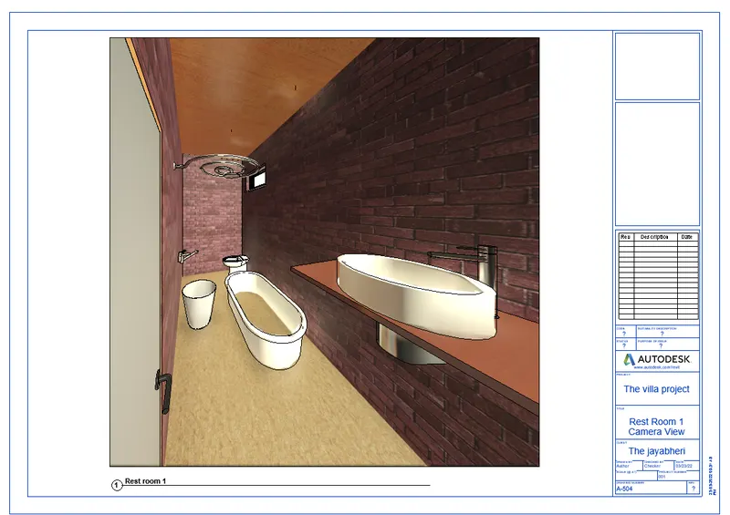
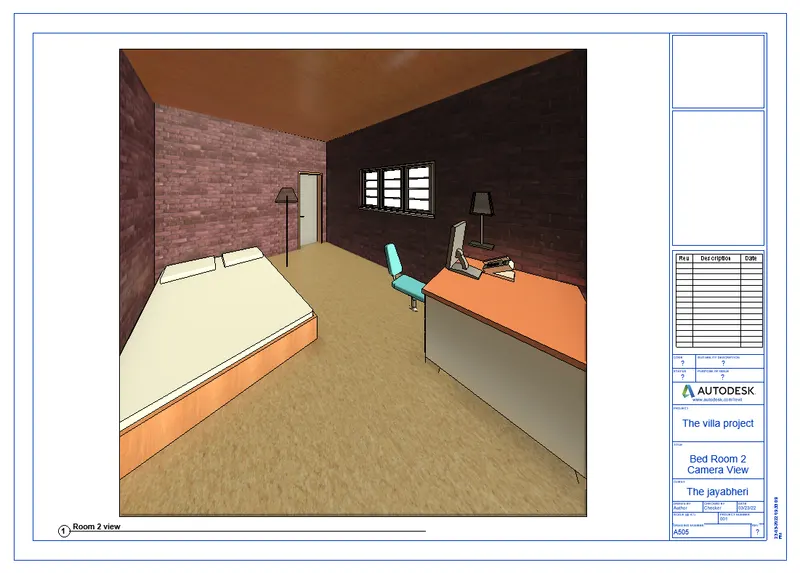
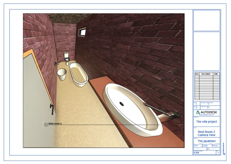
- Here in the result we can see the different camera views created by the camera tool from the View Tab.
- Also we can see the different types of architectural components are created in the building model.
- The architectural elements such as WALLS, DOORS and WINDOWS are attached in the created layout.
- The various types of elements have been attached from different families and categories with desired dimensions as required.
- The created Ground floor with walls are copied and pasted at the First floor level along with its components.
- The thickness of the Exterior walls are 9" and the Interior walls are 4.5".
- The area of the total 3D model of this residential building created was 40' x 60'.
- The thickness of the Floors and the Roof are 4".