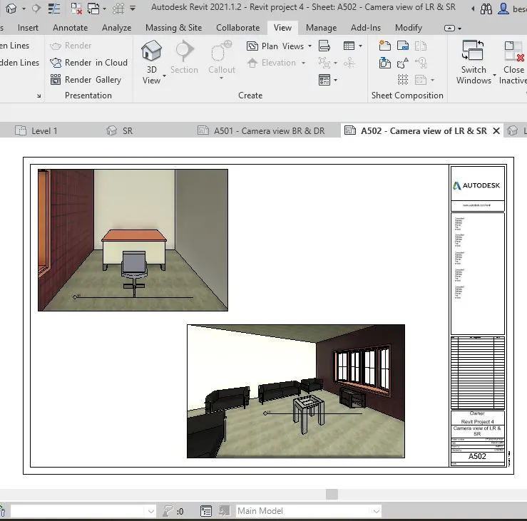
3D Creation of Ceiling, Roof, Architectural plan, Structural plan, Sectional view, Elevation view and Camera specific view for a house plan using REVIT
QUESTIONS
1) Based on the project saved from Week 3, proceed from the First Floor Level. Model a Ceiling from the architecture tab above the walls at the first-floor level
2) Model a roof above the ceiling by selecting the footprints of the ceiling. Using the adjustment toolbars appearing on-screen adjust the roof slope to 10 degrees
3) Using the file saved from weeks 2 to 4, create plan views for ground floor level and first-floor level including all the walls, floors, and components. Separate them to
architecture and structural plans
a. Architecture plan must have walls, floors, and all the components placed within the building
b. Structure plan must have details of only walls, floors, and columns
4) Using annotate toolbar add dimensions to all the walls and floors with reference to the longitudinal and transverse grids created in the project file
a. The architecture plan dimensions include details on where the components are placed within the buildings with relation to grids. Overall dimensions are sufficient for architecture plans
b. The Structure plan dimensions must include details on the position of all the walls and interior walls with reference to grids. Locate all the framing components of the building with reference to a fixed point using Structural plans
5) Create a sheet template from the view tab and adjust the parameters on the sheet to add appropriate views
6) Using the elevation tab create the elevation views, looking at your building from East, North, South, and West
7) Produce section cut through each room either cutting across longitudinally or in a transverse direction
8) Classify the views, Plan Views, Section Views, and Elevation views to either Design or Documentation category using Properties browser
9) Using the sheet template produced create multiple sheets as follows
a. A 101- Ground Floor Architecture Plan
b. A 102- First Floor Architecture Plan
c. A 103- Roof Plan
d. S 101- Ground Floor Structural Plan
e. S 102- First Floor Structural Plan
f. S 103- Roof Framing Plan
g. A-201- North-South Elevations
h. A-202- East-West Elevations
Add additional sheets based on the sections created in your Revit file
10) Create a camera-specific view or a 3D view in each room ( living, dining, bedroom). Based on the views create a new set of sheets starting A-501 (you can add as many sheets after, 502, 503.. n)to place the 3D view images. Produce the sheets as a part of project drafting.
ANSWERS
1) Based on the project saved from Week 3, proceed from the First Floor Level. Model a Ceiling from the architecture tab above the walls at the first-floor level
AIM : To create model a Ceiling from the architecture tab above the walls at the first-floor level
INTRODUCTION :
Ceiling - Creates a ceiling at a specific distance above the level in which it resides
In Revit, the ceiling tool can be used to create ceilings in a reflected ceiling plan view. To access the tool, you can :
- Open a ceiling plan view
- Click the Architecture tab
- Click the Build panel
- Click Ceiling
PROCEDURE :
- Open Revit from the desktop
- Click on open tab
- Open Residential building 3 file
- Open a ceiling plan view
- Click the Architecture tab
- Click the Build panel
- Click Ceiling
- Click sketch ceiling
- Click pick lines
- Click on the wall boundaries & make it a closed loop
- Click finish edit mode
RESULT :
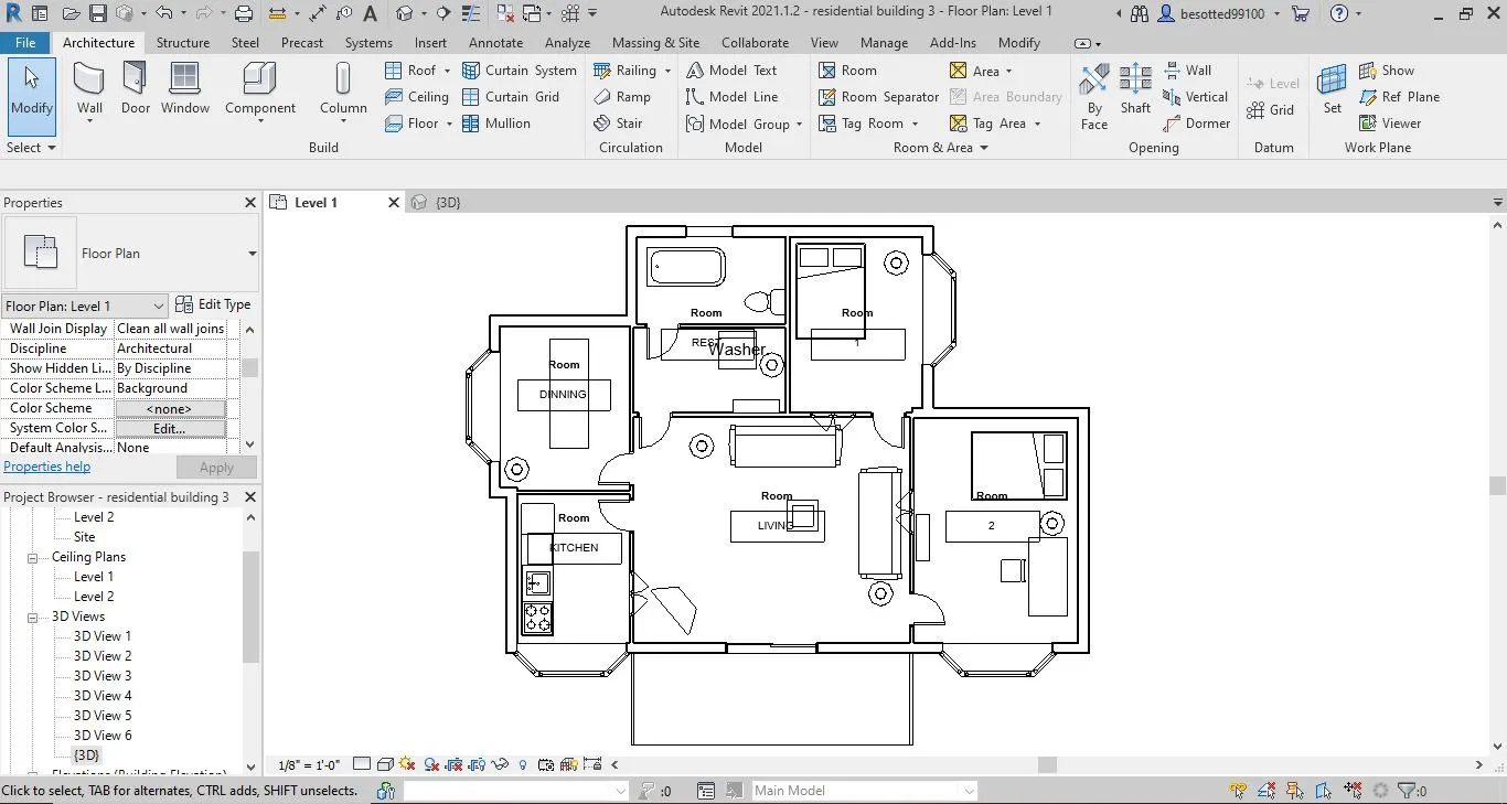
Plan view of Level 1
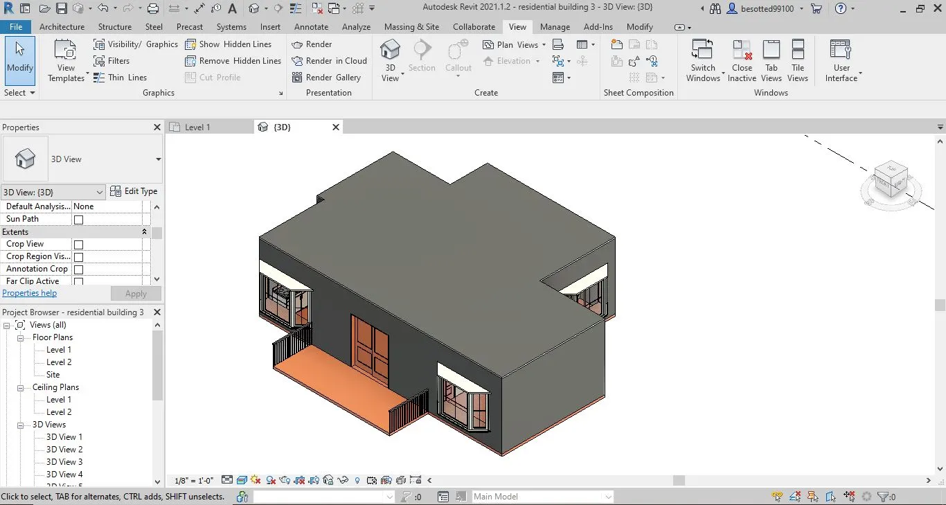
3D view with ceiling
2) Model a roof above the ceiling by selecting the footprints of the ceiling. Using the adjustment toolbars appearing on-screen adjust the roof slope to 10 degrees
AIM : To create a Model of roof above the ceiling by selecting the footprints of the ceiling
INTRODUCTION :
Roof - Create a roof using building footprint to define its boundaries.
Revit offers several methods of creating roofs. Choose the method that best meets the needs of your design.
You can create a roof -
A) from a building footprint
B) as an extrusion
C) with sloped glazing
D) from a mass instance
A roof cannot cut through windows or doors.
PROCEDURE :
- Open Revit from the desktop
- Click on open tab
- Open Residential building 3 file
- Open a Roof plan view
- Click the Architecture tab
- Click the Build panel
- Click Roof
- Select level 1 from lowest level dialogue
- Click pick lines
- Click on the Ceiling boundaries & make it a closed loop
- Click finish edit mode
RESULT :
3D view with ceiling
Slope 10 degree
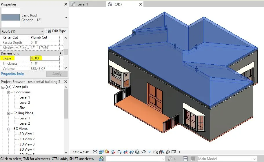
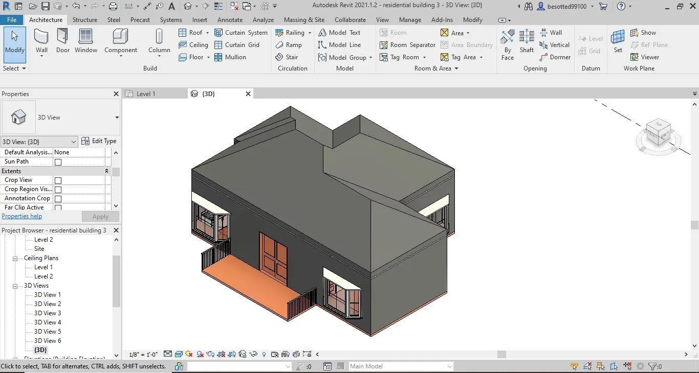
3D view with Roof
3) Using the file saved from weeks 2 to 4, create plan views for ground floor level and first-floor level including all the walls, floors, and components. Separate them to
architecture and structural plans
a. Architecture plan must have walls, floors, and all the components placed within the building
b. Structure plan must have details of only walls, floors, and columns
AIM : To create plan views for ground floor level and first-floor level including all the walls, floors, and components
& separate them to architecture and structural plans.
INTRODUCTION :
Plan view - A plan view gives you an entirely different perspective of the building you have designed. It's the view of the home or building from above and, usually, with the roof removed.
There are four types of plan views in Revit
- Floor plan
- Reflected ceiling plans
- structural floor plans
- Area plans
Architectural Plans - To put it simply, architectural plans are the overall design of a building. In addition to the design, they offer notes with detailed specifications regarding important components to the plan such as materials that will be used, area calculations, and more.
Structure Plans - Structural drawings, often referred to as "blueprints" or "plans," are detailed illustrations that depict the design and specification of a building's structural components. These drawings provide a comprehensive layout of how the structure will be constructed, from its foundation to its roof.
PROCEDURE :
- Open Revit from the desktop
- Click on open tab
- Select Revit project 4 file
- Click on view tool
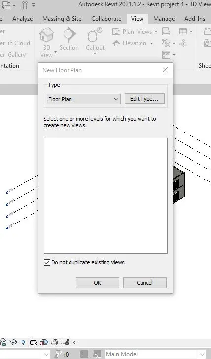
- Click on plan view
- Click on floor plan
- Click ok
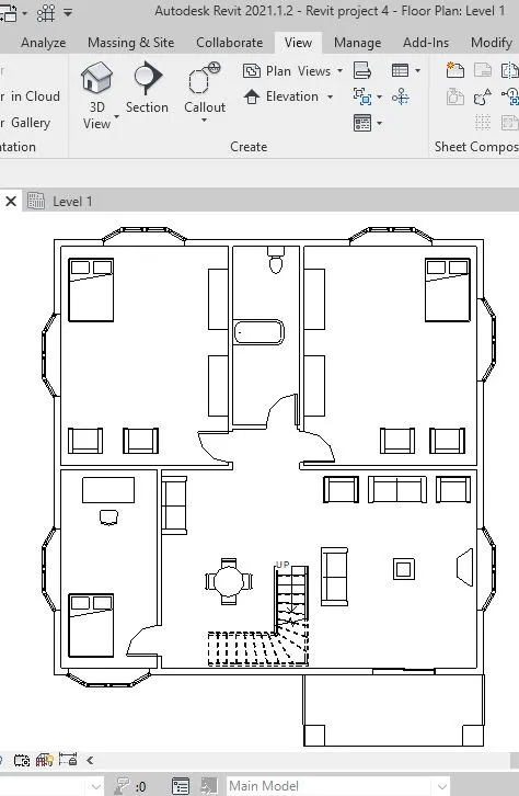
- Opened Floor plan level 1
- Click on view tool
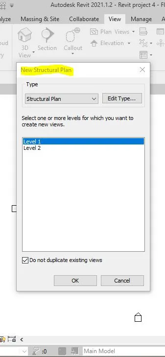
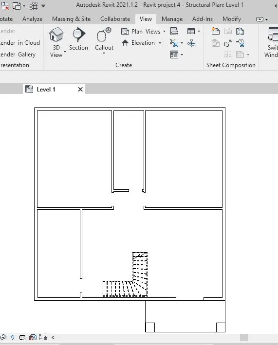
- Click on structure plan
- Select Level
- Click ok
- Opened Structure floor plan level 1
RESULT :
Opening Plan view

Opening Structural plan
Architectural Plans
Structure Plans
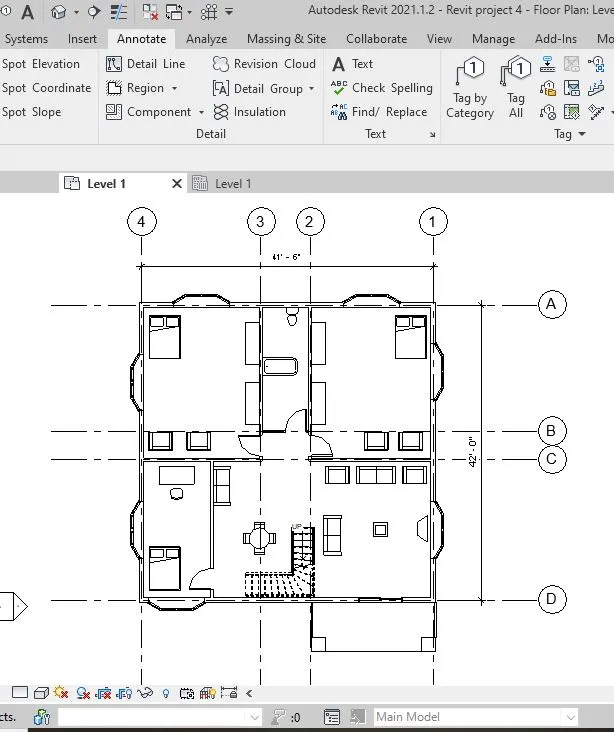
4) Using annotate toolbar add dimensions to all the walls and floors with reference to the longitudinal and transverse grids created in the project file
a. The architecture plan dimensions include details on where the components are placed within the buildings with relation to grids. Overall dimensions are sufficient for architecture plans
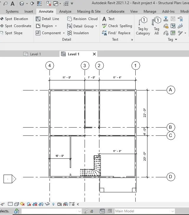
b. The Structure plan dimensions must include details on the position of all the walls and interior walls with reference to grids. Locate all the framing components of the building with reference to a fixed point using Structural plans
AIM : To add using annotate toolbar add dimensions to all the walls and floors with reference to the longitudinal and transverse grids created in the project file
INTRODUCTION :
Annotate toolbar - You can add additional information to your drawing by adding text notes. They are annotation elements which means that their size remains constant on the print and scales automatically with the scale of the drawing.
The annotate toolbar in Revit has several panels, including -
Dimensions, Details, Text, color, symbols
Levels/ Grids - Revit Levels and Grids are really the skeleton of building projects. Typically Levels in Revit are used to indicate the locations of floors, foundations, and the roof of a building in section and elevation views. More recent versions of Revit include Levels in 3D views. Grids are used to host columns and walls.
PROCEDURE :
- Open Revit from the desktop
- Click on open tab
- Select Revit project 4 file
- Click on Annotate tool
- Click on aligned dimension
- Click on Architecture tool
- Click on Grid
- Click on pick line
- Select on boundaries wall (external , internal)
- Rename the grids
RESULT :
Added dimensions annotate toolbar in Architecture plan view
Added dimensions annotate toolbar in Structure plan view
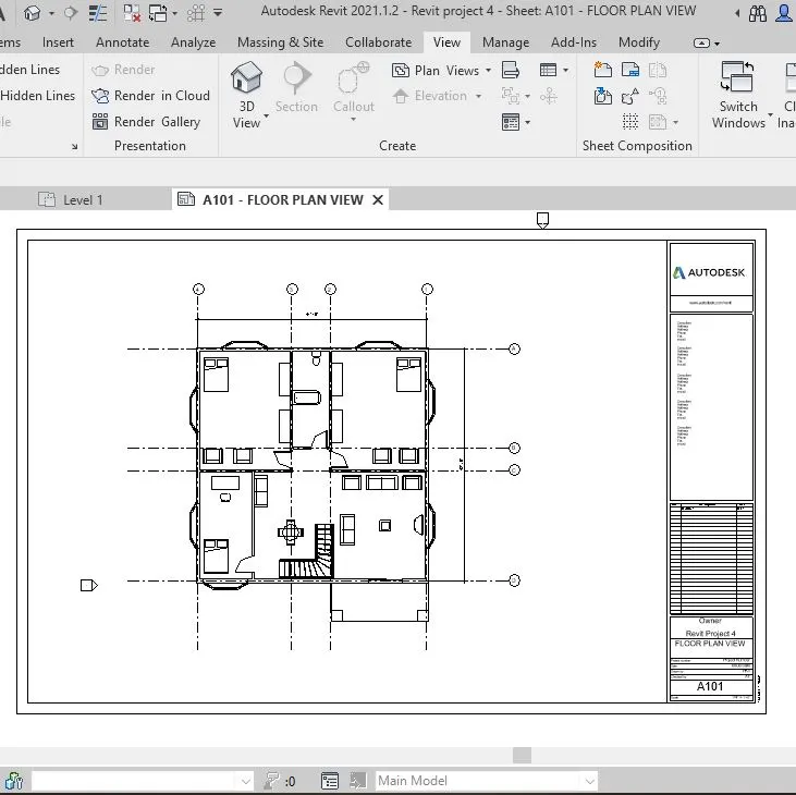
5) Create a sheet template from the view tab and adjust the parameters on the sheet to add appropriate views
AIM : To create a sheet template from the view tab and adjust the parameters on the sheet to add appropriate views
INTRODUCTION :
Sheet template - A sheet view in Revit is a layout where you can place-
- A Titleblock
- Multiple drawings (graphic views such as plan views, sections, elevation, details, 3D views)
- Multiple schedules
- Images
PROCEDURE :
- Open Revit from the desktop
- Click on open tab
- Select Revit project 4 file
- Click on View tool
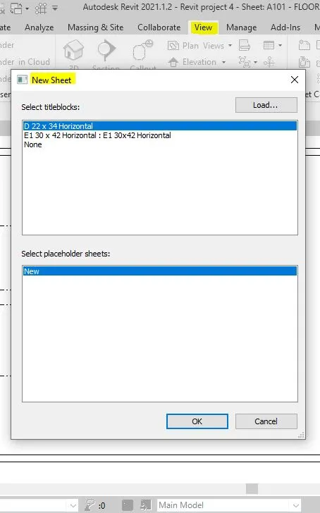
- Click sheet
- Select Titleblock D 22 X 34 Horizontal
- Click ok
- Change Sheet name
- Change Sheet No. - A101, A102....
- Change sheet issue date
- Change drawn by, checked by, designed by, approved by
- Drag elements into the sheet as per question
RESULT :
Created sheet
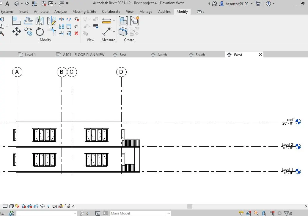
6) Using the elevation tab create the elevation views, looking at your building from East, North, South, and West
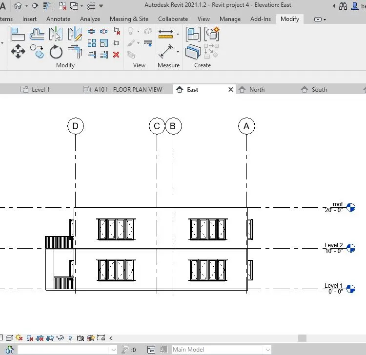
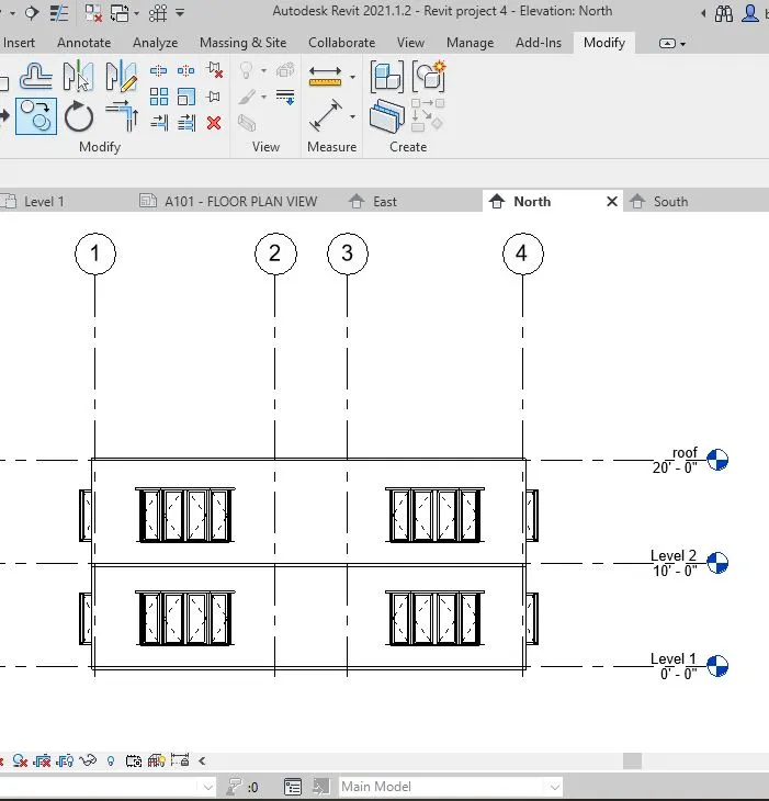
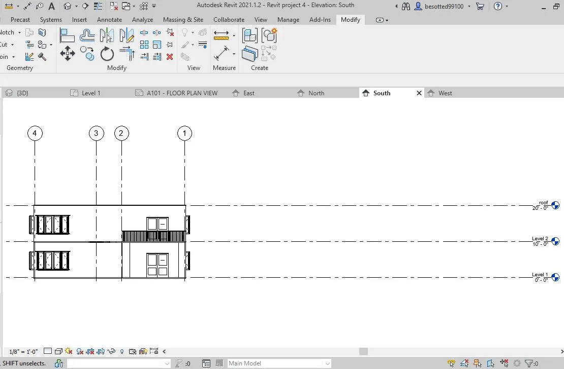
AIM : With the use the elevation tab create the elevation views, looking at your building from East, North, South, and West
INTRODUCTION :
Elevation tab - See a model's exterior or interior elevation perspectives from four default template directions or other directions that you specify. Elevation views are part of the default template in Revit.
PROCEDURE :
- Open Revit from the desktop
- Click on open tab
- Select Revit project 4 file
- Click on View tool
- Click on elevation
- In Revit elevation north, south, east, west is preinstalled
- Click on Architecture tool
- Click on Grid (GR)
RESULT :
Section view East
Section view North
Section view South
Section view West
7) Produce section cut through each room either cutting across longitudinally or in a transverse direction
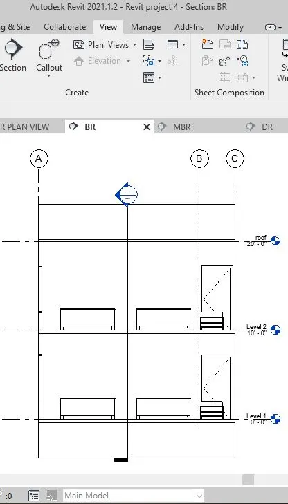
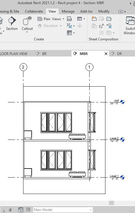
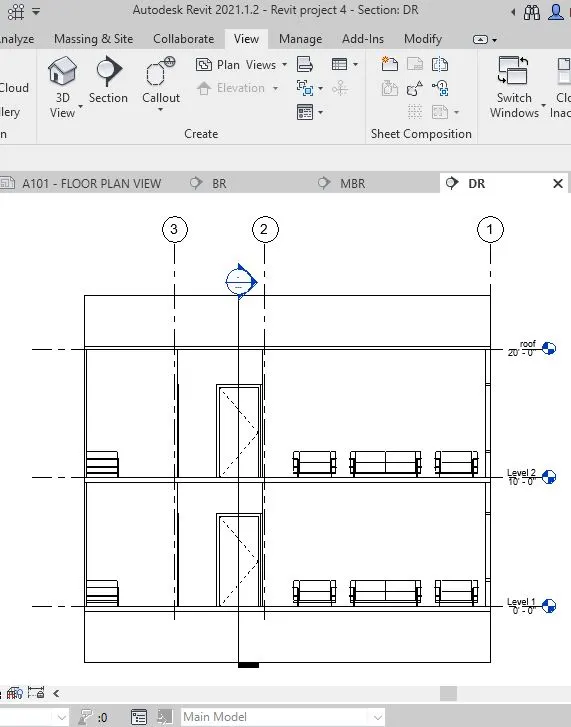
AIM : To create section cut through each room either cutting across longitudinally or in a transverse direction
INTRODUCTION :
Section - A section represent a building model as if the model were cut vertically or horizontally to show interior details. You can create two-dimensional (2D) or three-dimensional (3D) section objects, or a live section view of the model.
PROCEDURE :
- Open Revit from the desktop
- Click on open tab
- Select Revit project 4 file
- Click on View tool
- Click section
- Create section longitudinally and transverse
- Sections of Bedroom, Living room, Dinning room created
RESULT :
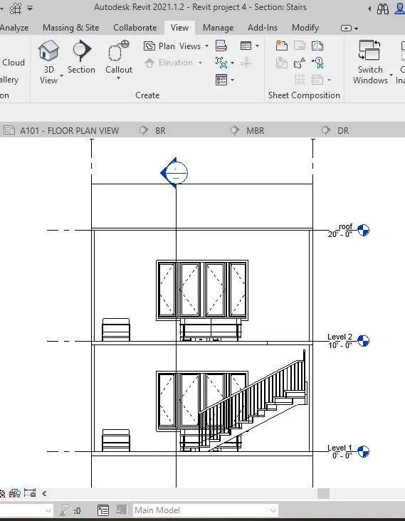
Sections of Bedroom
Sections of Master Bedroom
Sections of Dinning room
Sections of Living room stairs
8) Classify the views, Plan Views, Section Views, and Elevation views to either Design or Documentation category using Properties browser
AIM : To Classify the views, Plan Views, Section Views, and Elevation views to either Design or Documentation category using Properties browser
INTRODUCTION :
Properties browser - The Revit Project Browser is a powerful tool that allows users to navigate and organize their project files and folders. It provides a hierarchical view of your project's elements, views, and sheets, making it easy to locate and manage your design files.
PROCEDURE :
- Open Revit from the desktop
- Click on open tab
- Select Revit project 4 file
- Click on View tool
- Click on views
- Click on plan views
- Click on section views
- Click on elevation views
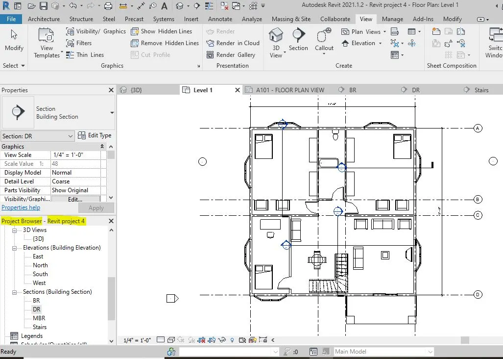
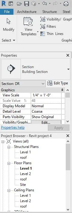
- And we can find all this on Property Browser
RESULT :
Created Design or Documentation category using Properties browser
9) Using the sheet template produced create multiple sheets as follows
a. A 101- Ground Floor Architecture Plan
b. A 102- First Floor Architecture Plan
c. A 103- Roof Plan
d. S 101- Ground Floor Structural Plan
e. S 102- First Floor Structural Plan
f. S 103- Roof Framing Plan
g. A-201- North-South Elevations
h. A-202- East-West Elevations
Add additional sheets based on the sections created in your Revit file
AIM : To use the sheet template produced create multiple sheets
INTRODUCTION :
Sheet template - A sheet view in Revit is a layout where you can place-
- A Titleblock
- Multiple drawings (graphic views such as plan views, sections, elevation, details, 3D views)
- Multiple schedules
- Images
PROCEDURE :
- Open Revit from the desktop
- Click on open tab
- Select Revit project 4 file
- Click on View tool
- Click sheet
- Select Titleblock D 22 X 34 Horizontal
- Click ok
- Change Sheet name
- Change Sheet No. - A101, A102....
- Change sheet issue date
- Change drawn by, checked by, designed by, approved by
- Drag elements into the sheet as per question
RESULT :
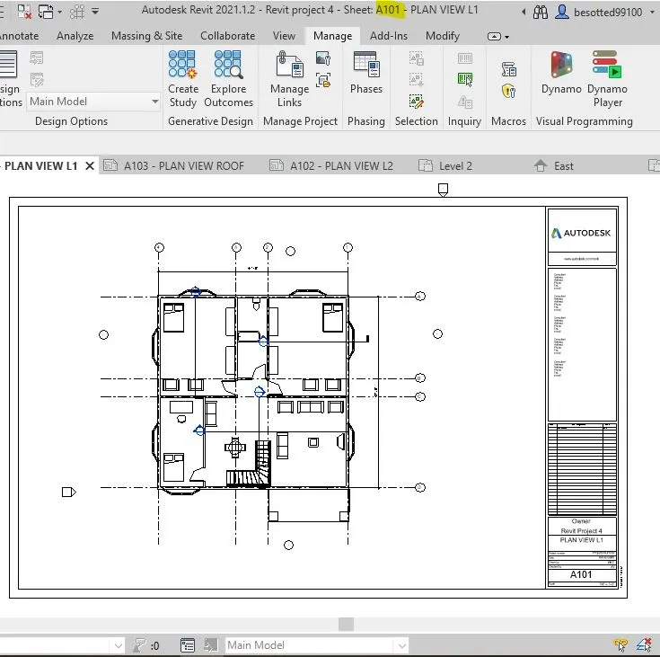
Created Sheet No. - A101
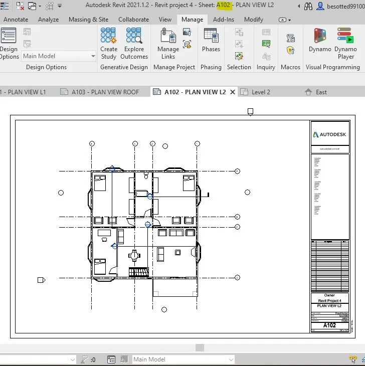
Created Sheet No. - A102
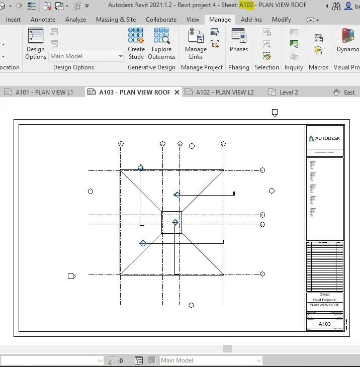
Created Sheet No. - A103
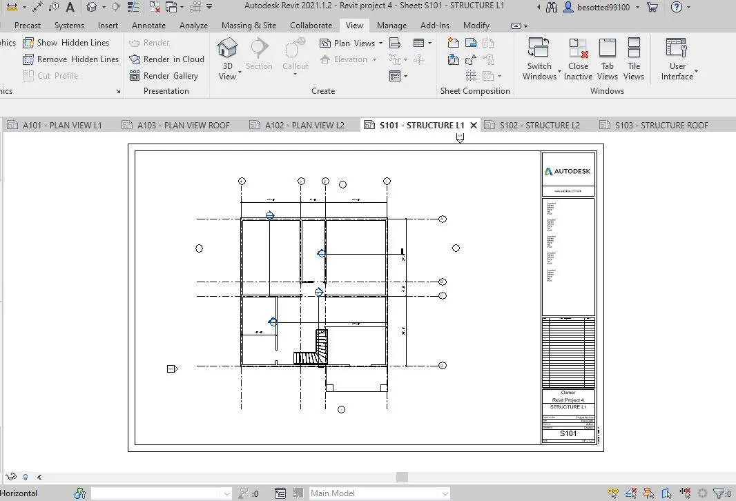
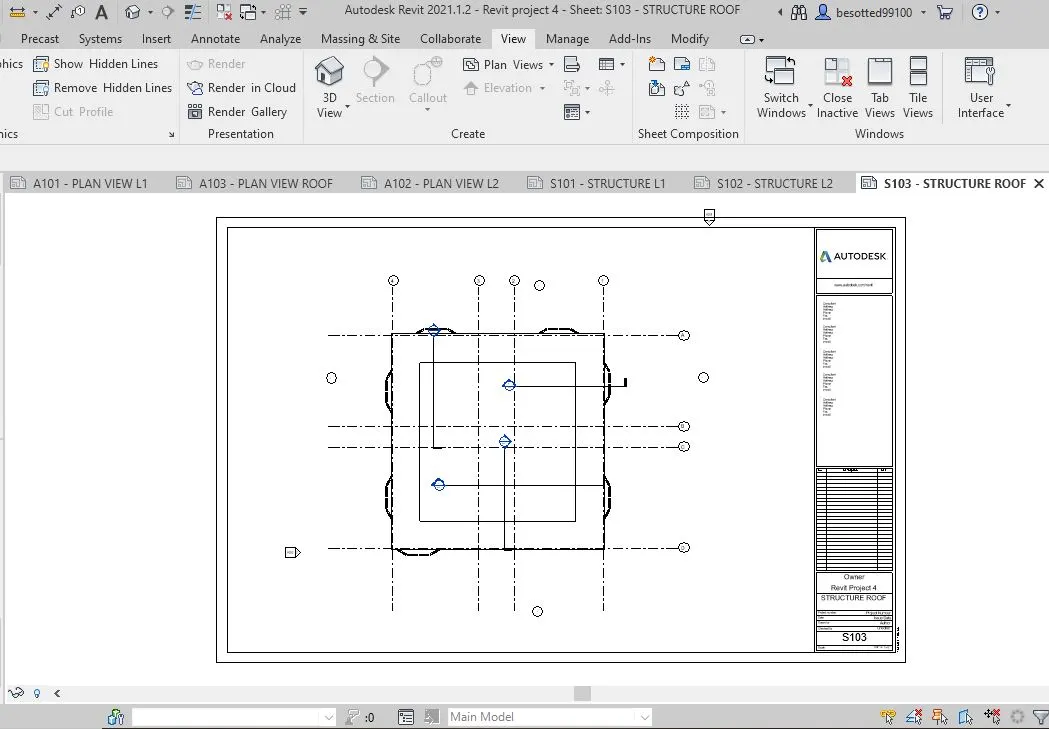
Created Sheet No. - S101
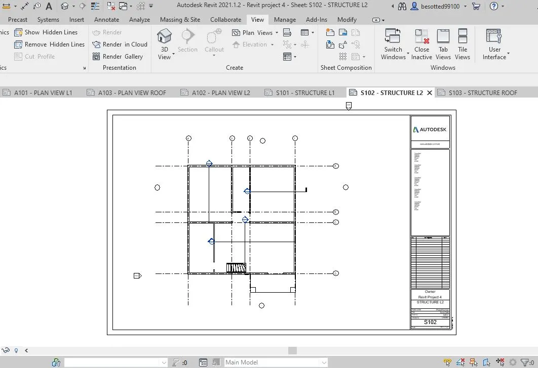
Created Sheet No. - S102
Created Sheet No. - S103
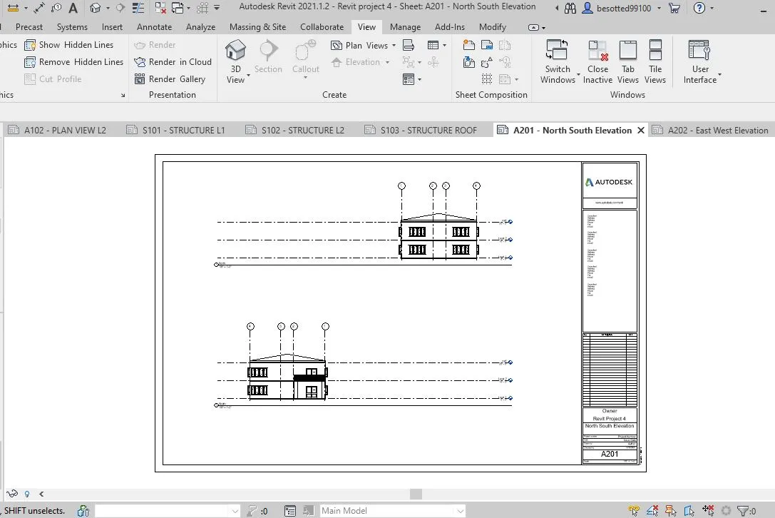
Created Sheet No. - A201
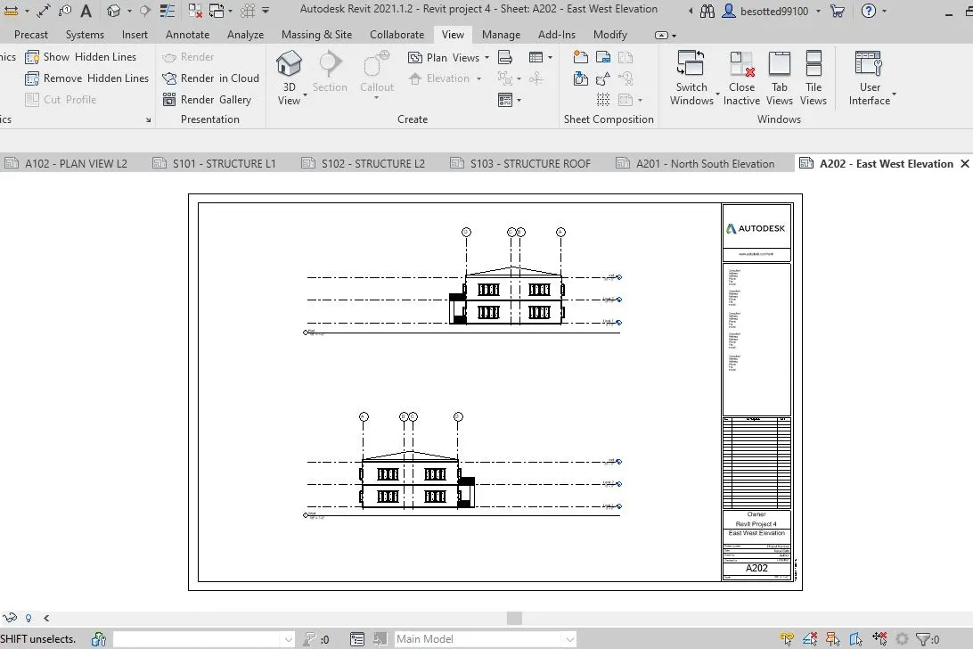
Created Sheet No. - A202
10) Create a camera-specific view or a 3D view in each room ( living, dining, bedroom). Based on the views create a new set of sheets starting A-501 (you can add as many sheets after, 502, 503.. n)to place the 3D view images. Produce the sheets as a part of project drafting.
AIM : To create a camera-specific view or a 3D view in each room ( living, dining, bedroom)
INTRODUCTION :
Camera-specific view - Open the plan view on which the camera position will be set. Set the visibility range to unlimited down and up in the view properties "Range". Find the corresponding 3D view in the project browser. Click "show camera" under the right mouse button.
PROCEDURE :
- Open Revit from the desktop
- Click on open tab
- Select Revit project 4 file
- Click on View tool
- Click 3D view
- Click camera
- Select camera on the plan view
- Now Click on view tool
- Click sheet
- Select Titleblock D 22 X 34 Horizontal
- Click ok
- Change Sheet name
- Change Sheet No. - A501, A502....
- Change sheet issue date
- Change drawn by, checked by, designed by, approved by
- Drag elements into the sheet as per question
RESULT :
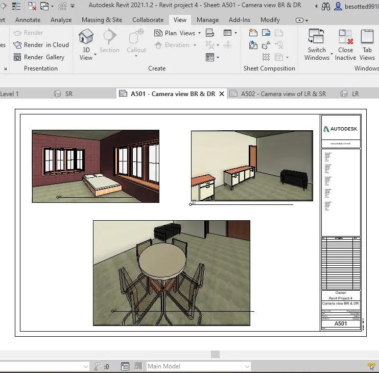
Created Sheet No. - A501
Created Sheet No. - A502