3D Creation of Ceiling, Roof, Architectural plan, Structural plan, Sectional view, Elevation view and Camera specific view for a house plan using REVIT
3D Creation of Ceiling, Roof, Architectural plan, Structural plan, Sectional view, Elevation view and Camera specific view for a house plan using REVIT.
1) Based on the project saved from Week 3, proceed from the First Floor Level. Model a Ceiling from the architecture tab above the walls at the first-floor level.
AIM: To create the ceiling above first floor level by using architectural tab.
Procedure :
1. Click on the ceiling icon in the architectural tab.
2. select the pick line and create the boundary line based on the required shape.
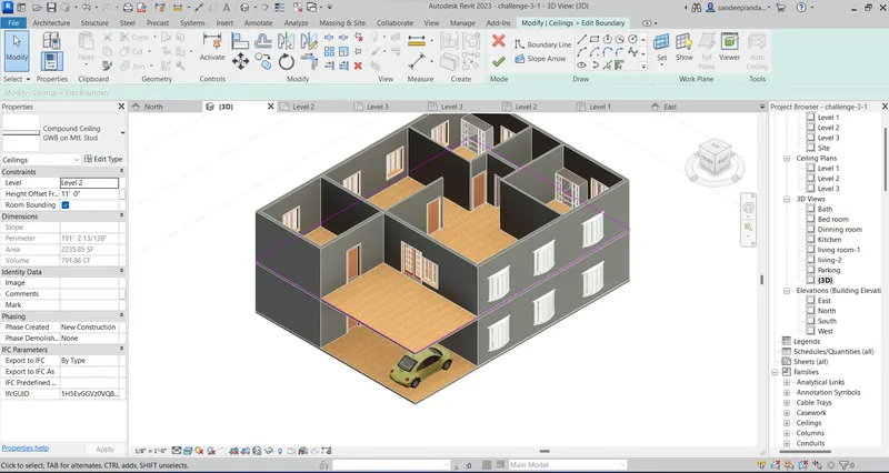
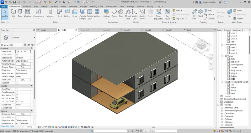
3. Create the required size of the ceiling making duplicate.
4. Fixing the level of the ceiling with proper naming.
Result: Hence the ceiling created.
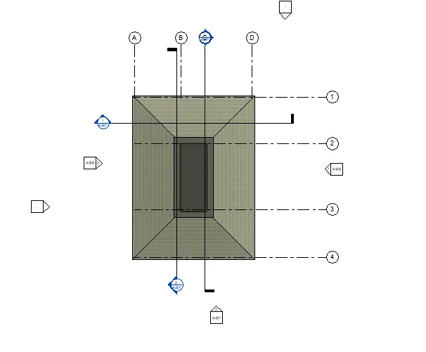
2) Model a roof above the ceiling by selecting the footprints of the ceiling. Using the adjustment toolbars appearing on-screen adjust the roof slope to 10 degrees.
AIM: To create the roof above ceiling by selecting the footprints of the ceiling.
Procedure:
1. Keep the level in ceiling and click on Roof icon in architectural tab.
2. Select on footprint to create the roof with pick line and apply based on the shape.
3. Keep the slope 10 degree by clicking the slope in property tab.
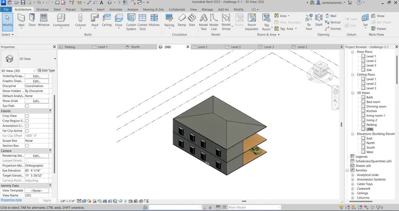
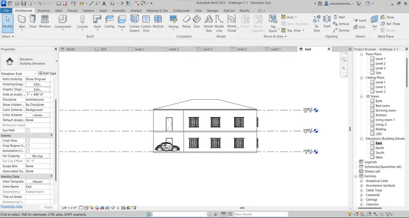
4. Check the roof clicking on elevation tab
Result: Hence the roof created.
3) Using the file saved from weeks 2 to 4, create plan views for ground floor level and first-floor level including all the walls, floors, and components. Separate them to
architecture and structural plans
a. Architecture plan must have walls, floors, and all the components placed within the building
b. Structure plan must have details of only walls, floors, and columns
Architectural plan:
1. Create the plan of ground floor,first floor and roof of building.
2. Click on view tab and select the plan view as architectural plan.
3. It shows walls,doors,windows,floors and components of the building.
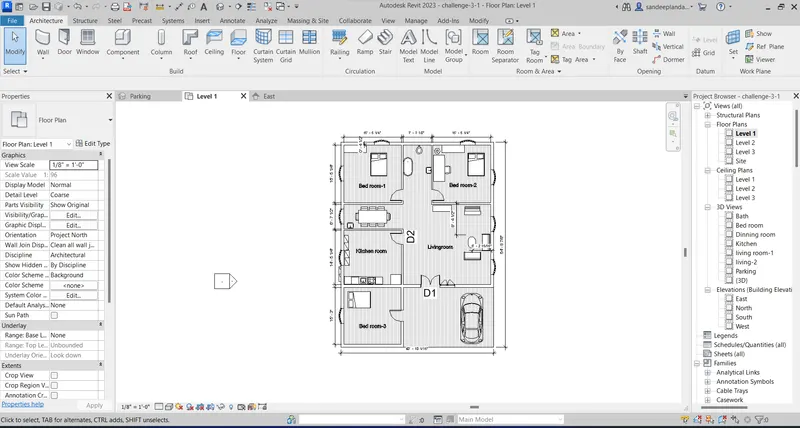
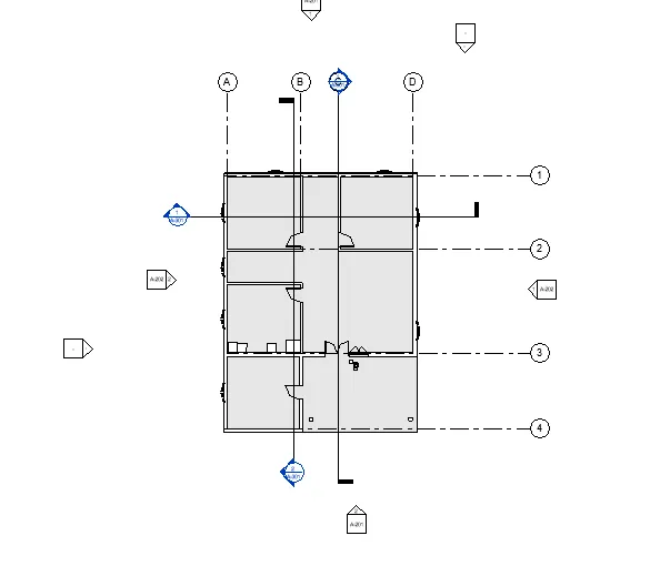
4. First floor of architectural plan.
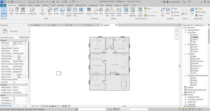
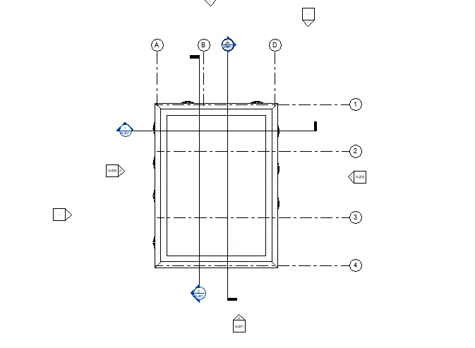
Roof plan
Structural plan
1. Create the structural plan of ground floor,first floor and roof of building.
2. Click on view tab and select the plan view as structural plan.
3. It shows walls,floors of the building.
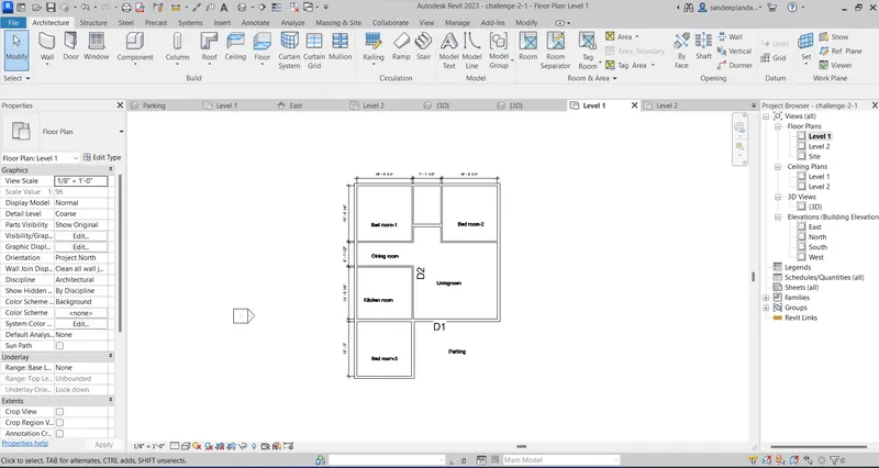
First floor of structural plan.
Roof plan
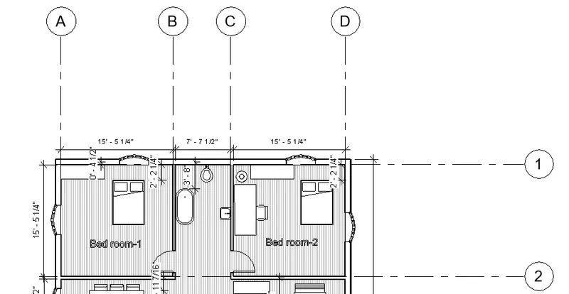
4) Using annotate toolbar add dimensions to all the walls and floors with reference to the longitudinal and transverse grids created in the project file
a. The architecture plan dimensions include details on where the components are placed within the buildings with relation to grids. Overall dimensions are sufficient for architecture plans
b. The Structure plan dimensions must include details on the position of all the walls and interior walls with reference to grids. Locate all the framing components of the building with reference to a fixed point using Structural plans
Procedure :
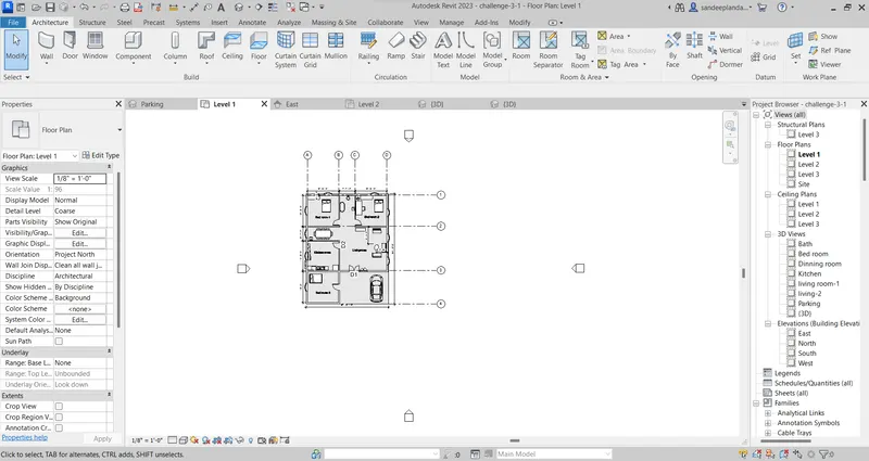
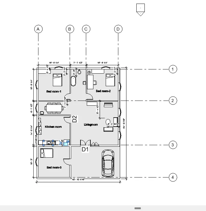
Architectural plan dimension
1. Creating grid line to indicate the dimension based on the grid lines
2. Vertical lines are indicated with numerical and horizontal grid lines indicated with alphabets.
3. Components are dimensioned based on the grid lines.
Structural plan dimension
1. Creating grid line to indicate the dimension based on the grid lines.
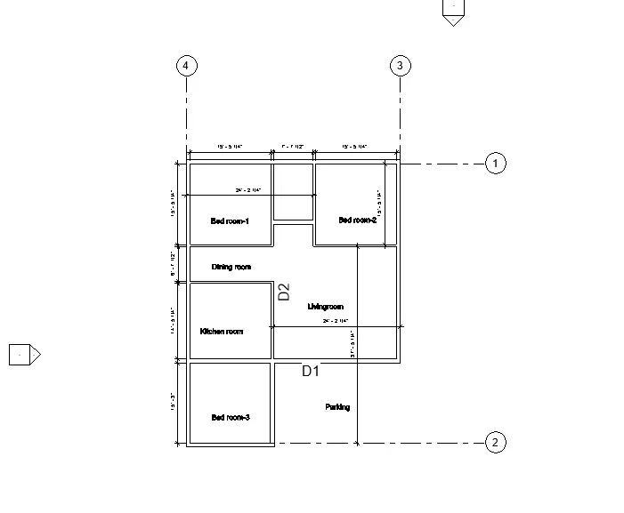
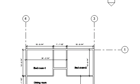
Result: Hence the grid and dimensions are indicated in both architectural and structural.
5) Create a sheet template from the view tab and adjust the parameters on the sheet to add appropriate views.
AIM: To Create a sheet template from the view tab and adjust the parameters on the sheet to add appropriate views.
Procedure:
1. Click on the view tab to select the sheet icon.
2. Click on insert and load the required sheet.
3. Edit the parameters in the property tab and title of the sheets.
4. Change the sheet name,sheet number,creator,checked by,drawn by etc as per the required information of the project.
5. Edit the icon as per the organization and change the address.
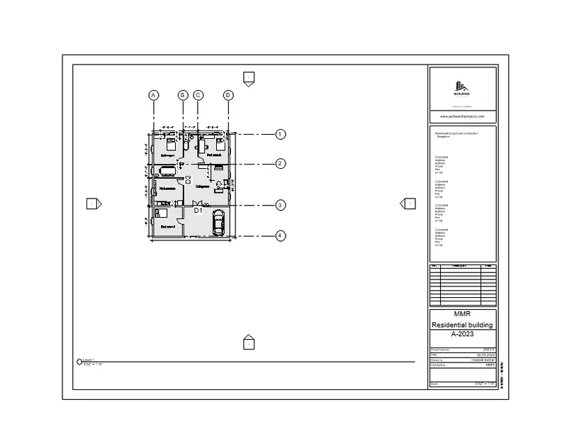
Result: Hence the sheets are created.
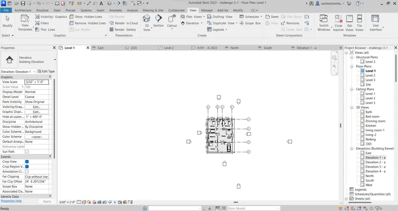
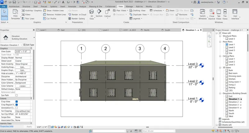
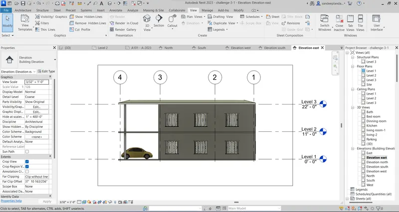
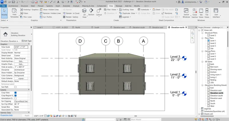
6) Using the elevation tab create the elevation views, looking at your building from East, North, South, and West
AIM: TO create the building elevation view of the direction of east,north,south and west of the residential building.
Procedure :
1. Click view tab and select the elevation tab.
2. Create the camera on the required direction to view the building in 3D.
West elevation:
East elevation:
North elevation:
South elevation:
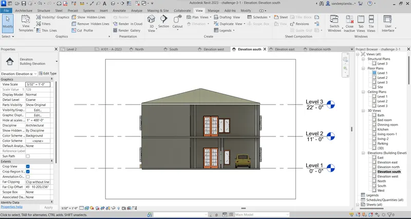
Result: Hence the elevation of the building created.
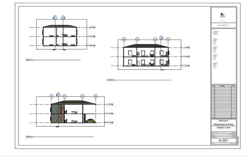
7) Produce section cut through each room either cutting across longitudinally or in a transverse direction.
AIM: Creating section by cut through each room either cutting across longitudinally or in a transverse direction.
Procedure :
1. Click on the view tab and select the section icon to create the section line.
2. Drag the section line one end to other end as per the required.
3. View the section in 3D to take any corrective mesurement.
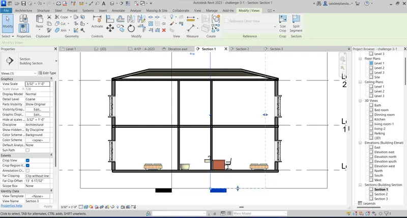
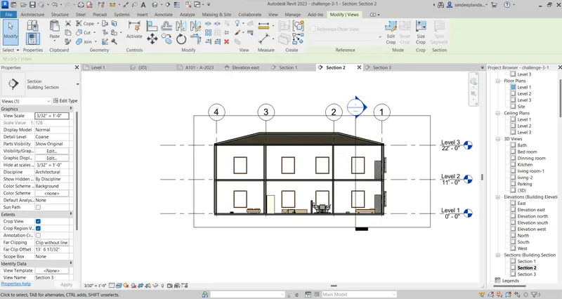
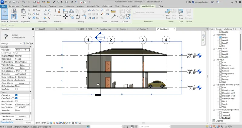
Result: Hence the section of the rooms created.
8) Classify the views, Plan Views, Section Views, and Elevation views to either Design or Documentation category using Properties browser.
AIM: To Classify the views, Plan Views, Section Views, and Elevation views to either Design or Documentation category using Properties browser.
Procedure:
1. project browser shows the overall details of the project.
2. views, Plan Views,Structural view, Section Views,Elevation view and sheet view can be shown in project browser.
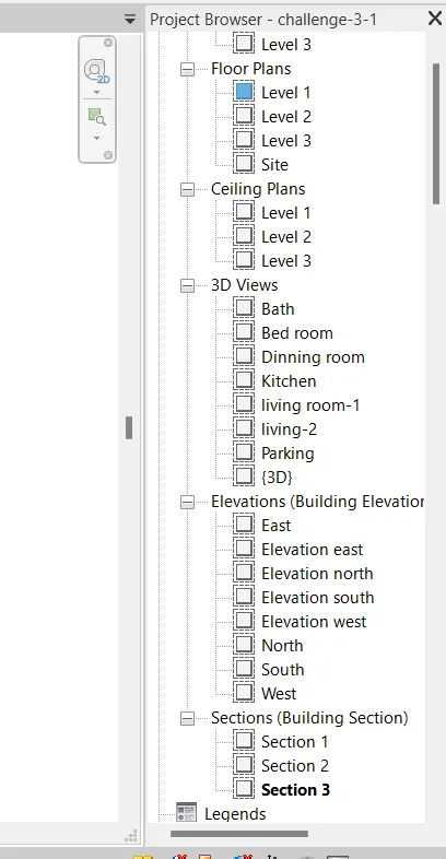
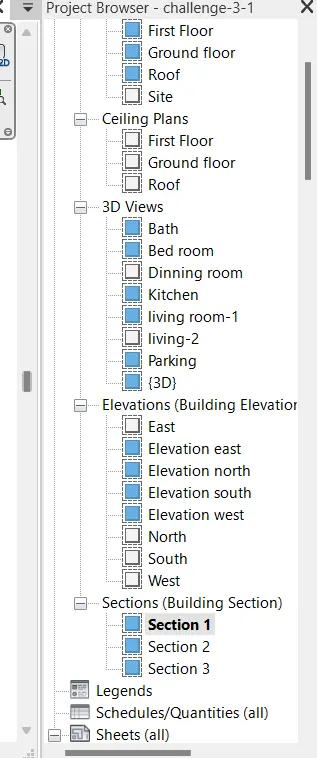
Result: Hence the project browser shown.
9) Using the sheet template produced create multiple sheets as follows
a. A 101- Ground Floor Architecture Plan
b. A 102- First Floor Architecture Plan
c. A 103- Roof Plan
d. S 101- Ground Floor Structural Plan
e. S 102- First Floor Structural Plan
f. S 103- Roof Framing Plan
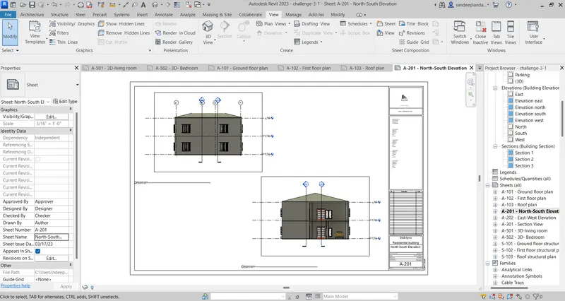
g. A-201- North-South Elevations
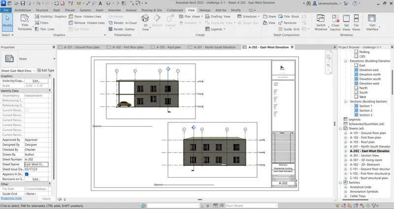
h. A-202- East-West Elevations
1. Creating the sheet template with the plan,structural and elevation.
2. Click on the view tab and open the sheet and select the required sheet.
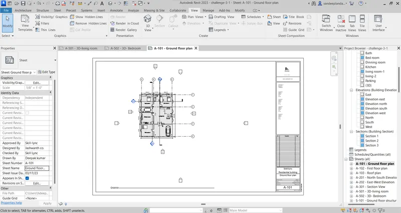
3. Create the architectural plan in the sheet.
A 101- Ground Floor Architecture Plan
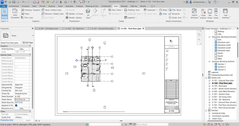
A 102- First Floor Architecture Plan
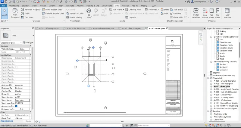
c. A 103- Roof Plan
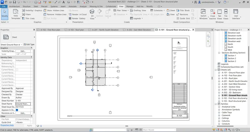
d. S 101- Ground Floor Structural Plan
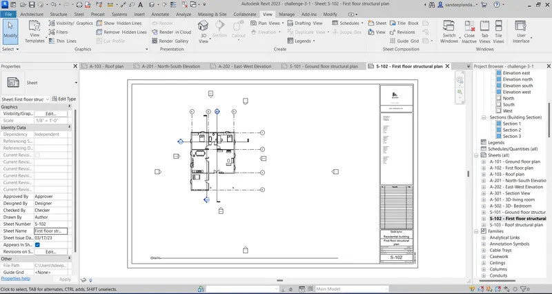
e. S 102- First Floor Structural Plan
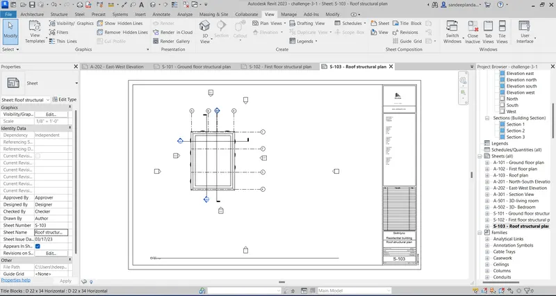
f. S 103- Roof Framing Plan
g. A-201- North-South Elevations
h. A-202- East-West Elevations
l sheets based on the sections
4. Edit the dimension and alignment of the plan and elevation.
Result: Hence the multiple sheets of the plan and elevation created.
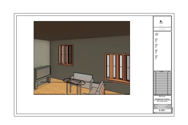
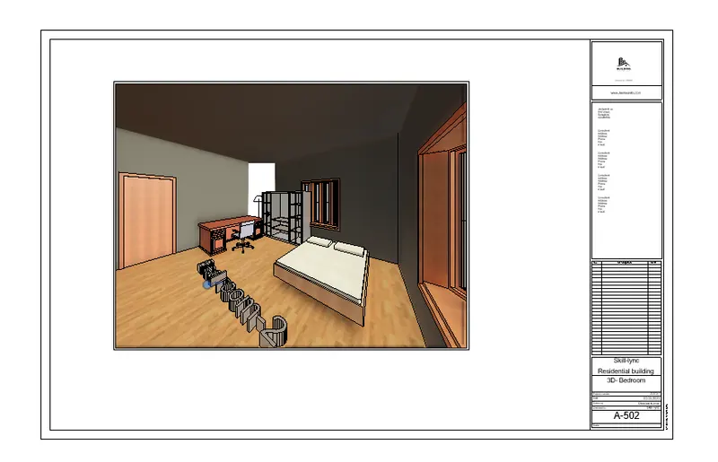
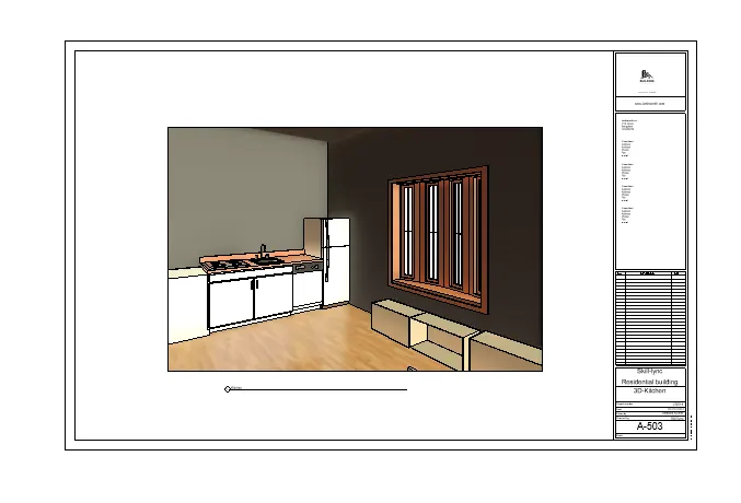
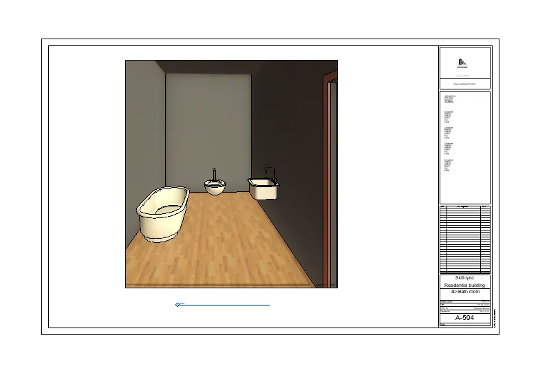
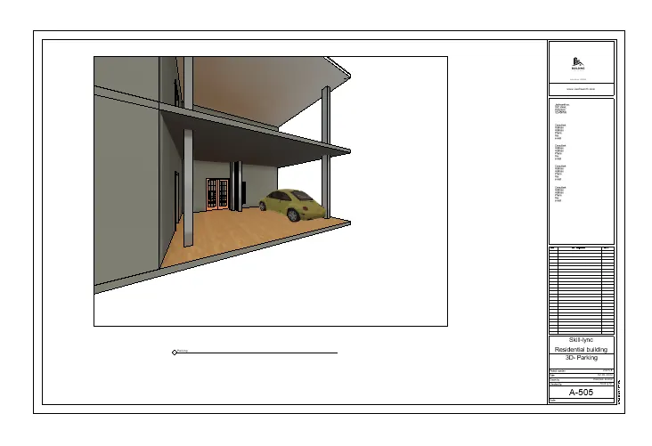
10) Create a camera-specific view or a 3D view in each room ( living, dining, bedroom). Based on the views create a new set of sheets starting A-501 (you can add as many sheets after, 502, 503.. n)to place the 3D view images. Produce the sheets as a part of project drafting.
AIM: TO Create a camera-specific view or a 3D view in each room ( living, dining, bedroom). Based on the views create a new set of sheets starting A-501 (you can add as many sheets after, 502, 503.. n)to place the 3D view images. Produce the sheets as a part of project drafting.
Procedure :
1. Creating the 3D view in the sheets.
2. By clicking the sheet required and selecting the 3D camera view.
3. Edit the draged view with required dimension.
4. Change the sheet name,sheet number,author,created by,checked by and company name,address in the sheet by using property tab.
A-501 living room:
A-502 Bed room:
A-503 Kitchen:
A-504 Bathroom:
A-505 Parking :
A-506 Elevation :
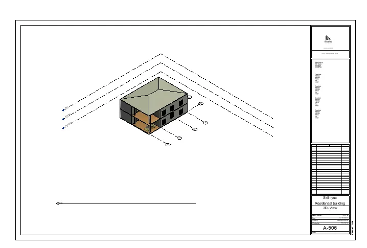
Result: Hence the 3D view created in the sheets.