3D Creation of Ceiling, Roof, Architectural plan, Structural plan, Sectional view, Elevation view and Camera specific view for a house plan using REVIT
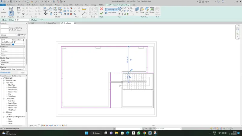
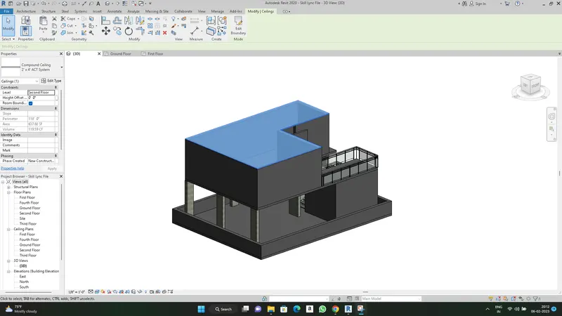
1. Aim: Model a Ceiling from the architecture tab above the walls at the second floor level.
Procedure: A new plan and 3d model has been prepared for the aim of the question. Ceiling option is selected from the architecture tab and then pick line option is taken inorder to sketch the ceiling on the top of the walls. The existing ceiling is chosen in order to ease the process and sketch ceiling is option is considered.
Results: It is observed that the ceiling has been added on the top of the wall.
2. Aim: To Create a roof on the top floor and provide a slope of 10 degrees.
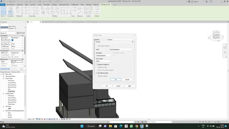
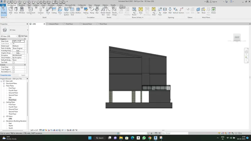
Procedure: The roof is created using roof by footprint where the picck line option has been taken and the border of the ceiling has been utilised to create a roof. The roof is created on the third floor level and a single sided slope of 10 degrees is provided inorder to improve the physical appearance of the building.
No materials have been included so far, it shall be done at the end.
9" inch thick roofs are provided.
Results: A single sided roof is seen as shown in the image below.
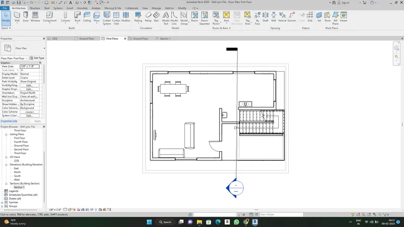
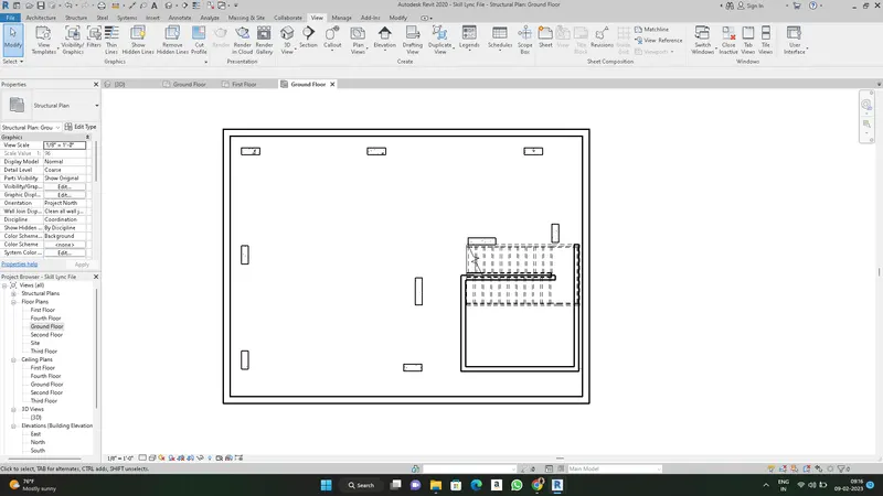
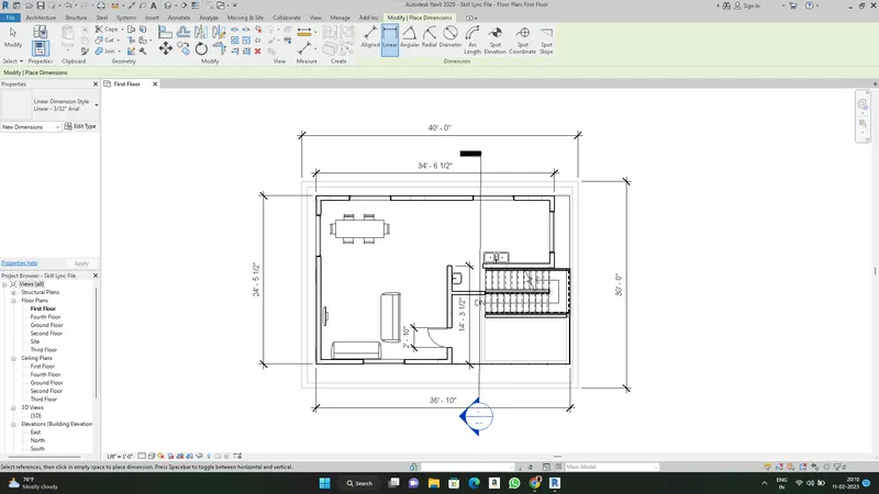
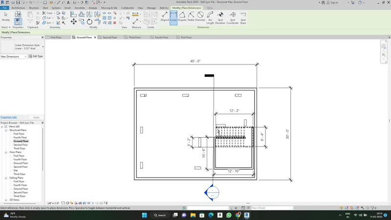
3. The architectural and structural plan of the respective building are attached in the screenshots below.
The structural plan for the building can be obtained by clicking on View > Plan View > Plan view> First Floor ( Level of the plan view required )
The structural plan for the building can be obtained by clicking on View > Plan View > Structural Plan > Ground Floor ( Level of the plan view required )
4.
a. The dimensions for the architectural plan are give below:
this was done by selecting annonate > linear > dimensions of the respective wall.
b. Similiar process was adopted for the dimensions of the structural plan.
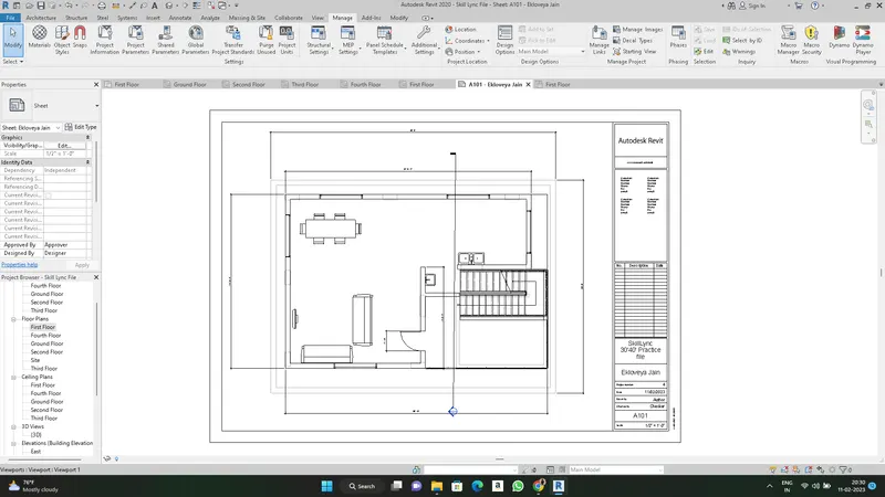
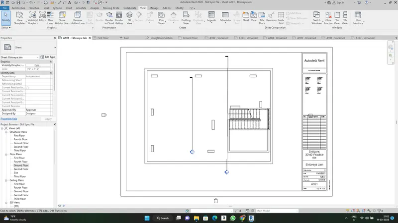
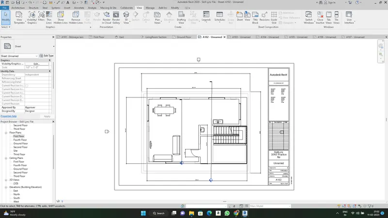
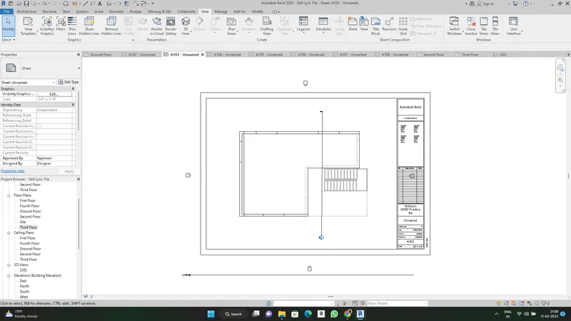
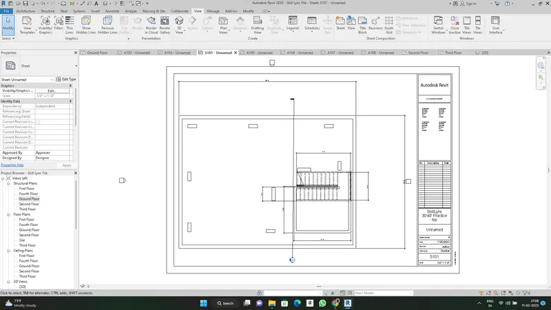
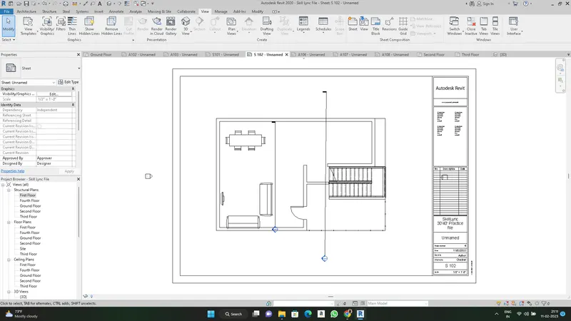
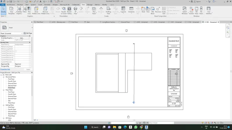
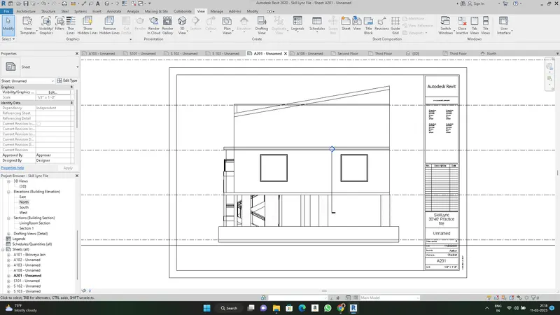
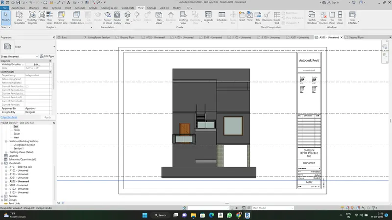
5. The sheets are brought into project using the following method:-
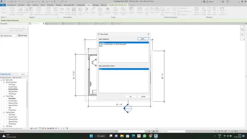
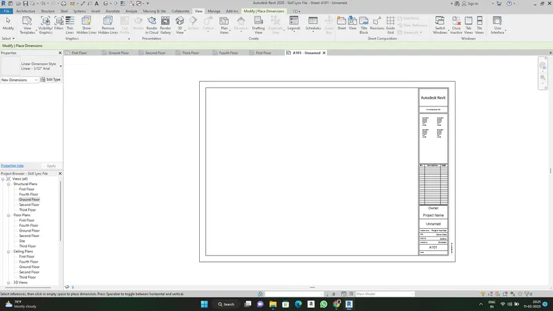
View tab > Sheet > The required sheet is selected and if it is not available then it is loaded from the library > The project information is entered using the manage tab and the required drawing is dragged and dropped to the sheet and a scale is chosen from the properties browser.
This procedure can used for all the types of plans and the sheet numbers can edited accordingly.
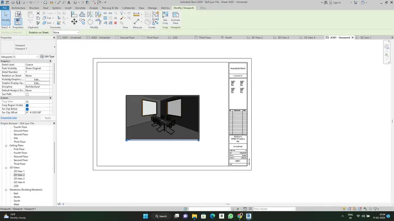
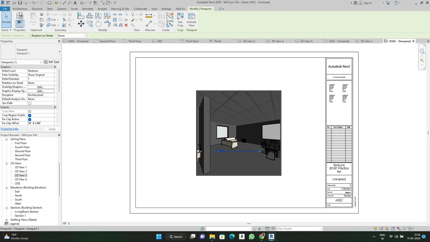
The images of the sheets are provided below and A1 sized sheet was loaded into the project.
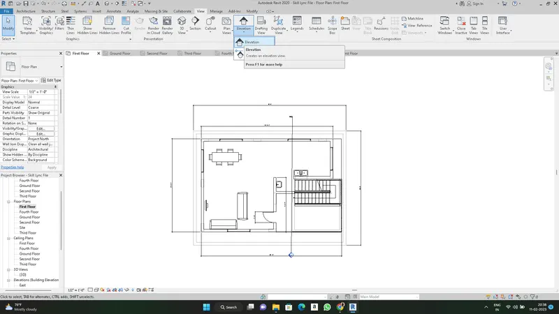
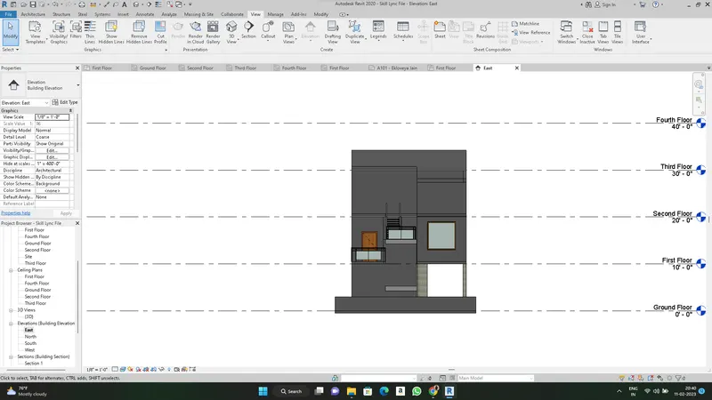
6. The elevation tab is selected from the view tab.
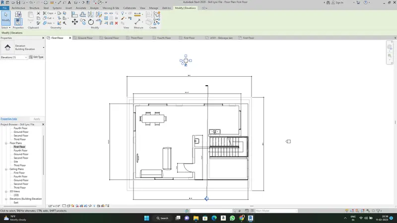
The direction of the elevation is chosen by clicking on the tick mark.
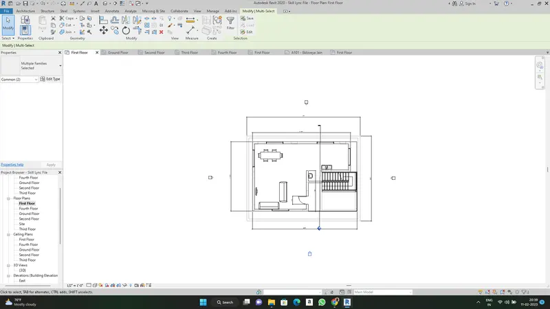
The elevation is renamed.
Similiar procedure is followed for other elevations.
The images of the procedure are given below and the elevation for the east side is provided.
7.
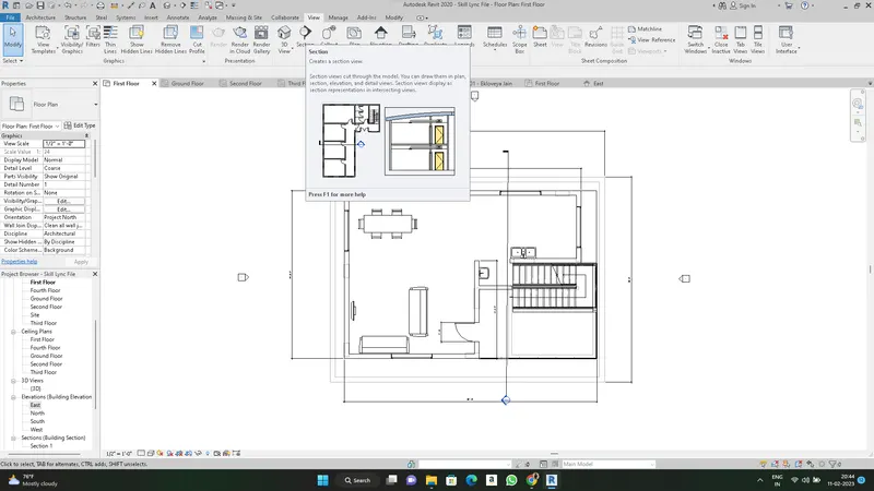
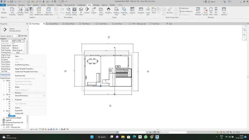
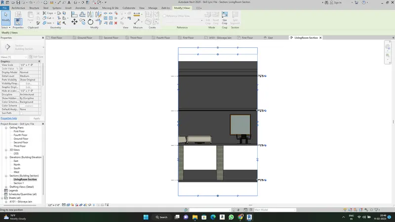
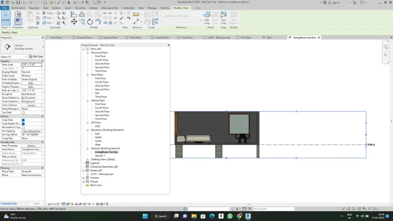
As observed in previous screenshots, the section is already provided for the plan.
View>Section> The section required > Rename if required > Use the points to resize
8.
The views, Plan Views, Section Views, and Elevation views are defined during the project and shown in the image below:
9.
10.