3D Creation of Ceiling, Roof, Architectural plan, Structural plan, Sectional view, Elevation view and Camera specific view for a house plan using REVIT
1) Based on the project saved from Week 3, proceed from the First Floor Level. Model a Ceiling from the architecture tab above the walls at the first-floor level
AIM: To model a ceiling from the architecture tab above the walls at first floor plan
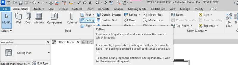
INTRODUCTION: Ceiling is very important for a building for the aesthetic purpose. The creation of ceiling in Revit software is very simple that we can sketch the ceiling as where we want it or automatically ceiling is coming. We can add the ceiling like we did roofing and flooring in the Revit. The ceiling option is seen in the architecture tab. It creates a ceiling at a specified distance above the level in which it resides. For example, if you sketch a ceiling in the floor plan view for level1 the ceiling is created a specified distance above level; 1. To see the ceiling open the Reflected Ceiling Plan view for the corresponding level.
PROCEDURE:
- Open the Revit project saved from week 3
- Select the ceiling option from the architectural toolbar
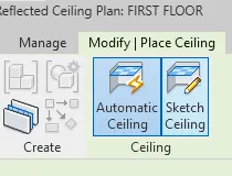
- Select the sketch ceiling option from there
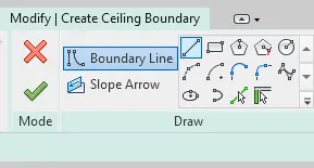
- Select the pick line option
- Ceiling will be created as shown in the figure
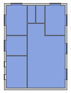
- By selecting the 3D view we can see the 3 dimensional view of the ceiling as shown in the figure
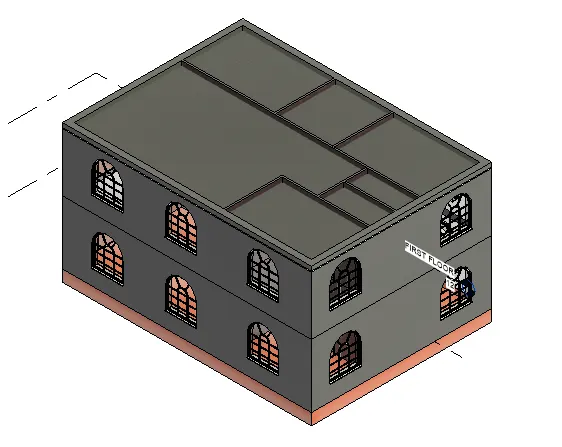
RESULT: The ceiling has been modeled successfully from the architecture tab above the walls at the first-floor level
2) Model a roof above the ceiling by selecting the footprints of the ceiling. Using the adjustment toolbars appearing on-screen adjust the roof slope to 10 degrees
AIM: To model a roof above the ceiling by selecting the footprints of the ceiling.
INTRODUCTION: Roof is the top covering of the building that protect the building from all weather conditions. Roofs can be constructed in a wide variety of forms flat, pitched, vaulted, domed or in combinations as dictated by technical, economical, or aesthetic considerations.
There are several type of roof creation option in Revit. Roof by footprint creates a roof using the building footprint to define its boundaries. To create the roof by footprint, opem a floor plan view or reflected ceiling plan view. You can specify different slopes and overhangs fro the roof when you create it or use default values and define them later.
PROCEDURE:
- Open the architectural toolbar and select the roof by footprint option as shown
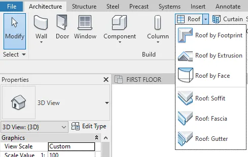
- Pick the lines and create the roof
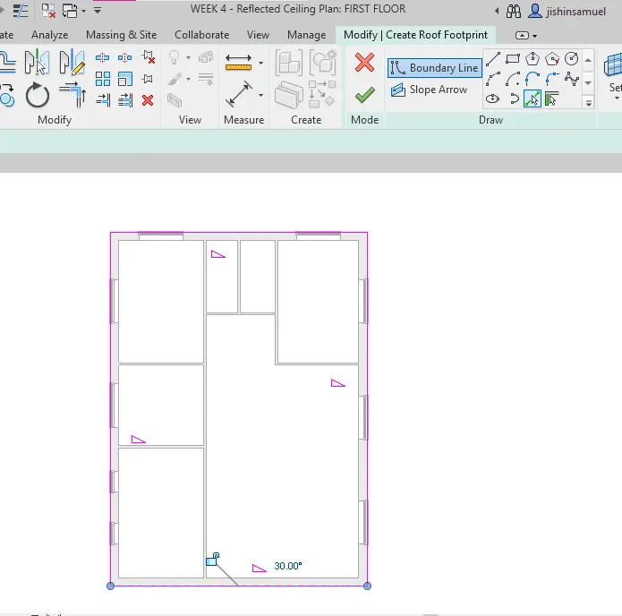
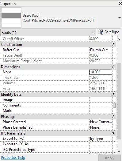
- From the property browser chage the slope of the roof as 10 degree
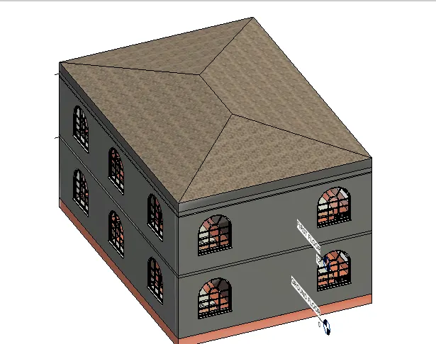
- The roof has been created
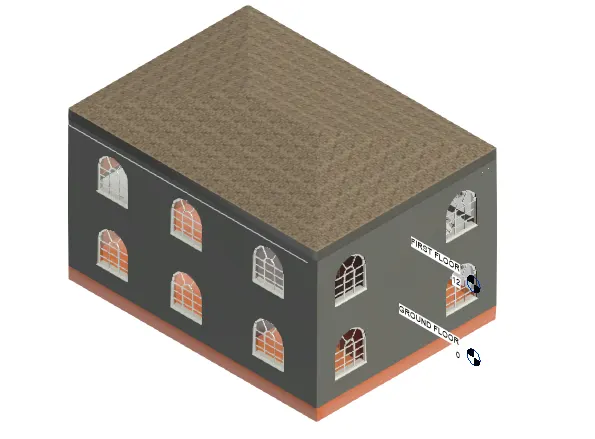
RESULT: The roof has been created successfully to the model in the revit in the detailed manner
3) Using the file saved from weeks 2 to 4, create plan views for ground floor level and first-floor level including all the walls, floors, and components. Separate them to architecture and structural plans
a. Architecture plan must have walls, floors, and all the components placed within the building
b. Structure plan must have details of only walls, floors, and columns
AIM: To create plan views for the ground floor level and first floor level including all the walls, floors and components and separate them to architectural and structural plans.
INTRODUCTION:
- The structural plan view is the default view when you start a project using a structural template. Most projects include atleast one structural plamn. New structural view are created automatically when we add new level. Most projects are atleast one floor plan. New architectural floors are created as add new levels.
PROCEDURE:
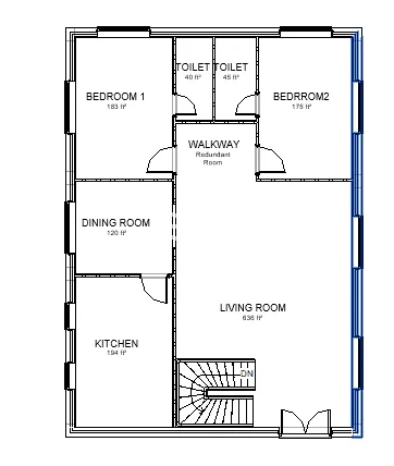
- Draw the architectural plan of ground floor and first floor
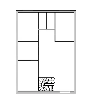
- Separate the architectural and structural plans
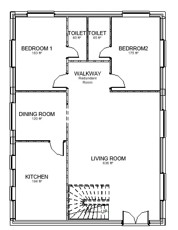
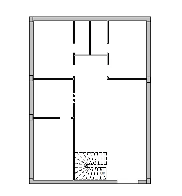
RESULT:
- Created plan views for ground floor level and first floor level including the walls floor and other components
- Separated them into architectural and structural plans
4) Using annotate toolbar add dimensions to all the walls and floors with reference to the longitudinal and transverse grids created in the project file
a. The architecture plan dimensions include details on where the components are placed within the buildings with relation to grids. Overall dimensions are sufficient for architecture plans
b. The Structure plan dimensions must include details on the position of all the walls and interior walls with reference to grids. Locate all the framing components of the building with reference to a fixed point using Structural plans
AIM: To add dimensions to all the walls and floors with reference to the longitudinal and transverse grids created in the project file.
INTRODUCTION:
- Dimensioning is very important in a particular plan. The dimensionsioning are done with respect to the gridlines for the easy way of execution it in the site. Grid lines are the basic component of a plan so that we can transfer the plan through the grid lines. The architectural plan and structural plans are needed for the designing.
PROCEDURE:
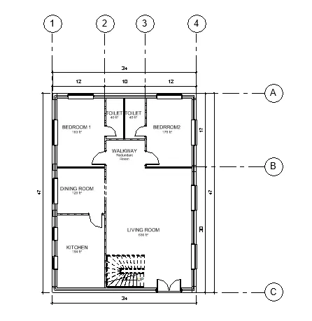
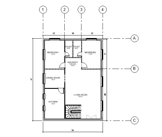
- Draw the longitudinal and transverse grids to the architectural floor plans as shown
- Add the dimensions to the architectural plan
- Add the dimensions in the linear dimension in annotate tab
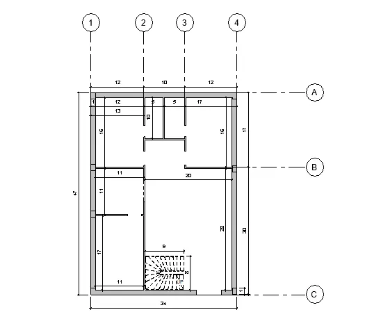
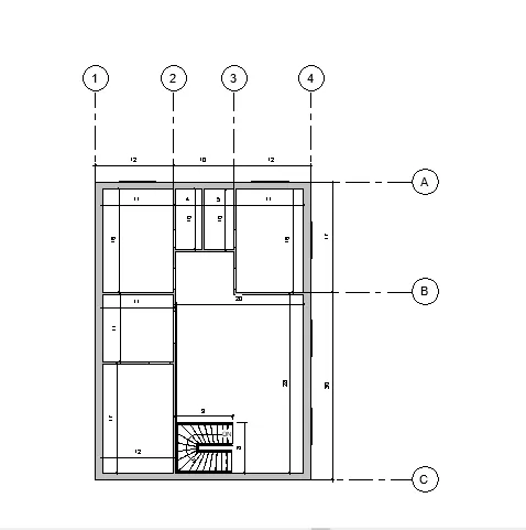
RESULT:
- The dimensions are added to the structural floor plans and the architectural floor plan.
- The longitudinal and transverse grids are created in the project file
5) Create a sheet template from the view tab and adjust the parameters on the sheet to add appropriate views
AIM: To create sheet template from the view tab and adjust the parameters on thesheets to add appropriate views
INTRODUCTION:
- Create views on a project template before you start building the model to streamline the project documentation proess
- When creating a project template can include sheets in the template. Start with a blank project file and create the standard views and levels that each project should include
- Leave the views empty, but assign standard names to them. To create the standard set of construction documents create sheets using desired title blocks
PROCEDURE:
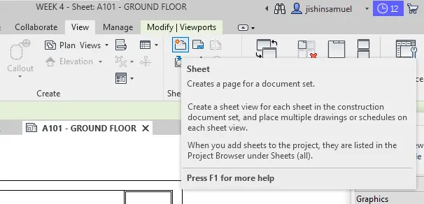
- Click on the sheet option from the view toolbar
- the new tab will be visible on the screen
- Sheet template will be displayed
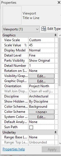
- Insert the ground floor plans and first floor plans separately
- Edit the project name and the sheet number
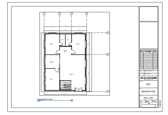
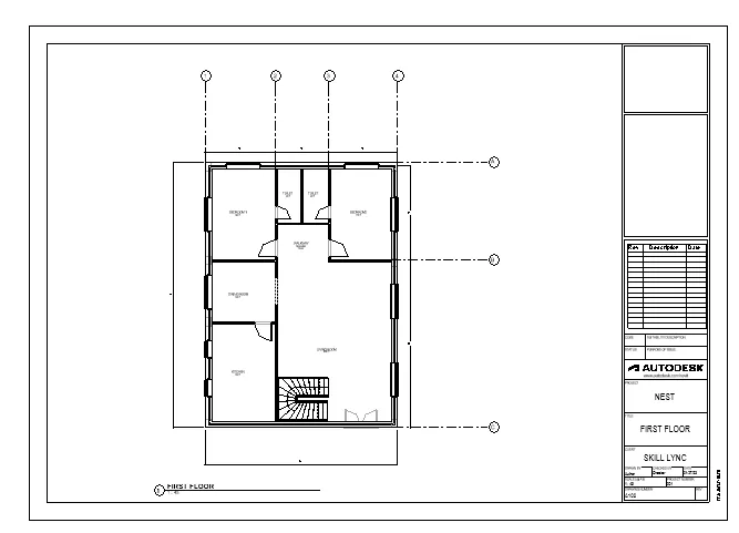
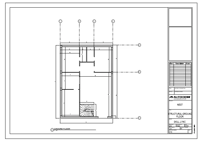
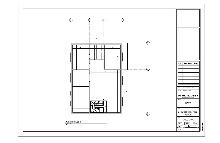
RESULT: Created the sheet template from the view tab and adjusted the parameters on the sheet for adding appropriate views
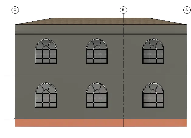
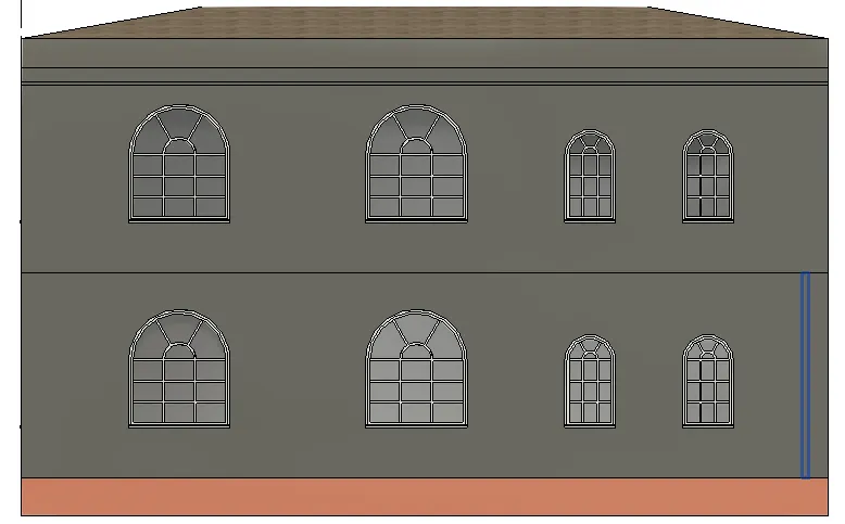
6) Using the elevation tab create the elevation views, looking at your building from East, North, South, and West
AIM: To create the elevation views using elevation tab looking at the building from East, West, North, South
INTRODUCTION: An elevation is a view of a building seen from one side. It is used to describe the external appearance of a building. Each elevation is labelled in relation to the compass direction it faces
PROCEDURE:
- Click the elevation option from the view toolbar
- Insert the compass to north, south, east, west
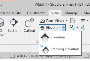
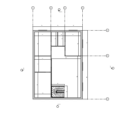
- From the project browserthe elevation from the north, south, east, west as shown below
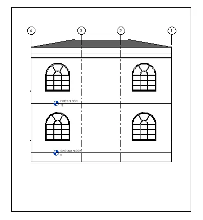
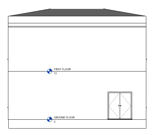
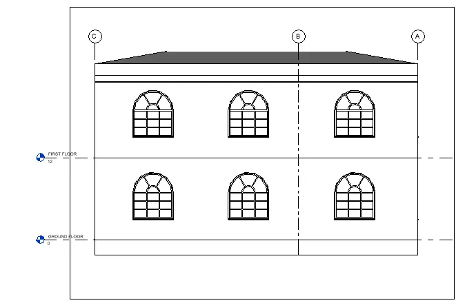
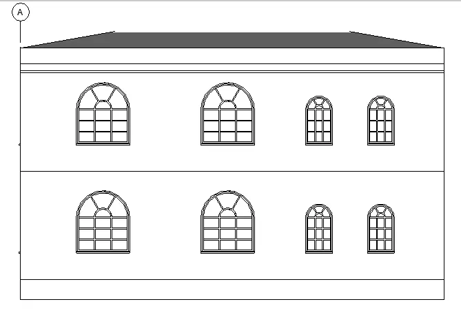
RESULT: Created the elevation views, looking at the building from East, South, North, West using the elevation tab
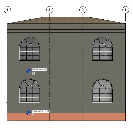
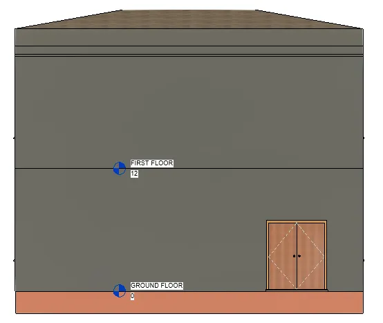
7) Produce section cut through each room either cutting across longitudinally or in a transverse direction
AIM: To produce the section cut through each room either cut across longitudinally or in transverse direction
INTRODUCTION:
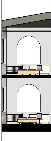
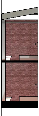
Sectional views reveal hidden details in the drawing. These views assume that a cutting plane has removed portions of the object represented by the drawing, displaying the appropriate section of the interior. The sectional views are used in engineering drawings and architectural drawings.
PROCEDURE:
- Click on the section option rom the view toolbar
- Produce the section view of the bedroom
- Produce the section view of bathroom
- Produce the section view of the bedroom
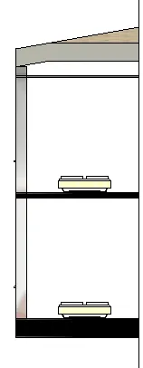
- Produce the section view of the dining room
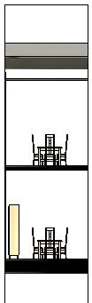
- Produce the section view of the kitchen
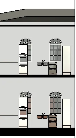
- Produce the section view of the living room
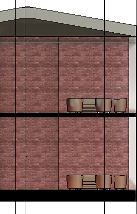
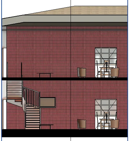
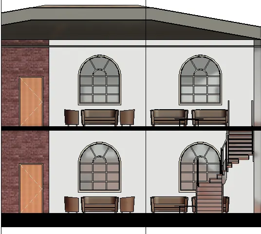
RESULT: Created the section views of a model in the revit in detailed manner
8) Classify the views, Plan Views, Section Views, and Elevation views to either Design or Documentation category using Properties browser
AIM: To classify the views to either design or documentation category using property browser
INTRODUCTION: Create views on a project template before you start building the model to streamline the project documentation proess.When creating a project template can include sheets in the template. Start with a blank project file and create the standard views and levels that each project should include. Leave the views empty, but assign standard names to them. To create the standard set of construction documents create sheets using desired title blocks
An elevation is a view of a building seen from one side. It is used to describe the external appearance of a building. Each elevation is labelled in relation to the compass direction it facesSectional views reveal hidden details in the drawing. These views assume that a cutting plane has removed portions of the object represented by the drawing, displaying the appropriate section of the interior. The sectional views are used in engineering drawings and architectural drawings.
PROCEDURE:
- Open the project browser, the views, plan view, section view, elevation view are visible in the project browser
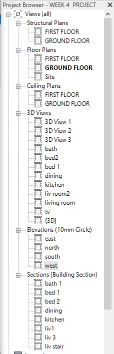
RESULT: Classified the views, lan view, section view, and elevation view to either design or documentation category using project browser
9) Using the sheet template produced create multiple sheets as follows
a. A 101- Ground Floor Architecture Plan
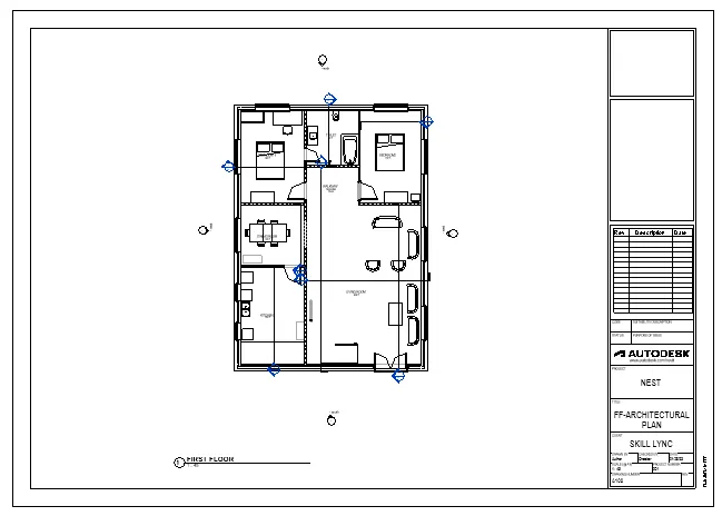
b. A 102- First Floor Architecture Plan
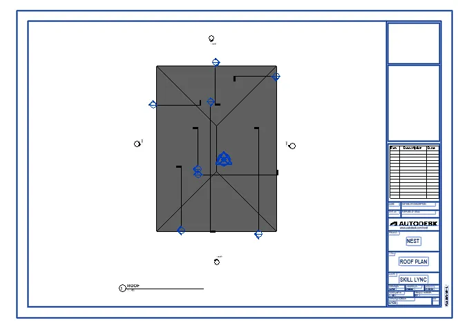
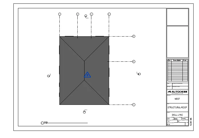
c. A 103- Roof Plan
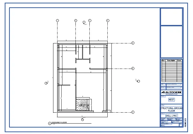
d. S 101- Ground Floor Structural Plan
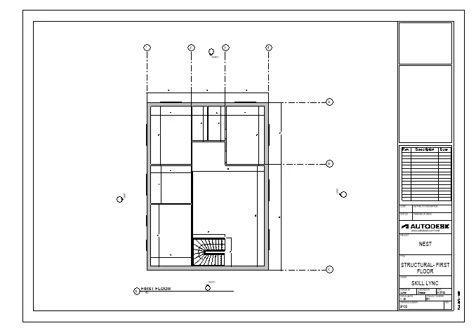
e. S 102- First Floor Structural Plan
f. S 103- Roof Framing Plan
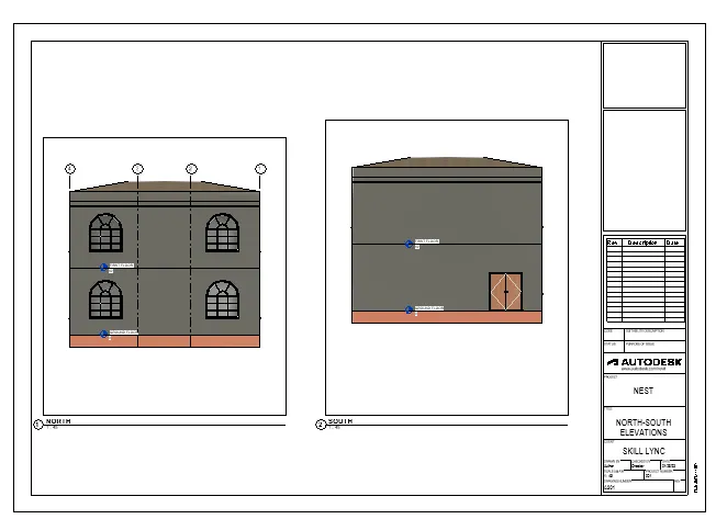
g. A-201- North-South Elevations
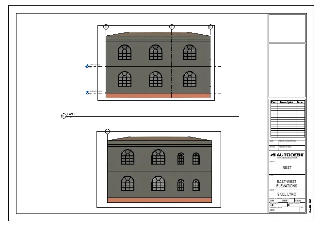
h. A-202- East-West Elevations
AIM: To create the multiple sheets and produce the drawings in the sheets from the given list
INTRODUCTION: Create views on a project template before you start building the model to streamline the project documentation proess.When creating a project template can include sheets in the template. Start with a blank project file and create the standard views and levels that each project should include. Leave the views empty, but assign standard names to them. To create the standard set of construction documents create sheets using desired title blocks
An elevation is a view of a building seen from one side. It is used to describe the external appearance of a building. Each elevation is labelled in relation to the compass direction it facesSectional views reveal hidden details in the drawing. These views assume that a cutting plane has removed portions of the object represented by the drawing, displaying the appropriate section of the interior. The sectional views are used in engineering drawings and architectural drawings.
PROCEDURE:
- Produce the ground floor architectural plan in the sheet template A-101 as shown in the figure
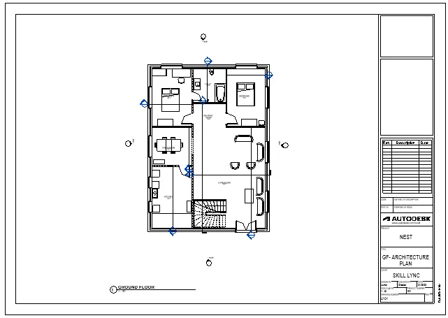
- Produce the first floor architectural plan in the sheet template A-102 as shown in the figure
- Produce the roof plan in the sheet template A-103 as shown in the figure
- Produce the ground floorstructural plan in the sheet template S-101 as shown in the figure
- Produce the first floorstructural plan in the sheet template S-102 as shown in the figure
- Produce the roof floorframe plan in the sheet template S-103as shown in the figure
- Produce North- South elevation views in the sheet template A-201
- Produce East- West elevation views in the sheet template A-201
- Produce section views in the sheet template
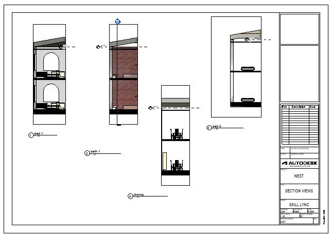
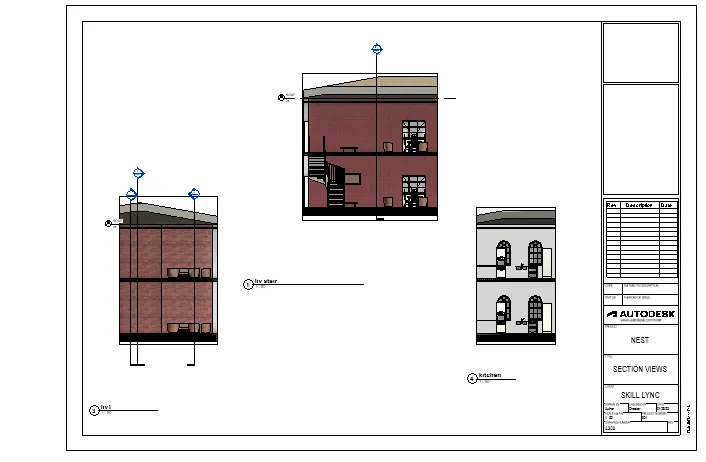
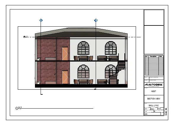
RESULT: Created multiple sheets and produced the drawing in the sheets
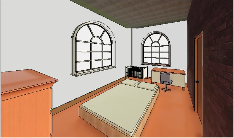
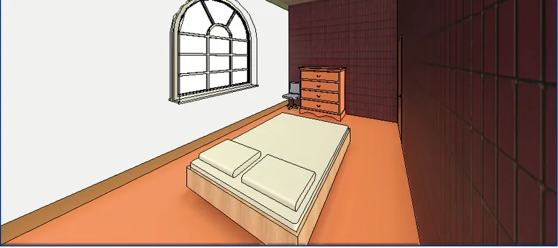
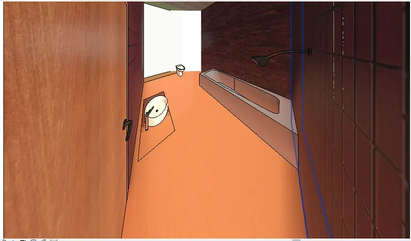
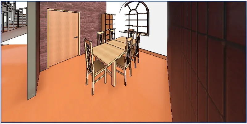
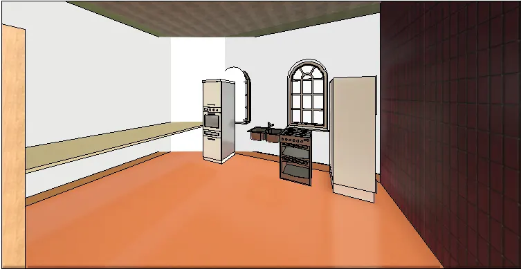
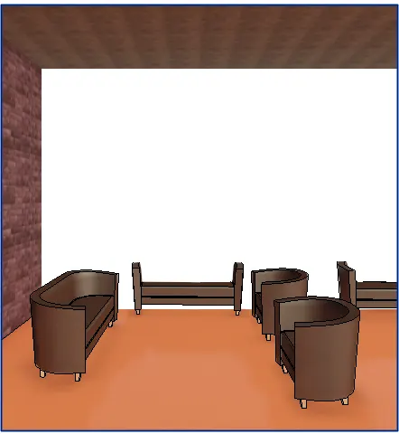
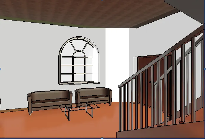
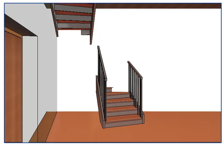
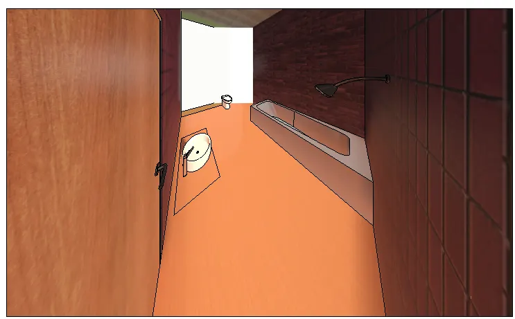
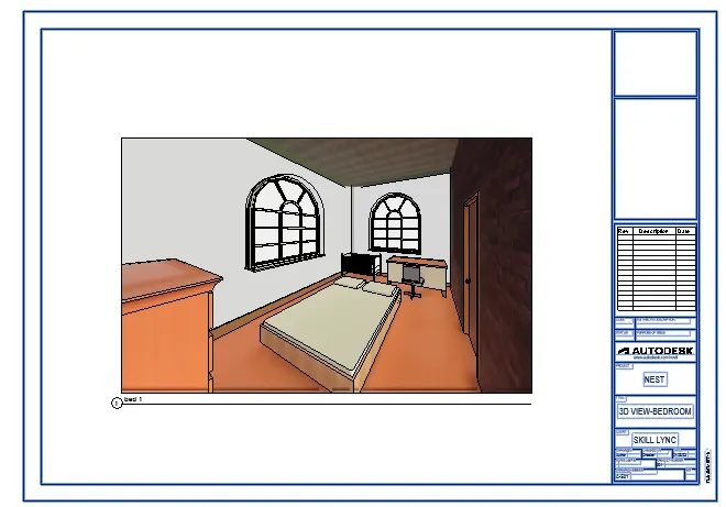
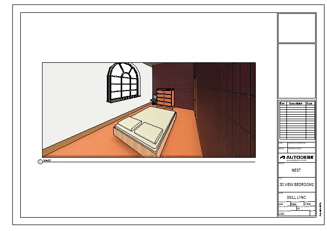
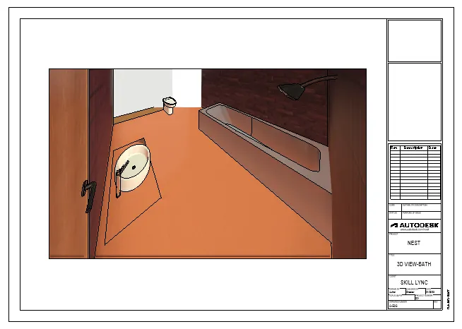
10) Create a camera-specific view or a 3D view in each room ( living, dining, bedroom). Based on the views create a new set of sheets starting A-501 (you can add as many sheets after, 502, 503.. n)to place the 3D view images. Produce the sheets as a part of project drafting.
AIM: To create camera specific view or a 3D view in the living room, dining room and bedroom in the sheets respectively
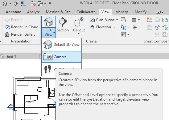
INTRODUCTION: The camera views are really useful in Revit. This allows us to view what we actually see if we were standing at a particular location. It represents the real view of the building.
PROCEDURE:
- Select the camera in the 3D View option in the view tab
- Create the 3D views of bedroom, living room, bathroom, kitchen, dining room
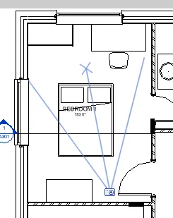
- Take the sheet and name it as A-501
- Next go thebedroom viewand drag the views in the sheet
- Take the sheet and name it as A-502
- Next go thebedroom viewand drag the views in the sheet
- Take the sheet and name it as A-503
- Next go the bath viewand drag the views in the sheet
- Take the sheet and name it as A-504
- Next go the dining hall viewand drag the views in the sheet
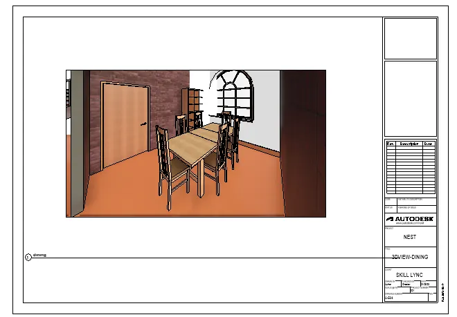
- Take the sheet and name it as A-505
- Next go the kitchen viewand drag the views in the sheet
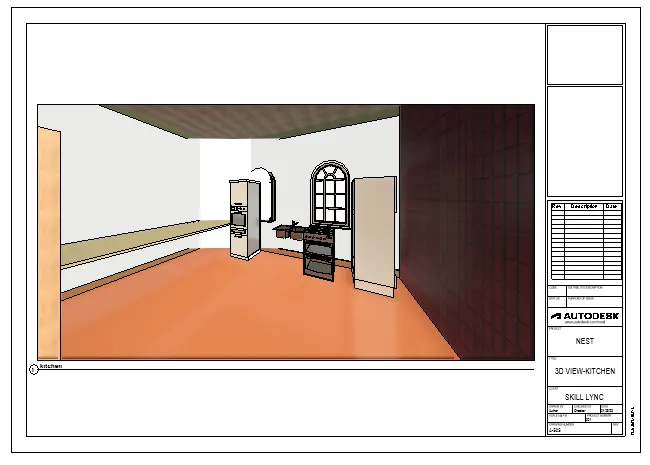
- Take the sheet and name it as A-506
- Next go the living room viewand drag the views in the sheet
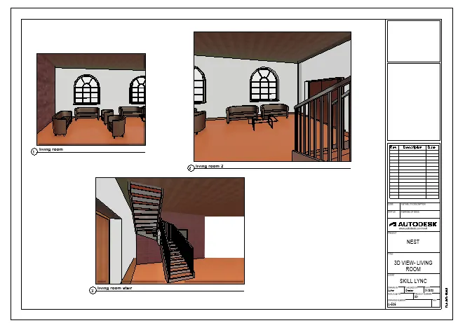
RESULT: Created the camera -specific view or a 3D view in the living room dining room, and bedroom in the sheets separately